

Ä |
|
HEATING AND AIR CONDITIONING 24 - 31 |
|
Fig. 9 High Pressure Relief Valve Removal
COMPRESSOR MAIN OR SUB CONTROL VALVES
If the main or sub control valve is leaking refrigerant to the atmosphere, replace the main or sub control valve. If a functional problem is suspected with the main or sub control valve, the compressor should be replaced.
REMOVAL AND INSTALLATION
(1)Discharge the refrigerant system.
(2)Remove the compressor assembly. Position it to gain access to the control valves. It is not necessary to disconnect the suction or discharge lines from the compressor.
(3)Remove the snap ring retaining either the main or sub control valve to the compressor (Fig. 10).
Fig. 10 Main or Sub Control Valve Snap Ring
(4) Pull the main or sub control valve from the compressor end cover (Fig. 11).
Fig. 11 Remove or Install Main or Sub Control Valve
To install, reverse the preceding operation using new O-ring seals. Evacuate and charge the refrigerant system.

24 - 32 HEATING AND AIR CONDITIONING |
|
|
|
Ä |
|
|
|
|
|||
FIXED DISPLACEMENT COMPRESSOR SERVICE PROCEDURESÐMODEL 10PA17 |
|||||
|
|
INDEX |
|
|
|
|
|
page |
|
page |
|
Compressor Clutch/Coil AssemblyÐ |
|
|
Compressor High-Pressure Relief Valve . . . . . . . |
. 36 |
|
Model 10PA17 . . . . . . . . . . . . . . . . . . . . . |
. . 32. . |
Compressor Removal and Installation . . . . . . . . . |
. 32 |
||
Compressor Front Shaft SealÐModel 10PA17 |
. . . 34 |
|
|
|
|
COMPRESSOR REMOVAL AND INSTALLATION
The A/C compressor may be removed and positioned without discharging the refrigerant system. Discharging is not necessary if removing the A/C compressor clutch/coil assembly, engine, cylinder head, or alternator.
WARNING: REFRIGERANT PRESSURES REMAIN HIGH EVEN THOUGH THE ENGINE MAY BE TURNED OFF. BEFORE REMOVING A FULLY CHARGED COMPRESSOR, REVIEW THE SAFETY PRECAUTIONS AND WARNINGS SECTION IN THIS GROUP. DO NOT TWIST OR KINK THE REFRIGERANT LINES WHEN REMOVING A FULLY CHARGED COMPRESSOR. SAFETY GLASSES MUST BE WORN.
(1)Disconnect Negative battery cable.
(2)Loosen and remove drive belts (refer to Group 7, Cooling System) and disconnect compressor clutch wire lead.
(3)Remove refrigerant lines from compressor (if necessary).
(4)Remove compressor attaching nuts and bolts.
(5)Remove compressor. If refrigerant lines were not removed, lift compressor/clutch assembly and tie it to a suitable component.
To install, reverse the preceding operation. If necessary, refer to Charging Refrigerant System in the Refrigerant Service Procedures section.
COMPRESSOR CLUTCH/COIL ASSEMBLYÐMODEL 10PA17
REMOVAL
Compressor assembly must be removed from mounting. Although, refrigerant discharge is not necessary.
(1)Remove the compressor shaft bolt (Fig. 1). A band type oil filter removal tool can be placed around the clutch plate to aid in bolt removal.
(2)Tap the clutch plate with a plastic hammer and remove clutch plate and shim (Fig. 2).
CAUTION: Do not use screwdrivers between the clutch plate assembly and pulley to remove front plate as this may damage the front plate assembly.
Fig. 1 Compressor Shaft Bolt and Clutch Plate
Fig. 2 Clutch Plate and Shim(s)
(3)Remove pulley retaining snap ring with Snap Ring Pliers (C-4574), and slide pulley assembly off of compressor (Fig. 3).
(4)Remove coil wire clip screw and wire harness.

Ä |
|
HEATING AND AIR CONDITIONING 24 - 33 |
|
Fig. 3 Removing Pulley Snap Ring
(5) Remove snap ring retaining field coil onto compressor housing (Fig. 4). Slide field coil off of compressor housing.
Fig. 4 Clutch Coil Snap Ring
(6) Examine frictional faces of the clutch pulley and front plate for wear. The pulley and front plate should be replaced if there is excessive wear or scoring. If the friction surfaces are oily, inspect the shaft nose area of the compressor for oil and remove the felt from the front cover. If the compressor felt is saturated with oil, the shaft seal is leaking and will have to be replaced.
(7) Check bearing for roughness or excessive leakage of grease. Replace bearing as required.
INSTALLATION
(1)Align pin in back of field coil with hole in compressor end housing, and position field coil into place. Make sure that lead wires are properly routed, and fasten with the wire clip retaining screw (Fig. 1).
(2)Install field coil retaining snap ring with Snap Ring Pliers (C-4574). The bevel side of the snap ring must be outward. Also both eyelets must be to the right or left of the pin on the compressor. Press snap ring to make sure it is properly seated in the groove.
CAUTION: If snap ring is not fully seated it will vibrate out, resulting in a clutch failure and severe damage to the front face of the compressor.
(3) Install pulley assembly to compressor. If necessary, tap gently with a block of wood on the friction surface (Fig. 5).
CAUTION: Do not mar the pulley frictional surface.
Fig. 5 Installing Pulley Assembly
(4)Install pulley assembly retaining snap ring (bevel side outward) with Snap Ring Pliers (C-4574). Press the snap ring to make sure it is properly seated in the groove.
(5)If the original front plate assembly and pulley assembly are to be reused, the old shim(s) can be used. If not, place a trial stack of shims, 2.54 mm (0.10 in.) thick, on the shaft against the shoulder.
(6)Install front plate assembly onto shaft.
(7)With the front plate assembly tight against the shim(s), measure the air gap between front plate and pulley face with feeler gauges. The air gap should be
24 - 34 HEATING AND AIR CONDITIONING |
|
Ä |
|
between 0.5 and 0.9 mm (.020 and .035 inch) If proper air gap is not obtained, add or subtract shims until desired air gap is obtained.
(8) Install compressor shaft bolt. Tighten to 17.562 NIm (155620 in. lbs.).
Shims may compress after tightening shaft nut. Check air gap in four or more places to verify if air gap is still correct. Spin pulley for final check.
CLUTCH BREAK-IN
After a new clutch has been installed cycle the A/C clutch 20 times (5 sec. on and 5 sec. off). During this procedure, set the system to the A/C mode, engine rpm at 1500-2000, and high blower speed. This procedure (burnishing) will seat the opposing friction surfaces and provide a higher clutch torque capability.
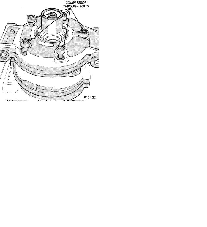
COMPRESSOR FRONT SHAFT SEALÐMODEL 10PA17
REMOVAL
(1)Discharge the refrigerant system.
(2)Remove A/C compressor.
(3)Remove compressor clutch/coil assembly.
(4)Remove compressor through-bolts (Fig. 1).
Fig. 1 Compressor Through-Bolts
(5)Remove front cover by tapping on the outside diameter of the cover with a plastic hammer (Fig. 2).
(6)Remove steel valve plate gasket and O-ring seal and discard (Fig. 3 and 4).
Never reuse cover O-rings or the steel valve plate gaskets.
Fig. 2 Removing Front Cover
Fig. 3 Removing Steel Valve Plate Gasket
(7)Pry out the felt retainer and remove felt from front cover (Fig. 5).
(8)Remove seal snap ring (Fig. 6).
(9)Place compressor front cover on a flat surface with neck of cover facing up. Using a brass drift, press out seal assembly (Fig. 7).
(10)Remove dowel pins, valve plates, and steel valve plate gasket. Discard steel gasket (Fig. 8).
INSTALLATION
(1)Install dowel pins in front compressor body.
(2)Install cleaned valve plates.

Ä |
|
HEATING AND AIR CONDITIONING 24 - 35 |
|
Fig. 4 Removing O-Ring
Fig. 5 Removing Felt Retainer and Felt
Fig. 6 Seal Snap Ring
Fig. 7 Removing Seal
Fig. 8 Disassembling Compressor Front End
(3)Install steel gasket.
(4)Clean crankshaft and coat lightly with refrigerant oil.
(5)Lubricate crankshaft seal seat cavity of front housing with refrigeration oil.
(6)Lubricate crankshaft lip seal and seal O-ring with refrigeration oil. Then install lip seal in front cover using a socket that contacts the outer diameter of the lip seal (Figs. 9 and 10).
(7)Install seal snap ring (Fig. 11).
(8)Lubricate front cover O-ring with refrigeration oil and carefully place it in seal groove.
(9)Install lip seal protector on shaft (Fig. 12).
(10)Install front cover to front compressor body.
(11)Install compressor through-bolts and finger
tighten only. After bolts have been finger tightened, torque to 29 NIm (260 in. lbs.).