

24 - 62 HEATING AND AIR CONDITIONING |
|
Ä |
|
TEST/ACTION
²Check linkages from the mode door actuator for binding.
²Check for proper door travel in the unit.
(5)The computer will do one of two things:
²Will return to the control settings that were selected before the Diagnostic Test was started. This means the test is over. If Failure Codes did not occur, and answers to questions (a), (b), (c), and (d) were YES, the entire system is operating correctly.
²The blower motor will stop and the computer will flash a FAILURE CODE number from 01 through 28. Record the number and then depress the PANEL button to advance to the next test. If the ATC control flashes one or more codes 23 to 28, the digits on the display will flash alternating Zeros. If you do nothing, these codes will remain stored within the ATC control computer. After all repairs have been made erase fault codes. Refer to Erasing Failure Codes 23 through 28 from ATC Control in this section.
Repair all Failure Codes in the order that they have been indicated, and then retest the system. If any blend door test fails, all remaining blend door tests will be skipped. IF any mode door tests fail, all remaining mode door tests will be skipped.
Diagnostic Test can be stopped at any time by depressing any button other than PANEL.
FAILURE CODE DEFINITIONS
Non-computer aided diagnostics should be performed first. Hood of vehicle should be closed during the diagnostic test to keep engine heat from effecting the ambient temperature sensor.
Also refer to the wiring Pin out charts (Figs. 10, 11, 12, 13, 14, or 15).
FAILURE CODE 1
²Involves the wiring or the ATC control head. FAILURE CODES 2, 13, 14, 15, 20, and 23
²Involves the wiring, blend-air door actuator, or the ATC control head.
FAILURE CODES 3, 16, 17, 18, 19, and 24
²Involves the wiring, mode door actuator, or the ATC control head.
FAILURE CODE 4
²Involves the wiring, blend-air door actuator, mode door actuator, fresh/recirc. door actuator, or the ATC control head.
FAILURE CODE 5
²Involves the wiring, fresh/recirc. door actuator, or the ATC control head.
FAILURE CODE 6
²Involves the compressor circuit signal wiring, or the ATC control head.
FAILURE CODE 7
²Involves the blower wiring, power module, or the ATC control head.
FAILURE CODES 8, 21, 22
²Requires replacing the ATC control head. FAILURE CODES 9, and 27
²Involves the wiring, sun sensor, or the ATC control head.
FAILURE CODES 10, and 28
²Involves the wiring, water temperature sensor, or the ATC control head.
FAILURE CODES 11, and 25
²Involves the wiring, ambient temperature sensor, or the ATC control head.
FAILURE CODES 12, and 26
²Involves the wiring, in-car temperature sensor/aspirator, or the ATC control head.
FAILURE CODE SERVICE PROCEDURES
The control keyboard will not function if pins 7, 9, 17, 19, or 20 of the 21-way wiring connector are shorted to battery voltage.
For electrical pin numbers, refer to the wiring Pin out charts (Figs. 10, 11, 12, 13, 14, or 15).
FAILURE CODE 1ÐOUTPUT FAILURE WITH ALL OUTPUTS LOW
(1)Remove pin #2 from 21-way connector on control and retest system. If code 01 does not appear, the control is good.
Disconnect 21-way connector from control. With an ohmmeter, measure the resistance between pin #2 and pin #12 of 21-way. This should be between 2,600 and 2,800 ohms. If yes, the power module is good.
Source of voltage on pin #2 is in the wiring. Repair and retest system.
(2)Remove pin #13 from 21-way connector on control and retest system. If code 01 does not appear, the control is good. Locate source of voltage on pin #13. Repair and retest system.
(3)Remove pin #5 from 21-way connector on control and retest system. If code 01 does not appear, the control is good. Locate source of voltage on pin #5. Repair and retest system.
(4)Remove pin #6 from 21-way connector on control and retest system. If code 01 does not appear, the control is good. Locate source of voltage on pin #6. Repair and retest system.
(5)Remove pin #15 from 21-way connector on control and retest system. If code 01 does not appear, the control is good. Locate source of voltage on pin #15. Repair and retest system.
FAILURE CODE 2ÐBLEND ACTUATOR DRIVE SIGNAL NOT HIGH
If both Failure Codes 2 and 3 occur simultaneously, do both procedures. There is typically only 1 failure.
(1) Disconnect terminal #6 on the ATC control 21way connector and retest the system. Note that removing this terminal may generate additional Failure Codes. Disregard these at this time.

Ä |
|
HEATING AND AIR CONDITIONING 24 - 63 |
|
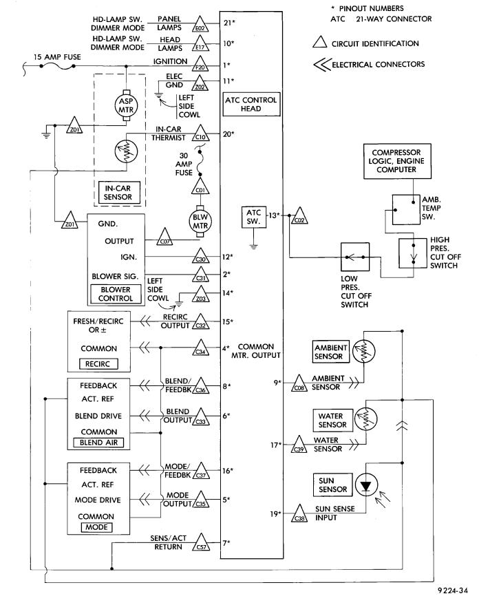
Fig. 10 Pin outs for 21-way Connector at ATC Computer Connector

24 - 64 HEATING AND AIR CONDITIONING |
|
Ä |
|
Fig. 11 Pin outs for 14-way Connector at ATC Harness on A/C Housing

Ä |
|
HEATING AND AIR CONDITIONING 24 - 65 |
|
Fig. 12 Pin outs for 4-Way Connector
Fig. 13 Pin outs for Sun Sensor 2-Way Connector
(2)If Failure Code 2 reappears, replace control.
(3)If code 2 does not reappear, the problem is a shorted blend door actuator motor or a short to ground in circuit 33 (pin #6).
(4) Remove 21-way connector and check for continuity from pin #6 to chassis ground. There should not be any continuity. If continuity is there, repair wiring and retest.

24 - 66 HEATING AND AIR CONDITIONING |
|
Ä |
|
Fig. 14 Pin outs for 6-Way Connector In-Car Sensor and Sun Sensor
(5) Check resistance across pins #6 and #4 of the 21-way for a shorted actuator motor. Resistance should be between 20 and 50 ohms. If not correct, replace actuator.
FAILURE CODE 4ÐACTUATOR DRIVE COMMON SIGNAL NOT HIGH
If both Failure Codes 4 and 5 occur simultaneously, do both procedures. There is typically only 1 failure.
FAILURE CODE 3ÐMODE ACTUATOR DRIVE SIGNAL NOT HIGH
If both failure codes 2 and 3 occur simultaneously, do both procedures. There is typically only 1 failure.
(1)Disconnect terminal #5 on the ATC control 21way connector and retest the system. Removing this terminal may generate additional Failure Codes. Disregard these at this time.
(2)If Failure Code 3 reappears, replace control.
(3)If code 3 does not reappear, the problem is a shorted mode door actuator motor, or a short to ground in circuit #35 (pin #5).
(4)Remove 21-way and check for continuity from pin #5 to chassis ground. There should not be any continuity. If continuity is there, repair wiring and retest.
(5)Check resistance across pins #4 and #5 of the 21-way connector for a shorted actuator motor. Resistance should be between 20 and 50 ohms. If not correct, replace actuator.
(1)Disconnect terminal #4 on the ATC control 21way connector and retest the system. Removing this terminal may generate additional Failure Codes. Disregard these at this time.
(2)If Failure Code 4 reappears, replace control.
(3)If code 4 does not reappear, the problem is a shorted actuator motor or a short to ground in circuit #34 (pin #4).
(4)Remove 21-way connector and check for continuity from pin #4 to chassis ground. There should not be any continuity. If continuity is there, repair wiring and retest.
(5)Check resistance across pins #4 and #5, #4 and #6, and #4 and #15 of the 21-way connector for a shorted actuator motor. Resistance should be between 20 and 50 ohms. If not correct, replace actuator involved.
FAILURE CODE 5ÐFRESH/RECIRC ACTUATOR DRIVE SIGNAL NOT HIGH
If both Failure Codes 4 and 5 occur simultaneously, do both procedures. There is typically only 1 failure.
Ä |
|
HEATING AND AIR CONDITIONING 24 - 67 |
|
Fig. 15 ATC Circuits

24 - 68 HEATING AND AIR CONDITIONING
(1)Disconnect terminal #15 on the ATC control 21-way connector and retest the system. Removing this terminal may generate additional Failure Codes. Disregard these at this time.
(2)If Failure Code 5 reappears, replace control.
(3)If code 5 does not reappear, the problem is a shorted fresh/recirc door actuator motor. It could also be a short to ground in circuit #32 (pin #15).
(4)Remove 21-way connector and check for continuity from pin #15 to chassis ground. There should not be any continuity. If continuity is there, repair wiring and retest.
(5)Check resistance across pins #15 and #4 of the 21-way connector for a shorted actuator motor. Resistance should be between 20 and 50 ohms. If not correct, replace actuator.
FAILURE CODE 6ÐCOMPRESSOR DRIVE SIGNAL NOT HIGH
(1)Disconnect the low pressure cut out switch and retest diagnostics.
(2)If code 6 does not reappear, then the problem is in the A/C signal circuit C02. Check for wiring problem between the low pressure cut out switch and the engine controller, or a bad engine controller.
(3)If code 6 does reappear, remove the 21-way connector from the control and check for a short between pin #13 and chassis ground. This test will check the wire from the control to the low pressure cut out switch for a short to ground.
(4)If pin #13 shows continuity, repair circuit C02 and retest.
(5)If no continuity is shown, replace the ATC control and retest.
FAILURE CODE 7ÐBLOWER DRIVE SIGNAL NOT HIGH
First check the 4-way connector to the power module for correct installation
(1)With the ignition ON, check for ignition voltage to the power module pin #1 from the ATC control. If ignition is present at the power module, proceed to step 3. If not proceed to step 2.
(2)With the 21-way connector still connected and the ignition ON, check for power module ignition feed at the control pin #12. If ignition is not present, replace the control. If ignition voltage is present, repair the open in the wire between the control pin #12 and power module pin #1. Retest system.
(3)Turn ignition OFF and disconnect the 21-way connector. Measure the resistance between pins #2 and #12. The resistance should read between 2,600 and 2,800 ohms. If correct, replace the ATC control. If not correct, proceed to step 4.
(4)Remove the 4-way connector from the power module. Check for continuity between the ATC control pin #2 and power module pin #2. If no continu-
Ä
ity is shown, repair the wire for an open. If continuity is shown, replace the power module and retest.
FAILURE CODE 8ÐA/D CONVERTOR INTERNAL FAILURE
Diagnostics will indicate a Failure Code 8 if the internal reference voltage of the A/D Convertor is not correct. This Failure Code is not serviceable. If a Failure Code 8 occurs, the computer control head must be replaced.
FAILURE CODE 9ÐSUN LOAD SENSOR FAILURE
(1)Unplug the 21-way connector from the control and check pin #19 for continuity to chassis ground. If continuity is present, repair the wire shorted to ground. If no continuity is present, proceed to step 2.
(2)Plug the 21-way connector back in. Remove pin #19 from the 21 way connector and run diagnostics again. If Failure Code 9 is still present, replace the control. If code 9 is not present, replace the sun sensor.
FAILURE CODE 10ÐWATER TEMPERATURE SENSOR FAILURE
(1) Disconnect 21-way connector at control. Measure resistance between pin #17 and pin #7. This value will change with temperature. Refer to Temperature ReferenceÐFailure Code 10 chart.
TEMPERATURE REFERENCEÐFAILURE
CODE 10
(2) Check for continuity between pin #17 and chassis ground. If continuity is present, repair and retest.

Ä
FAILURE CODE 11ÐAMBIENT TEMPERATURE SENSOR FAILURE
(1) Disconnect 21-way connector at control. With an ohmmeter, measure the resistance between pin #9 and pin #7. Refer to the Temperature ReferenceÐFailure Code 11 chart.
TEMPERATURE REFERENCEÐFAILURE
CODE 11
(2) Check for continuity between pin #9 and chassis ground. If continuity is present, repair and retest.
FAILURE CODE 12ÐIN-CAR TEMPERATURE SENSOR/ASPIRATOR FAILURE
(1)Disconnect 21-way connector at control. With an ohmmeter, measure the resistance between pin #20 and pin #7. Refer to Temperature ReferenceÐFailure Code 11 chart for electrical values.
(2)Check for continuity between pin #20 and chassis ground. If continuity is present, repair and retest.
FAILURE CODE 13ÐBLEND DOOR FAILED TO DRIVE TO HEAT POSITION
(1)Check door and linkage for binding.
(2)Disconnect 21-way connector from control head and the 5-way connector from the blend air door actuator. Check continuity between pin #6 of the 21way connector and pin #5 of the 5-way connector. If continuity is shown, go to step 3. If continuity is not shown, repair circuit for an open circuit and retest system.
(3)Plug in the 5-way connector and check for resistance between pins #4 and #6 of the 21-way connector. A resistance of 20-50 ohms should be present. If not, replace actuator. If correct, proceed to step 4.
(4)If steps 1 and 2 indicate no failures, replace the ATC control head.
HEATING AND AIR CONDITIONING 24 - 69
FAILURE CODE 14ÐBLEND DOOR FAILED TO DRIVE TO COLD POSITION
First check the 5-way connector to the blend air door actuator for proper connection
(1)Check door and linkage for binding.
(2)Remove the 21-way connector from the control. With ignition ON, check for ignition voltage between pin #8 of the 21-way connector and chassis ground. If voltage is present, repair circuit for short to ignition voltage. If voltage is not present, proceed to step 3.
(3)Turn ignition OFF. With the 21-way still removed, disconnect the 5-way connector from the blend air door actuator. Check for continuity between pin #8 of the 21-way connector and pin #1 of the 5-way connector. If continuity is not present, repair open circuit. If present, continue to step 4.
(4)Install the 5-way connector back into the blend air door actuator and check for continuity between the pins #7 and #8 of the 21-way connector. If continuity is present, replace the ATC control. If continuity is not present, replace the blend air door actuator.
FAILURE CODE 15ÐBLEND DOOR FEEDBACK SHORTED TO GROUND
(1)Remove the 21-way connector from the control and the 5-way connector from the blend air door actuator.
(2)Check for continuity between pin #8 of the 21way connector and chassis ground. If present, repair circuit for short to ground. If not present, continue to step 3.
(3)Plug in the 5-way connector and measure resistance between pins #7 and #8 of the 21-way connector. If the resistance is less than 10 ohms, replace the actuator. If not, replace the control head.
FAILURE CODE 16ÐMODE DOOR MOVED DURING BLEND DOOR TEST
(1)Remove the 21-way connector from the control and the 5-way connector from the three actuators.
(2)Check for continuity between pin #4 of the 21way connector and pin #4 of each actuator. If continuity is not present for a particular actuator circuit, repair that circuit and retest system. If continuity is present for all circuits, continue to step 3.
(3)Plug in the 5-way connectors and check for resistance between pins #4 and #6 of the 21-way connector for the blend air actuator. Then check pins #4 and #5 of the 21-way for the mode actuator. The resistance should be between 20-50 ohms. If either of the actuators do not pass the resistance tests, replace that particular actuator and retest the system. If both pass the resistance test, replace the ATC control.

24 - 70 HEATING AND AIR CONDITIONING
FAILURE CODE 17ÐMODE DOOR FAILED TO DRIVE TO DEFROST
(1)Disconnect 21-way connector from control head and the 5-way connector from the blend air door actuator. Check continuity between pin #5 of the 21way connector and pin #5 of the 5-way connector. If continuity is present, proceed to step 2. If continuity is not present, repair open circuit and retest system.
(2)Plug in the 5-way connector and check for resistance between pins #4 and #5 of the 21-way connector. A resistance of 20-50 ohms should be present. If not, replace actuator. If correct, proceed to step 3.
(3)If steps 1 and 2 do not indicate any failures, replace the ATC control head.
FAILURE CODE 18ÐMODE DOOR FAILED TO DRIVE TO PANEL
Check the 5-way connector to the mode door actuator for proper installation.
(1)Check the door and linkage for binding.
(2)Remove the 21-way connector from the control. With ignition ON, check for ignition voltage between pin #16 of the 21-way connector and chassis ground. If voltage is present, repair circuit for short to ignition voltage. If voltage is not present, proceed to step 3.
(3)Turn ignition OFF. With the 21-way connector still removed, disconnect the 5-way connector from the mode door actuator. Check for continuity between pin #16 of the 21-way connector, and pin #1 of the 5-way connector. If continuity is not present, repair circuit for an open. If present, continue to step 4.
(4)Install 5-way connector back into the mode door actuator. Then check for continuity between pins #7 and #16 of the 21-way connector. If continuity is present, replace the ATC control. If continuity is not present, replace the mode door actuator.
FAILURE CODE 19ÐMODE DOOR FEEDBACK SHORTED TO GROUND
(1)Remove the 21-way connector from the control, and the 5 way connector from the mode door actuator.
(2)Check for continuity between pin #16 of the 21-way connector and chassis ground. If present, repair circuit for short to ground. If not present, continue to step 3.
(3)Plug in the 5-way connector and measure resistance between pins #7 and #16 of the 21-way connector. If the resistance is less than 10 ohms, replace the actuator. If not, replace the control head.
FAILURE CODE 20ÐBLEND DOOR MOVED DURING MODE DOOR TEST
(1) Remove the 21-way connector from the control and the 5-way connector from the three actuators.
Ä
(2)Check for continuity between pin #4 of the 21way connector and pin #4 of each actuator. If continuity is not present for a particular actuator circuit, repair that circuit and retest system. If continuity is present for all circuits, continue to step 3.
(3)Plug in the 5-way connectors and check for resistance between pins #4 and #6 of the 21-way connector for the blend air actuator. Then check pins #4 and #5 of the 21-way connector for the mode actuator. The resistance should be between 20-50 ohms. If either of the actuators do not pass the resistance tests, replace that particular actuator and retest the system. If both pass the resistance test, replace the ATC control.
FAILURE CODE 21ÐROM CHECK SUM ERROR
During the Diagnostics test, the computer will verify it's own internal program. If it finds any part to be bad, a Failure Code 21 will be set. This Failure Code is not serviceable. If a Fail Code 21 occurs, the ATC Control Module must be replaced.
FAILURE CODE 22ÐCOMPUTER ERROR
If incorrect data is found in the ATC Control computer module, a Failure Code 22 will be set. This Fail Code is not serviceable. If a Failure Code 22 occurs, the ATC Control Module must be replaced.
FAILURE CODE 23ÐBLEND DOOR FEEDBACK FAILED
This Failure Code is set during normal ATC operation. The Failure Code will be set only after the ATC control has been operating for 15 minutes. The control will compensate for the feedback failure immediately upon power up, but the Failure Code will not be set until the time limit has been met.
Failure Code 23 will be stored within the ATC Control, and must be cleared after the failure has been repaired. To clear this Failure Code, refer to Erasing Failure Codes 23 through 28 from ATC Control.
Follow service procedures for Failure Codes 14 and 15 when repairing.
FAILURE CODE 24ÐMODE DOOR FEEDBACK FAILED
This Failure Code is set during normal ATC operation. The Failure Code will be set only after the ATC control has been operating for 15 minutes. The control will compensate for the feedback failure immediately upon power up, but the Failure Code will not be set until the time limit has been met.
Failure Code 24 will be stored within the ATC Control, and must be cleared after the failure has been repaired. To clear this Failure Code, refer to Erasing Failure Codes 23 through 28 From ATC Control.