


CHA PT E R 7
Design Reference Bank
Introduction
Our final chapter contains a useful list of design examples and applications that will give you a good jump start into your future programmable logic designs.
We selected the application examples from a comprehensive list of application notes available from the Xilinx website, as well as extracts from the Xilinx quarterly magazine, the Xcell Journal (To subscribe, click on “Subscribe to Xcell Journal” at www.xilinx.com/publications/xcellonline/).
This section will also give you pointers on where to look for and download code and search for IP from the Xilinx website.
Get the Most out of Microcontroller-Based Designs
Microcontrollers don’t make the world go round, but they most certainly help us get around in the world. You can find microcontrollers in automobiles, microwave ovens, automatic teller machines, VCRs, point-of-sale terminals, robotic devices, wireless telephones, home security systems, and satellites, to name just a few applications.
In the never-ending quest for faster, better, and cheaper products, advanced designers are now pairing CPLDs with microcontrollers to take advantage of the strengths of each.
Microcontrollers are naturally good at sequential processes and computationally intensive tasks, as well as a host of non-time-critical tasks.

PROGRAMMABLE LOGIC DESIGN -- QUICK START HANDBOOK •
CPLDs such as Xilinx CoolRunner devices are ideal for parallel processing, high-speed operations, and applications where lots of inputs and outputs are required.
Although faster and more powerful microcontrollers do exist, 8-bit microcontrollers own much of the market because of their low cost and low power characteristics.
The typical operational speed is around 20 MHz, but some microcontroller cores divide clock frequency internally and use multiple clock cycles per instruction (operations often include fetch-and-execute instruction cycles).
Thus, with a clock division of 2 – with each instruction taking as long as three cycles – the actual speed of a 20 MHz microcontroller is divided by 6. This works out to an operational speed of only 3.33 MHz.
CoolRunner CPLDs are much, much faster than microcontrollers and can easily reach system speeds in excess of 100 MHz. Today, we are even seeing CoolRunner devices with input-to-output delays as short as 3.5 ns, which equates to impressive system speeds as fast as 285 MHz.
CoolRunner CPLDs make ideal partners for microcontrollers, because they not only can perform high-speed tasks, they can perform those tasks with ultralow power consumption.
Xilinx offers free software and low-cost hardware design tools to support CPLD integration with microcontrollers.
The Xilinx CPLD design process is quite similar to that used on microcontrollers, you can quickly learn how to partition your designs across a CPLD and microcontroller to maximum advantage.
So far, a design partition over a microcontroller and a CPLD sounds good in theory, but will it work in the field?
We will devote the rest of this chapter to design examples that show how you can enhance a typical microcontroller design by utilizing the computational strengths of the microcontroller and the speed of a CoolRunner CPLD.
CONVENTIONAL STEPPER MOTOR CONTROL
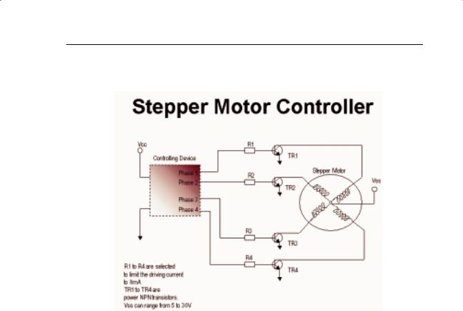
A frequent use of microcontrollers is to run stepper motors. Figure 7-1 depicts a typical four-phase stepper motor driving circuit. The four windings have a common connection to the motor supply voltage (Vss), which typically ranges from 5V to 30V.
• 162
DESIGN REFERENCE BANK
A high-powered NPN transistor drives each of the four phases. (Incidentally, MOSFETs can also be used to drive stepper motors.)
FIGURE 7-1: STEPPER MOTOR CONTROLLER
Each motor phase current may range from 100 mA to as much as 10A. The transistor selection depends on the drive current, power dissipation, and gain.
The series resistors should be selected to limit the current to 8 mA per output to suit either the microcontroller or CPLD outputs. The basic control sequence of a four-phase motor is achieved by activating one phase at a time.
At the low-cost end, the motor rotor rotates through 7.5 degrees per step, or 48 steps per revolution.
More accurate, higher cost versions have a basic resolution of 1.8 degrees per step.
Furthermore, it is possible to half-step these motors to achieve a resolution of 0.9 degrees per step. Stepper motors tend to have a much lower torque than other motors, which is advantageous in precise positional control.
• 163
PROGRAMMABLE LOGIC DESIGN -- QUICK START HANDBOOK •
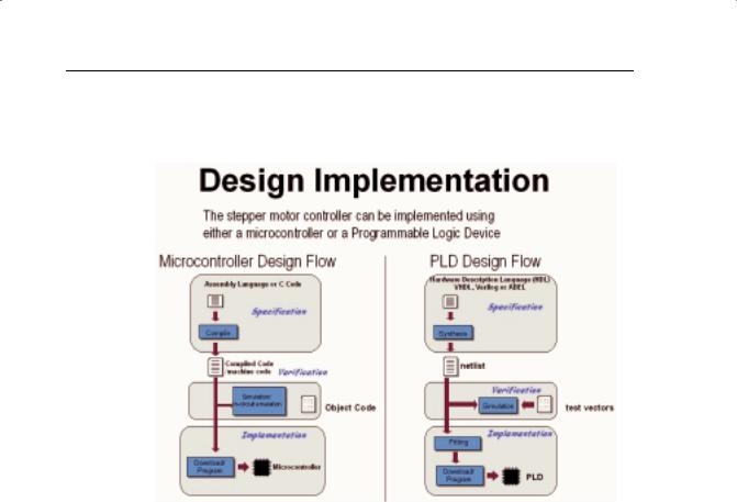
The examples that follow show how either a microcontroller or a CPLD can control stepper motor tasks to varying degrees of accuracy. As Figure 7-2 illustrates, the design flow for both is quite similar.
FIGURE 7-2: DESIGN FLOW COMPARISON
Both flows start with text entry. Assembly language targets microcontrollers; the ABEL hardware description language targets PLDs.
After entering the text “description,” the design is either compiled (microcontroller) or synthesized (PLD). Next, the design is verified by some form of simulation or test.
Once verified, the design is downloaded to the target device – either a microcontroller or PLD. We can then program the devices in-system using an inexpensive ISP cable.
One of the advantages of a PLD over a microcontroller occurs during board-level testing. Using a JTAG Boundary Scan, the PLD can be fully tested on the board. The PLD can also be used as a “gateway” to test the rest of the board’s functionality. After the board-level test is completed, the PLD can then be programmed with the final code in-system via the JTAG port.
Microcontrollers can include monitor debug code internal to the device for limited code testing and debugging. With the advent of flash-based microcontrollers, these can now also be programmed in-system.
• 164