

3D Game Programming All In One (2004)
.pdf98 Chapter 3 ■ 3D Programming Concepts
n o t e
The order that we use to apply the transformations is important. In the great majority of cases, the correct order is scaling, rotation, and then translation. The reason is that different things happen depending on the order.
Figure 3.17 |
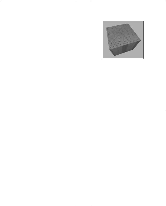
Faces on an irregularly shaped object. |
You will recall that objects are created in object space, then moved into world space. The object's origin is placed at the world origin. When we rotate the object, we rotate it around the appropriate axes with the origin at (0,0,0), then translate it to its new position.
If you translate the object first, then rotate it (which is still going to take place around (0,0,0), the object will end up in an entirely different position as you can see in Figure 3.17.
Rendering
Rendering is the process of converting the 3D mathematical model of an object into an on-screen 2D image. When we render an object, our primary task is to calculate the appearance of the different faces of the object, convert those faces into a 2D form, and send the result to the video card, which will then take all the steps needed to display the object on your monitor.
We will take a look at several different techniques for rendering, those that are often used in video game engines or 3D video cards. There are other techniques, such as ray-casting, that aren't in wide use in computer games—with the odd exception, of course—that we won't be covering here.
In the previous sections our simple cube model had colored faces. In case you haven't noticed (but I'm sure you did notice), we haven't covered the issue of the faces, except briefly in passing.
A face is essentially a set of one or more contiguous co-planar adjacent triangles; that is, when taken as a whole, the triangles form a single flat surface. If you refer back to Figure 3.12, you will see that each face of the cube is made with two triangles. Of course, the faces are transparent in order to present the other parts of the cube.
Team LRN

|
Displaying 3D Models |
99 |
Flat Shading |
|
|
|
|
|
Figure 3.18 provides an example of various face config- |
|
|
urations on an irregularly shaped object. Each face is |
|
|
presented with a different color (which are visible as dif- |
|
|
ferent shades). All triangles with the label A are part of |
|
|
the same face; the same applies to the D triangles. The |
|
|
triangles labeled B and C are each single-triangle faces. |
|
|
When we want to display 3D objects, we usually use |
|
|
some technique to apply color to the faces. The sim- |
|
|
plest method is flat shading, as used in Figure 3.17. A |
|
|
|
|
|
color or shade is applied to a face, and a different color Figure 3.18 Faces on an |
|
|
or shade is applied to adjacent faces so that the user |
irregularly shaped object. |
|
|
|
|
can tell them apart. In this case, the shades were select- |
|
|
ed with the sole criterion being the need to distinguish one face from the other.
One particular variation of flat shading is called Z-flat shading. The basic idea is that the farther a face is from the viewer, the darker or lighter the face.
Lambert Shading
Usually color and shading are applied in a manner that implies some sense of depth and lighted space. One face or collection of faces will be lighter in shade, implying that the direction they face has a light source. On the opposite side of the object, faces are shaded to imply that no light, or at least less light, reaches those faces. In between the light and dark faces, the faces are shaded with intermediate values. The result is a shaded object where the face shading provides information that imparts a sense of the object in a 3D world, enhancing the illusion. This is a form of flat shading known as lambert shading (see Figure 3.19).
Figure 3.19 |
Lambert-shaded |
object. |
|
Gouraud Shading
A more useful way to color or shade an object is called gouraud shading. Take a look at Figure 3.20. The sphere on the left (A) is flat shaded, while the sphere on the right (B) is gouraud shaded. Gouraud shading smoothes the colors by averaging the normals (the vectors that indicate which way surfaces are facing) of the
Figure 3.20 Flat-shaded (A) and gouraudshaded (B) spheres.
Team LRN

100Chapter 3 ■ 3D Programming Concepts
vertices of a surface. The normals are used to modify the color value of all the pixels in a face. Each pixel's color value is then modified to account for the pixel's position within the face. Gouraud shading creates a much more natural appearance for the object, doesn't it? Gouraud shading is commonly used in both software and hardware rendering systems.
Phong Shading
Phong shading is a much more sophisticated—and computation-intensive—technique for rendering a 3D object. Like gouraud shading, it calculates color or shade values for each pixel. Unlike gouraud shading (which uses only the vertices' normals to calculate average pixel values), phong shading computes additional normals for each pixel between vertices and then calculates the new color values. Phong shading does a remarkably better job (see Figure 3.21), but at a substantial cost.
Phong shading requires a great deal of processing for even a simple scene, which is why you don't see phong shading used much in real-time 3D games where frame rate performance is important. However, there are games made where frame rate is not as big an issue, in which case you will often find phong shading used.
Fake Phong Shading
There is a rendering technique that looks almost as good as phong shading but can allow fast frame rates. It's called fake phong shading, or sometimes fast phong shading, or sometimes even phong approximation rendering. Whatever name it goes by, it is not phong rendering. It is useful, however, and does indeed give good performance.
Fake phong shading basically employs a bitmap,
which is variously known as a phong map, a high-
Figure 3.21 Phong-shaded sphere. light map, a shade map, or a light map. I'm sure there are other names for it as well. In any event, the bitmap is nothing more than a generic template
of how the faces should be illuminated (as shown in Figure 3.22).
|
As you can tell by the nomenclature, there is no real con- |
|
sensus about fake phong shading. There are also several |
|
different algorithms used by different people. This diver- |
|
sity is no doubt the result of several people independent- |
|
ly arriving at the same general concept at roughly the |
Figure 3.22 Example of a |
same time—all in search of better performance with |
fake phong highlight map. |
high-quality shading. |
Team LRN
Displaying 3D Models |
101 |
Texture Mapping
Texture mapping is covered in more detail in Chapters 8 and 9. For the sake of completeness, I'll just say here that texture mapping an object is something like wallpapering a room. A 2D bitmap is "draped" over the object, to impart detail and texture upon the object, as shown in Figure 3.23.
Texture mapping is usually combined with one of the
shading techniques covered in this chapter.
Figure 3.23 Texture-mapped
and gouraud-shaded cube.
Shaders
When the word is used alone, shaders refers to shader programs that are sent to the video hardware by the software graphics engine. These programs tell the video card in great detail and procedure how to manipulate vertices or pixels, depending on the kind of shader used.
Traditionally, programmers have had limited control over what happens to vertices and pixels in hardware, but the introduction of shaders allowed them to take complete control.
Vertex shaders, being easier to implement, were first out of the starting blocks. The shader program on the video card manipulates vertex data values on a 3D plane via mathematical operations on an object's vertices. The operations affect color, texture coordinates, elevation-based fog density, point size, and spatial orientation.
Pixel shaders are the conceptual siblings of vertex shaders, but they operate on each discrete viewable pixel. Pixel shaders are small programs that tell the video card how to manipulate pixel values. They rely on data from vertex shaders (either the engine-specif- ic custom shader or the default video card shader function) to provide at least triangle, light, and view normals.
Shaders are used in addition to other rendering operations, such as texture mapping.
Bump Mapping
Bump mapping is similar to texture mapping. Where texture maps add detail to a shape, bump maps enhance the shape detail. Each pixel of the bump map contains information that describes aspects of the physical shape of the object at the corresponding point, and we use a more expansive word to describe this—the texel. The name texel derives from texture pixel.
Bump mapping gives the illusion of the presence of bumps, holes, carving, scales, and other small surface irregularities. If you think of a brick wall, a texture map will provide the shape, color, and approximate roughness of the bricks. The bump map will supply a
Team LRN

102Chapter 3 ■ 3D Programming Concepts
detailed sense of the roughness of the brick, the mortar, and other details. Thus bump mapping enhances the close-in sense of the object, while texture mapping enhances the sense of the object from farther away.
Bump mapping is used in conjunction with most of the other rendering techniques.
Environment Mapping
Environment mapping is similar to texture mapping, except that it is used to represent effects where environmental features are reflected in the surfaces of an object. Things like chrome bumpers on cars, windows, and other shiny object surfaces are prime candidates for environment mapping.
Figure 3.24 Mipmap textures for a stone surface.
Mipmapping
Mipmapping is a way of reducing the amount of computation needed to accurately texture-map an image onto a polygon. It's a rendering technique that tweaks the visual appearance of an object. It does this by using several different textures for the texture-mapping operations on an object. At least two, but usually four, textures of progressively lower resolution are
assigned to any given surface, as shown in Figure 3.24. The video card or graphics engine extracts pixels from each texture, depending on the distance and orientation of the surface compared to the view screen.
Figure 3.25 Receding mipmap textures on a stone surface.
t i p
In the case of a flat surface that recedes away from the viewer into the distance, for pixels on the nearer parts of the surface, pixels from the high-resolution texture are used (see Figure 3.25). For the pixels in the middle distances, pixels from the medium-resolution textures are used. Finally, for the faraway parts of the surface, pixels from the low-resolution texture are used.
Anti-aliasing is a software technique used in graphics display systems to make curved and diagonal lines appear to be continuous and smooth. On computer monitors the pixels themselves aren't curved, but collectively they combine together to represent curves. Using pixels within polygon shapes to simulate curves causes the edges of objects to appear jagged. Anti-aliasing, the technique for smoothing out these jaggies, or aliasing, usually takes the form of inserting intermediatecolored pixels along the edges of the curve. The funny thing is, with textual displays this has the paradoxical effect of making text blurrier yet more readable. Go figure!
Team LRN

Displaying 3D Models |
103 |
Scene Graphs
In addition to knowing how to construct and render 3D objects, 3D engines need to know how the objects are laid out in the virtual world and how to keep track of changes in status of the models, their orientation, and other dynamic information. This is done using a mechanism called a scene graph, a specialized form of a directed graph. The scene graph maintains information about all entities in the virtual world in structures called nodes. The 3D engine traverses this graph, examining each node one at a time to determine how to render each entity in the world. Figure 3.26 shows a simple seaside scene with its scene graph. The nodes marked by ovals are group nodes, which contain information about themselves and point to other nodes. The nodes that use rectangles are leaf nodes. These nodes contain only information about themselves.
Note that in the seaside scene graph, not all of the nodes contain all of the information that the other nodes have about themselves.
Many of the entities in a scene don't even need to be rendered. In a scene graph, a node can be anything. The most common entity types are 3D shapes, sounds, lights (or lighting information), fog and other environmental effects, viewpoints, and event triggers.
Figure 3.26 |
Simple scene graph. |
Team LRN

104Chapter 3 ■ 3D Programming Concepts
When it comes time to render the scene, the Torque Engine will "walk" through the nodes in the tree of the scene graph, applying whatever functions to the node that are specified. It then uses the node pointers to move on to the next node to be rendered.
3D Audio
Audio and sound effects are used to heighten the sense of realism in a game. There are times when the illusion is greatly enhanced by using position information when generating the sound effects. A straightforward example would be the sound generated by a nearby gunshot. By calculating the amplitude—based on how far away the shot occurred— and the direction, the game software can present the sound to a computer's speakers in a way that gives the player a strong sense of where the shot occurred. This effect is even better if the player is wearing audio headphones. The player then has a good sense of the nature of any nearby threat and can deal with it accordingly—usually by massive application of return fire.
The source location of a game sound is tracked and managed in the same way as any other 3D entity via the scene graph.
Once the game engine has decided that the sound has been triggered, it then converts the location and distance information of the sound into a stereo "image" of the sound, with appropriate volumes and balance for either the right or left stereo channel. The methods used to perform these calculations are much the same as those used for 3D object rendering.
Audio has an additional set of complications—things like fade and drop-off or cutoff.
3D Programming
With the Torque Engine, most of the really grubby low-level programming is done for you. Instead of writing program code to construct a 3D object, you use a modeling tool (which we cover in later chapters) to create your object and a few lines of script code to insert the object in a scene. You don't even need to worry about where in the scene graph the object should be inserted—Torque handles that as well, through the use of information contained in the datablocks that you define for objects.
Even functions like moving objects around in the world are handled for us by Torque, simply by defining the object to be of a certain class and then inserting the object appropriately.
The kinds of objects we will normally be using are called shapes. In general, shapes in Torque are considered to be dynamic objects that can move or otherwise be manipulated by the engine at run time.
There are many shape classes; some are fairly specific, like vehicles, players, weapons, and projectiles. Some are more general-purpose classes, like items and static shapes. Many of
Team LRN

3D Programming |
105 |
the classes know how their objects should respond to game stimuli and are able to respond in the game with motion or some other behavior inherent to the object's class definition.
Usually, you will let the game engine worry about the low-level mechanics of moving your 3D objects around the game world. However, there will probably be times while creating a game that you are going to want to cause objects to move in some nonstandard way—some method not defined by the class definition of the object. With Torque, this is easy to do!
Programmed Translation
When an object in 3D world space moves, it is translating its position, in a manner similar to that shown earlier in the discussion about transformations.
You don't, however, absolutely need to use the built-in classes to manipulate shapes in your game world. For example, you can write code to load in an Interior (a class of objects used for structures like buildings) or an Item (a class of objects used for smaller mobile and static items in a game world, like signs, boxes, and powerups). You can then move that object around the world any way you like.
You can also write code to monitor the location of dynamic shapes that are moving around in the world, detect when they reach a certain location, and then arbitrarily move, or teleport, those objects to some other location.
Simple Direct Movement
What we are going to do is select an object in a 3D scene in Torque and then move it from one location to another using some script instructions entered directly into the game console. The first step is to identify the object.
1.In the 3DGPAi1 folder locate the Run Chapter 3 shortcut and double-click it to launch the demo.
2.Click Start.
3.Using the mouse, turn your player-character to the left or right a bit, if necessary, until you have a good view of the pyramid.
4.Press F11. Torque's built-in World Editor will appear. As you move your cursor over the scene, you'll notice it change to a hand icon.
5.Click the hand on the pyramid to select it.
6.Move the cursor over to the right side, and click once on the plus sign to the left of the words "MissionGroup - SimGroup". You will see the list expand, and one of the entries, of the type InteriorInstance, will be highlighted. Take note of the number to the left, which is the object's instance ID. See Figure 3.27 for help, if necessary. The ID I get from the figure is 1359; your result should be the same.
Team LRN

106 Chapter 3 ■ 3D Programming Concepts
7. Press the Tilde ("~") key, and the console will pop open. The console interface allows us to directly type in program code and get immediate results.
8. In the console window, type echo(1353.getTransform() ); and then press the Enter key. Don't forget to include the semi-
Figure 3.27 Finding the pyramid object's instance ID.
colon at the end of the line before you press the Enter key.
You should get a result like 49.2144 -66.1692 0.4 0 0 -1 9.74027, which is the transform of the pyramid. The first three numbers are the XYZ coordinates of the geometric center of the pyramid. The next three are the axis normals, which in this case indicates that the Z-axis is pointing straight up. The final value indicates how much rotation is applied around the rotation axes. We'll look at rotation in more detail a little later. Here, the rotation amount (in degrees) is applied to only the Z-axis.
9.In the console window, type 1353.setTransform("0 0 190 0 0 1 0"); and then press the Enter key.
10.Press the Escape key to remove the console window, and take a look. You will notice that the pyramid has moved.
11.Take the next several minutes to experiment with different transforms. Try rotating the pyramid around different axes or several axes at the same time.
12.When you are done, press the Tilde key to exit the console window, press Escape to exit the World Editor, and then press Escape one more time to exit the game.
t i p
In the little exercise in the "Simple Direct Movement" section, you saw a command that looked like this: echo(1353.getTransform() );. The number 1353 is an object ID, and the getTransform() part is what is called a method of that object. A method is a function that belongs to a specific object class. We'll cover these topics in more detail in a later chapter.
Team LRN

3D Programming |
107 |
Programmed Movement
Now we are going to explore how we can move things in the 3D world using program code. We are going to use the Item class to create an object based on a model of a stylized heart, insert the object in the game world, and then start it slowly moving across the ter- rain—all using Torque Script.
Something to know about the Item class is that Torque defines it as being affected by gravity. So if we insert the object into the scene at some distance above the ground level of the terrain, the object will actually fall to the ground—a little more slowly than it would in the real world, but what the hey! It's a game, after all. Anyway, this also means that we have to specify a mass and a friction drag value in order to prevent the item from sliding down hills if it lands on a slope.
Okay, now—so on to the program. Type the following code module into a file and save the file as 3DGPAi1\CH3\moveshape.cs.
//========================================================================
//moveshape.cs
//
//This module contains the definition of a test shape, which uses
//a model of a stylized heart. It also contains functions for placing
//the test shape in the game world and moving the shape.
//========================================================================
datablock ItemData(TestShape)
// ----------------------------------------------------
// Definition of the shape object
// ----------------------------------------------------
{
// Basic Item properties
shapeFile = "~/data/shapes/items/heart.dts"; mass = 1; //we give the shape mass and
friction = 1; // friction to stop the item from sliding // down hills
};
function InsertTestShape()
// ----------------------------------------------------
//Instantiates the test shape, then inserts it
//into the game world roughly in front of
//the player's default spawn location.
// ----------------------------------------------------
{
Team LRN