

Assembly Language Step by Step 1992
.pdfHere are the assumptions the CPU makes about strings when it executes a string instruction:
•A source string is pointed to by DS:SI.
•A destination string is pointed to by ES:DI.
•The length of both kinds of string is the value you place in CX.
•Data coming from a source string or going to a destination string must pass through register AX.
The CPU can recognize both a source string and a destination string simultaneously, because DS:SI and ES:DI can hold values independent of one another.
However, because there is only one CX register, the length of source and destination strings must be identical when they are used simultaneously, as in copying a source string to a destination string.
One way to remember the difference between source strings and destination strings is by their offset registers. SI means "source index," and DI means "destination index."
10.2 REP STOSW: The Software Machine Gun
The best way to cement all that string background information in your mind is to see a string instruction at work. In this section, I'm going to lay out a very useful video display tool that makes use of the simplest string instruction, STOSW (STOre String by Word). The discussion involves something called a prefix, which I haven't gone into yet. Bear with me for now. We'll discuss prefixes in a little while.
Machine Gunning the Video Display Buffer
The ClrScr procedure we discussed earlier relied on BIOS to handle the actual clearing of the screen. BIOS is very much a black box, and we're not expected to know how it works. (IBM would rather we didn't, in fact....) The trouble with BIOS is that it only knows how to clear the screen to blanks. Some programs (such as Turbo Pascal 6.0) give themselves a stylish, sculpted look by clearing the screen to one of the PC's "halftone" characters, which are character codes 176-178. BIOS can't do this. If you want the halftone look, you'll have to do it yourself. It doesn't involve anything more complex than replicating a single word value (two bytes) into every position in your video refresh buffer. Such things should always be done in tight loops. The obvious way would be to put the video refresh buffer segment into the extra segment register ES, the refresh buffer
offset into DI, the number of words in your refresh buffer into CX, the word value to clear the buffer to into AX, and then code up a tight loop this way:
Clear: |
MOV ES: [DI] , AX |
; |
Copy AX to ES:DI |
INC |
DI |
; |
Bump DI to next *word* in buffer |
INC |
DI |
|
|
DEC |
CX |
; Decrement CX by one position |
|
JNZ |
Clear |
; |
And loop again until CX is 0 |
This will work. It's even tolerably fast. But all of the above code is equivalent to this one single instruction:
REP STOSW Really. Really.
There's two parts to this instruction, actually. As I said, REP is a new type of critter, called a prefix. We'll get back to it. Right now let's look at STOSW. Like all the string instructions, STOSW makes certain assumptions about some CPU registers. It works only on the destination string, so DS and SI are not involved. However, these assumptions must be respected and dealt with:
•ES must be loaded with the segment address of the destination string.
(That is, the string into which the data will be stored.)
•DI must be loaded with the offset address of the destination string.
•CX (the Count register) must be loaded with the number of times the copy of AX is to be stored into the string. Note that this does not mean the size of the string in bytes!
•AX must be loaded with the word value to be stored into the string.
Executing the STOSW Instruction
Once you set up these four registers, you can safely execute a STOSW instruction. When you do, this is what happens:
•The word value in AX is copied to the word at ES:DI.
•DI is incremented by 2, such that ES:DI now points to the next word in memory following the one just written to.
Note that we're not machine gunning here. One copy of AX gets copied to one word in memory. The DI register is adjusted so that it'll be ready for the next time STOSW is executed.
One important point to remember is that CX is not automatically decremented by
STOSW. CX is decremented automatically only if you put the REP prefix in front of STOSW. Lacking the REP prefix, you have to do the decrementing yourself, either explicitly through DEC or through the LOOP instruction, as I'll explain a little later in this chapter.
So you can't make STOSW run automatically without REP. However, you can if you like execute other instructions before executing another STOSW. As long as you don't disturb ES, DI, or CX, you can do whatever you wish. Then when you execute STOSW again, another copy of AX will go out to the location pointed to by ES:DI, and DI will be adjusted yet again. (You have to remember to decrement CX somehow.) Note that you can change AX if you like, but the changed value will be copied into memory. (You may want to do that—there's no law saying you have to fill a string with only one single value.)
However, this is like the difference between a semiautomatic weapon (which fires one round every time you press and release the trigger) and a fully automatic weapon, which fires rounds continually as long as you hold the trigger down. To make STOSW fully automatic, just hang the REP prefix ahead of it. What REP does is beautifully simpleit sets up the tightest of all tight loops completely inside the CPU, and fires copies of AX into memory repeatedly (hence its name), incrementing DI by 2 each time and decrementing CX by 1, until CX is decremented down to 0. Then it stops, and when the smoke clears you'll see that your whole destination string, however large, has been filled with copies of AX.
Man, now that's programming!
The following macro sets up and triggers REP STOSW to clear the video refresh buffer. The Clear macro was designed to be used with the block of video information variables initialized by the VidCheck procedure I described in Chapter 9- It needs to be passed a far pointer (which is nothing more than a a full 32-bit address consisting of a segment and an offset laid end to end) to the video refresh buffer, the word value to be blasted into the buffer, and the size of the buffer in bytes.
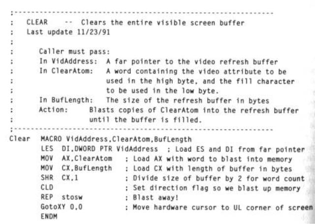
Don't let the notion of a far pointer throw you. It's jargon you're going to hear again and again, and this was a good point to introduce it. A pointer is an address, quite simply. A near pointer is an offset address only, used in conjunction with some value in some segment register that presumably doesn't change. A far pointer is a pointer that consists of both a segment value and an offset value, both of which can be changed at any time, working together. The video refresh buffer is not usually part of your data segment, so if you're going to work with it, you're probably going to have to access it with a far pointer, as we're doing here.
Note that most of Clear is setup work. The LES instruction loads both ES and DI with the address of the destination string. The screen atom (display character plus attribute value) is loaded into AX.
The handling of CX deserves a little explanation. The value in BufLength is the size, in bytes, of the video refresh buffer. Remember, however, that CX is assumed to contain the number of times that AX is to be machine gunned into memory. AX is a word, and a word is two bytes. So each time STOSW fires, two bytes of the video refresh buffer will be written to. Therefore, in order to tell CX how many times to fire the gun, we have to divide the size of the refresh buffer (which is given in bytes) by 2, in order to express the size of the refresh buffer in words.
As I explained in Chapter 9, dividing a value in a register by 2 is easy. All you have to do is shift the value of the register to the right by one bit. This what the SHR CX,1 instruction does: divides CX by 2.
STOSW and the Direction Flag DF
Note the CLD instruction in the Clear macro. I've avoided mentioning it until now to avoid confusing you. Most of the time you'll be using STOSW, you'll want to run it uphill in memory; that is, from a lower memory address to a higher memory address. In Clear, you put the address of the start of the video refresh buffer into ES and DI, and then blast character/attribute pairs into memory at successively higher memory addresses. Each time STOSW fires a word into memory, DI is incremented twice to point to the next higher word in memory.
This is the logical way to work it, but it doesn't have to be done that way. STOSW can just as easily begin at a high address and move downward in memory. On each store into memory, DI can be decremented by two instead.
Which way STOSW fires—uphill toward successively higher addresses, or downhill toward successively lower addresses, is governed by one of the flags in the Flags register. This is the Direction flag (DF). DF's sole job in life is to control the direction of certain instructions that, like STOSW, can move in one of two directions in memory. Most of these (like STOSW) are string instructions.
The sense of DF is this: when DF is set (that is, when DF has the value 1) STOSW and its fellow string instructions work downhill, from higher to lower addresses; when DF is cleared (that is, when DF has the value 0) STOSW and its brothers work uphill from lower to higher addresses. This in turn is simply the direction in which the DI register is adjusted: when DF is set, DI is decremented; when DF is cleared, DI is incremented. The Direction flag defaults to 0 when the CPU is reset. You can change the DF value in one of two ways: with the CLD instruction, or with the STD instruction. CLD clears DF, and STD sets DF. (You should keep in mind when debugging that the POPF instruction can also change DF, by popping an entire new set of flags from the stack into the Flags register.) It's always a good idea to place either CLD or STD right before a string instruction to make sure that your machine gun fires in the right direction!
People sometimes get confused and think that DF also governs whether CX is incremented or decremented by the string instructions. Not so! Nothing in a string instruction ever increments CX! You place a count in CX and it counts down, period. DF has nothing to say about it.
The Clear macro is part of the MYLIB.MAC macro library on the listings diskette for this book. As you build new macro tools, you might place them in MYLIB.MAC as well.
10.3 The Semiautomatic Weapon: STOSW without REP
I chose to show you REP STOSW first because it's dramatic in the extreme. But even more, it's actually simpler to use REP than not to use REP. REP simplifies string processing from the programmer's perspective, because it brings the instruction loop inside the CPU. You can also use the STOSW instruction without REP, but it's a little more work. The work involves setting up the instruction loop outside the CPU, and making sure it's correct.
Why bother? Simply this: with REP STOSW, you can only store the same value into the destination string. Whatever you put into AX before executing REP STOSW is the value that gets fired into memory CX times. STOSW can be used to store different values into the destination string, by firing it semi-automatically, and changing the value in AX between each squeeze of the trigger.
Also, by firing each character individually, you can change the value in DI periodically to break up the data transfer into separated regions of memory instead of one contiguous area as you must with REP STOSW. This may be hard to picture until you see it in action. The SHOWCHAR program listing I'll present a little later will give you a f'rinstance that will make it instantly clear what I mean.
You lose a little time in handling the loop yourself, outside the CPU. This is because there is a certain amount of time spent in fetching the loop's instruction bytes from memory. Still, if you keep your loop as tight as you can, you don't lose a lot of speed.
Who Decrements CX?
Early in my experience with assembly language, I recall being massively confused about where and when the CX register was decremented when using string instructions. It's a key issue, especially when you don't use the REP prefix.
When you use REP STOSW (or REP with any of the string instructions) CX is decremented automatically, by 1, for each memory access the instruction makes. And once CX gets itself decremented down to 0, REP STOSW detects that CX is now 0, and stops firing into memory. Control then passes down to the next instruction in line. But take away REP, and the automatic decrementing of CX stops. So, also, does the

automatic detection of when CX has been counted down to 0.
Obviously, something has to decrement CX, since CX governs how many times the string instruction accesses memory. If STOSW doesn't do it—you guessed it—you have to do it somewhere else, with another instruction.
The obvious way to decrement CX is to use DEC CX. And the obvious way to determine if CX has been decremented to 0 is to follow the DEC CX instruction with a JNZ (Jump if Not Zero) instruction. JNZ tests the zero flag (ZF), and jumps back to the STOSW instruction until ZF becomes true. And ZF becomes true when a DEC instruction causes its operand (here, CX) to become 0.
The LOOP Instructions
With all that in mind, consider the following assembly-language instruction loop:
Ignore the block of instructions in the middle for the time being. What they do is what I suggested could be done a little earlier: change AX in between each store of AX into memory. I'll explain in detail shortly. Look instead (for now) to see how the loop runs. STOSW fires, AX is modified, and then CX is decremented. The JNZ instruction tests to see if the DEC instruction has forced CX to 0. If so, ZF is set, and the loop will terminate. But until ZF is set, the jump is made to the label DoChar, where STOSW fires yet again.
There is a simpler way, using a new instruction: LOOP. The LOOP instruc-tion combines the decrementing of CX with a test and jump based on ZF. It looks like this:
DoChar: |
STOSW |
; Note that there's no REP prefix! |
ADD |
AL,'1' |
; Bump the character value in AL up by 1 |
AAA |
|
; Adjust AX to make this a BCD addition |
ADD |
AL,'0' |
; Basically, put binary 3 in AL's |
high nibble |
MOV |
AH,07 |
; Make sure our attribute is still 7 |
|
LOOP |
DoChar |
; Go back & do another char until |
CX goes to 0 |
The LOOP instruction first decrements CX by 1. It then checks ZF to see if the decrement operation forced CX to 0. If so, it falls through to the next instruction. If not (that is, if ZF remains 0, indicating that CX was still greater than 0) LOOP branches to the label specified as its operand.
So the loop keeps looping the LOOP until CX counts down to 0. At that point, the loop is finished, and execution continues with the next instruction following the loop.
Displaying a Ruler on the Screen
As a useful demonstration of when it makes sense to use STOSW without REP (but with LOOP) let me offer you another item for your video toolkit.
The Ruler macro shown below displays a repeating sequence of ascending digits, from 1, at some selectable location on your screen. In other words, you can display a string of digits like this at the top of a window:
123456789012345678901234567890123456789012345678901234567890
allowing you to determine where in the horizontal dimension of the window a line begins or some character falls. The Ruler macro allows you to specify how long the ruler is, in digits, and where on the screen it will be displayed. A call to Ruler would look like this:
Ruler VidOrigin,20,80.l5,5
This invocation (assuming you had defined VidOrigin to be the address of the start of the video refresh buffer in your machine) places a 20-character long ruler at position 15,5. The 80 argument indicates to Ruler that your screen is 80 characters wide. If you had a wider or narrower text screen, you would have to change the argument to reflect the true width of your screen in text mode.
Don't just read the code inside Ruler! Load it up into a copy of EAT5.ASM, and display some rulers on the screen. You don't learn half as much by just reading assembly code as you do by loading and using it!
Over and above the LOOP instruction, there's a fair amount of new assembly technology
at work here that could stand explaining. Let's detour from the string instructions for a bit and take a closer look.
Simple Multiplies with IMUL
Ruler can put its ruler anywhere on the screen, using the position passed as ScreenX and ScreenY. It's not using GotoXY, either. It's actually calculating a position in the video refresh buffer where the ruler characters must be placed— and then uses STOSW to place them there.
Locations in the video refresh buffer are always expressed as offsets from a single segment address that is either B000H or B800H. The algorithm for determining the offset in bytes for any given X and Y value looks like this:
Offset = ((Y X width in characters of a screen line) + X) x 2
Pretty obviously, you have to move Y lines down in the screen buffer, and then move X bytes over from the left margin of the screen to reach your X,Y position.
; |
RULER |
Displays a "1234567890"-style ruler on screen |
;Last update 11/25/91
;Caller must pass:
;In VidAddress: The address of the start of the video buffer
;In Length: The length of the ruler to be displayed
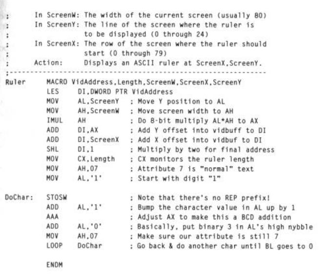
The trickiest part of implementing the algorithm lies in multiplying the Y value by the screen width. There is an instruction to do the job, IMUL, but it's a little quirky and (as assembly instructions go) not very fast.
It is, however, fast enough for what we're doing here, which is just positioning the ruler somewhere on the screen. The positioning only needs to be done once, not many times within a tight loop. So even if IMUL is slow as instructions go, when you only need to use it to set something else up, it's certainly fast enough.
IMUL always operates in conjunction with the AX register. In every case, the destination for the product value is AX, or else AX and DX for products larger than 32,767.
On the 8086/8088 there are basically two variations on IMUL, and the difference depends on the size of the operands. If you are multiplying two 8-bit quantities, you can put one in AL and the other in some 8-bit register or memory location. The product will be placed in AX. If you are multiplying two 16-bit quantities, one can be placed in AX and one in a 16-bit register or memory location. The product from multiplying two 16-bit