

Assembly Language Step by Step 1992
.pdfquantities is too large to fit in a single 16-bit register, so the low-order 16 bits are placed in AX, and the high-order 16 bits are placed in DX. You have no control over the destination; it's either AX or AX:DX. Also, one of the operands must be in AL (for 8-bit multiplies) or AX (for 16-bit multiplies.) You have no control over that; it's impossible to multiply (for example) CX x BX, or DX x DS:[BX].
One very common bug you may commit when using IMUL is simply forgetting that when given 16-bit operands, IMUL changes the value in DX. The easiest way to avoid this problem is to use IMUL in its 8-bit mode whenever possible, which is when both multiplier and multiplicand are less than 256. If either operand is 16 bits in size, DX will be altered.
Here are some examples of the various legal forms of IMUL:
IMUL |
BYTE PTR [BX] |
; multiplies AL x byte at DS:[BX] |
IMUL |
BH |
: multiplies AL x BH |
IMUL |
WORD PTR [BX] |
; multiplies AX x word at DS:[BX] |
IMUL |
BX |
: multiplies AX x BX |
In the first two lines, the destination for the product is AX. In the second two lines, the destination for the product is DX:AX
IMUL sets two flags in those cases where the product is larger than the two operands. The flags involved are the Carry flag (CF) and the Overflow flag (OF). For example, if you're multiplying two 8-bit operands and the product is larger than 8 bits, both CF and OF will be set. Otherwise, the two flags will be cleared.
Now, why the final multiplication by 2? Keep in mind that every character position in the screen buffer is represented by two bytes: One character byte and one attribute byte. So moving X characters from the left margin actually moves X x 2 bytes into the screen buffer. You might think of an 80-character line on the screen as being 80 characters long, but it's actually 160 characters long in the screen buffer, to account for the "invisible" attribute bytes. Multiply-ing by 2 is done using the SHL instruction (shift DI to the left by one bit). As I explained in Chapter 9, this is exactly the same as multiplying DI by 2.
The Limitations of Macro Arguments
There's another problem you will eventually run into if you're like most people. Given the macro header for Ruler
Ruler |
MACRO VidAddress,Length,ScreenW,ScreenX,ScreenY |
you might be tempted to write something like this:
MOV AL,ScreenY IMUL ScreenW
No go! The assembler will call you on it, complaining of an illegal immediate. What went wrong? You can freely use constructions like these:
MOV AL.ScreenY
ADD DI,ScreenX
CMP AL,Length
All of these use arguments from the macro header. So what's that assembler complaining about? The problem here is that the IMUL instruction cannot work with immediate operands. And this isn't just a problem with IMUL: all instructions that cannot work with immediate operands will reject a macro argument under these circumstances.
And "these circumstances" involve the way that the macro is invoked. In the test file RULER.ASM, you'll see the following line, which invokes the macro to display a ruler:
Ruler VidOrigin,20,80,50,10 ; Draw ruler
Except for the video origin address argument, all of these arguments are numeric literals. A numeric literal, when used in an assembly-language instruction, is called immediate data. When the macro is expanded, the argument you pass to the macro is substituted into the actual instruction that uses a macro argument, just as you passed it to the macro. In other words, if you pass the value 10 in the ScreenY argument of the instruction MOV AL,ScreenY, the instruction becomes MOV AL,10 once the macro is expanded by the macro assembler. Now, MOV AL,10 is a completely legal instruction. But if you pass the literal value 80 in the ScreenW argument, you cannot use IMUL ScreenW, because after expansion this becomes IMUL 80, which is not a legal instruction. IMUL does not operate on immediate data!
The problem is not that you're using macro arguments with IMUL. The problem is that you're passing a numeric literal in a macro argument to an instruction that doesn't work with immediate data.
What you have to remember (especially if you're familiar with languages like Pascal) is that macro arguments are not high-level language procedure parameters passed on the stack. They are simply text substitutions. If you had defined a variable in memory called
ScreenWidth using DB, stored the value 80 in it, and then passed ScreenWidth to Ruler as a macro argument, things would be different:
Ruler VidOrigin,20,ScreenWidth,50,10 ; Draw ruler
In this case, you could use the instruction IMUL ScreenW in Ruler, because IMUL ScreenW would be expanded to IMUL ScreenWidth, which is legal because ScreenWidth is a memory location.
I wrote Ruler as I did so that you could use numeric literals when invoking Ruler. Using literals saves memory by making memory variables unnecessary, and if you'd prefer to define a meaningful name for the screen width rather than hard coding the value 80 in the source (which is unwise) you can define a symbol called ScreenWidth as an equate. Equates are a little like miniature macros, and I'll deal with them a little later in this chapter.
Adding ASCII Digits
Once the correct offset is placed in the buffer for the ruler's beginning is calculated in DI, (and once we set up initial values for CX and AX) we're ready to start making rulers. Immediately before the STOSW instruction, we load the ASCII digit '1' into AL. Note that the instruction MOV AL,'l' does not move the value 01 into AL! '1' is an ASCII character, and the character '1' (the "one" digit) has a numeric value of 31H, or 49 decimal.
This becomes a problem immediately after we store the digit '1' into video memory with STOSW. After digit '1' we need to display digit '2', and to do that we need to change the value stored in AL from T to '2'.
Ordinarily, you can't just add '1' to '1' and get '2'. Adding 31H and 31H will give you 62H, which (when seen as an ASCII character) is lowercase letter 'b', not '2'! However, in this case the 8086/8088 instruction set comes to the rescue, in the form of a somewhat peculiar instruction called AAA, (Adjust AL after BCD Addition).
What AAA does is allow us, in fact, to "add" ASCII character digits rather than numeric values. AAA is one of a group of instructions called the BCD instructions, so called because they support arithmetic with binary coded decimal (BCD) values. BCD is just another way of expressing a numeric value, somewhere between a pure binary value like 01 and an ASCII digit like '1'. A BCD value is a 4-bit value, occupying the low nybble of a byte. It expresses values between 0 and 9 only. It's possible to express values greater than 9 (from 9 through 15, actually) in four bits, but those additional values are not valid
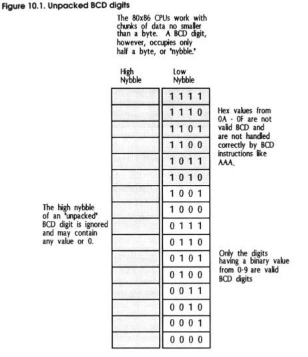
BCD values. See Figure 10.1.
The value 31H is a valid BCD value, because the low nybble contains 1. Because BCD is a 4-bit numbering system, the high nybble (which in the case of 31H contains a 3) is ignored. In fact, all of the ASCII digits from '0' through '9' can be considered legal BCD values, because in each case the characters' low four bits contain a valid BCD value. The 3 stored in the high four bits of each digit is ignored.
So if there were a way to perform BCD addition on the 86-family CPU, adding ASCII digits '1' and '1' would indeed give us '2' because '1' and '2' can be manipulated as legal
BCD values.
AAA (and several other instructions I don't have room to discuss here) give us that ability to perform BCD math. The actual technique may seem a little odd, but it does work. AAA is a sort of a fudge factor, in that you execute AAA after performing an addition using the "normal" addition instruction ADD. AAA takes the results of the ADD instruction and forces them to "come out right" in terms of BCD math.
AAA basically does these two things:
•It forces the value in the low four bits of AL (which could be any value from 0 through F) to a value between 0 and 9 if it was greater than 9.
This is done by adding 6 to AL and then forcing the high nybble of AL to 0. Obviously, if the low nybble of AL contains a valid BCD digit, the digit in the low nybble is left alone.
•If the value in AL had to be adjusted, the adjustment indicates that there was a carry in the addition, and that AH was incremented. Also, the Carry flag (CF) is set
to 1, as is the Auxiliary carry flag (AF). Again, if the low nybble of AL contained a valid BCD digit when AAA was executed, AH is not incremented, and the two carry flags are cleared (forced to 0) rather than set.
AAA thus facilitates base 10 (decimal) addition on the low nybble of AL. After AL is adjusted by AAA, the low nybble contains a valid BCD digit and the high nybble is 0. (But note well that this will be true only if the addition that preceded AAA was executed on two valid BCD operands!)
This allows us to add ASCII digits like T and '2' using the ADD instruction. Ruler does this immediately after the STOSW instruction:
ADD |
AL,' I ’ |
; Bump the character value in AL up by 1 |
AAA |
|
; Adjust AX to make this a BCD addition |
If prior to the addition, the contents of AL's low nybble were 9, adding '1' would make the value A, which is not a legal BCD value. AAA would then adjust AL by adding 6 to AL and clearing the high nybble. Adding 6 to OA would give 10, so once the high nybble is cleared the new value in AL would be 00. Also, AH would have been incremented by 1.
In Ruler we're not adding multiple columns, but instead are simply "rolling over" a count in a single column, and displaying the number in that column to the screen. Therefore we just ignore the incremented value in AH and use AL alone.
Adjusting AAA's Adjustments
There is one problem: AAA clears the high nybble to 0. This means that adding ASCII digits T and T doesn't quite equal '2', the displayable digit. Instead, AL becomes 02, which in ASCII is the dark "smiley face" character. To make AL a displayable ASCII digit again, we have to add 30H to AL. This is easy to do: Just add '0' to AL. The ASCII digit '0' has a numeric value of 30H, so adding '0' takes 02H back up to 32H, which is the numeric equivalent of the ASCII digit '2'. This is the reason for the ADD AL,'0' instruction that immediately follows AAA.
There's a lot more to BCD math than what I've explained here. When you want to perform multiple-column BCD math, you have to take carries into account, which involves the Auxiliary Carry flag (AF). There are also the AAD, AAM, and AAS instructions for adjusting AL after BCD divides, multiplies, and subtracts, respectively. The same general idea applies: all the BCD adjustment instructions force the standard binary arithmetic instructions to "come out right" for BCD operands.
And yet another problem: AAA increments AH whenever it finds a value in the low nybble of AL greater than 9. In Ruler, AH contains the text attribute we're using to display our ruler, and if AH is incremented, the attribute will change and we'll end up displaying parts of the ruler in different colors. This is why we have to do one last adjustment to AAA's adjustments: we must reassert our desired text attribute in AH, each time we change the ASCII digit in AL.
An interesting thing to do is comment out the ADD AL,'0' instruction in the Ruler macro and then run the RULER.ASM test program. Another interesting thing to do (especially if you work on a color screen) is to comment out the MOV AH,07 instruction in Ruler and then run RULER.ASM. Details count, big time!
Ruler's Lessons
The Ruler macro is a good example of using STOSW without the REP prefix. We have to change the value in AX every time we store AX to memory, and thus can't use REP STOSW. Note that nothing is done to ES:DI or CX while changing the digit to be displayed, and thus the values stored in those registers are held over for the next execution of STOSW. Ruler is a good example of how LOOP works with STOSW to adjust CX downward and return control to the top of the loop. LOOP, in a sense, does outside the CPU what REP does inside the CPU: adjust CX and close the loop. Try to keep that straight in your head when using any of the string instructions!
10.4 Storing Data to Discontinuous Strings
Sometimes you have to break the rules. Until now I've been explaining the string instructions under the assumption that the destination string is always one continuous sequence of bytes in memory. This isn't necessarily the case. In addition to changing the value in AX between executions of STOSW, you can change the destination address as well. The end result is that you can store data to several different areas of memory within a single very tight loop.
Displaying an ASCII Table in a Big Hurry
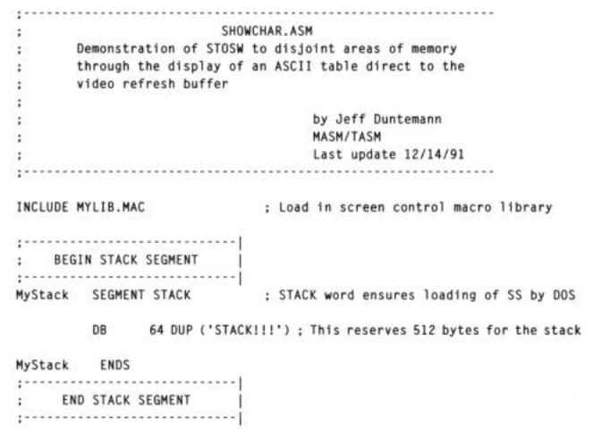
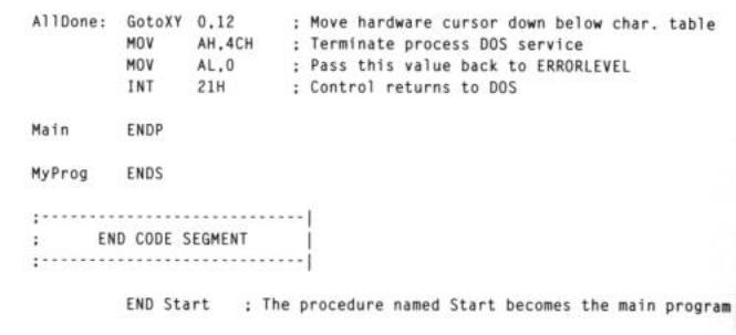
I've created a small demo program to show you what I mean. It's not as useful a tool as the Ruler macro, but it makes its point and is easy to understand. The SHOWCHAR program clears the screen and shows a table containing all 256 ASCII characters, neatly displayed in four lines of 64 characters each. The table includes the "undisplayable" ASCII characters corresponding to the control characters whose values are less than 32. They are displayable from SHOWCHAR because the program writes them directly into video memory. Neither DOS nor BIOS are "aware" of the display of the control characters, so they have no opportunity to interpret or filter out those characters with special meanings.
SHOWCHAR.ASM introduces a number of new concepts and instructions, all related to program loops. (String instructions like STOSW and program loops are intimately related.) Read over the main body of the SHOWCHAR.ASM program carefully. We'll go over it idea by idea through the next several pages.
The Nature of Equates
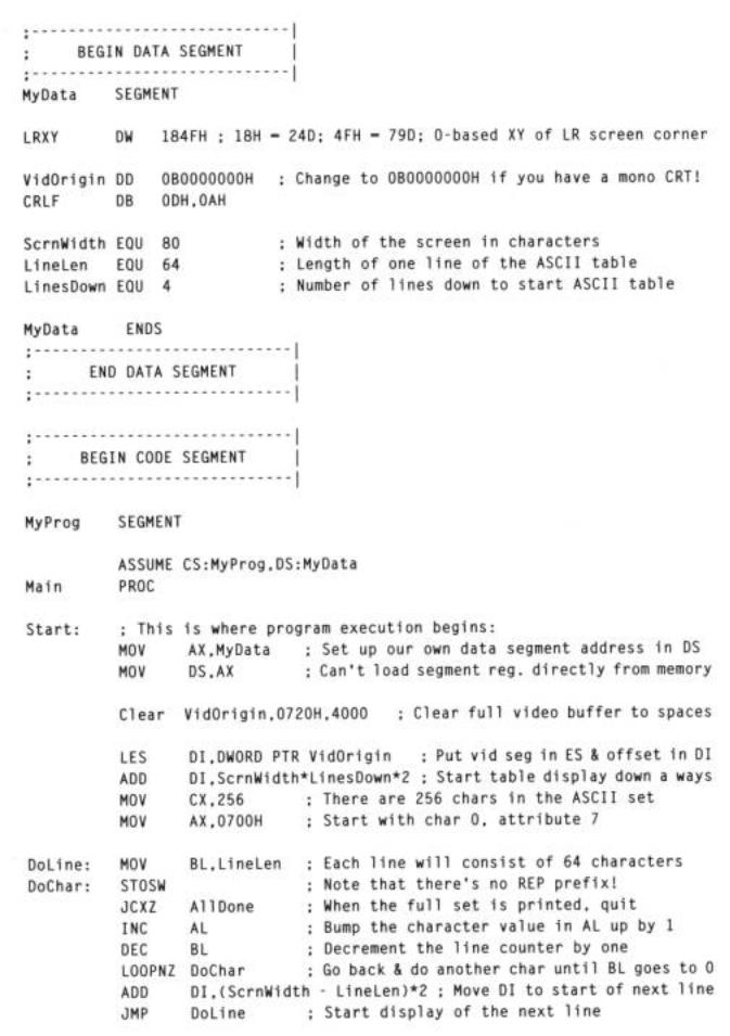
You might remember (and it wouldn't hurt to go back and take another look) how we calculated the offset from the beginning of the video refresh buffer to the memory location corresponding to an arbitrary X,Y position on the screen. We used the ADD instruction, along with the SHL instruction to multiply by 2. There is another way to perform calculations of that general sort in assembly work: let the assembler do them, while the program is being assembled. Take a look at the line below, lifted from
SHOWCHAR.ASM:
ADD |
DI ,ScrnWidth*LinesDown*2 ; Start table display down a ways |
This is new indeed. What can we make of this? What sort of an operand is
ScrnWidth*LinesDown*2?
The answer is that it's a simple integer operand, no different from the value 12, 169, or 15324.
The key is to go back to SHOWCHAR and find out what ScrnWidth and LinesDown are. You might have thought that these were variables in memory, defined with the DW directive. Instead, they're something we haven't really discussed in detail until now: equates. Equates are defined with the EQU operator, and if you find yourself confused over the differences between EQU and DW, don't despair. It's an easy enough thing to do.
One road to understanding harkens back to the Pascal language. What is the difference