

Assembly Language Step by Step 1992
.pdfThat's the reason that we haven't done a lot of instruction arranging in this book up until now, here that we are on the third-to-last chapter. I've found that machine instructions aren't the most important part of assembly-language programming. What's most important is understanding your machine and your tools, and how everything fits together. Higher-level languages like Pascal and Modula-2 hide much of those essential details from you. In assembler you must see to them yourself. For some reason, authors of previous "beginner" books on assembly language haven't caught on to this fact.
This fact (in fact) was the major motivation for my writing this book.
If you've digested everything I've said so far, however, you're ready to get in and understand the remainder of the 8086/8088 instruction set. I won't teach it all in this book, but the phrase "ready to understand" is germane. You can now find yourself a reference and learn what instructions I don't cover on your own. The skills you need to build programming skills are now yours, and if this book has accomplished that much, I'd say it's accomplished a lot.
So let the fun begin.
9.1 Bits is Bits (and Bytes is Bits)
Assembly language is big on bits.
Bits, after all, are what bytes are made of, and one essential assembly-language skill is building bytes and taking them apart again. A technique called bit mapping is widely used in assembly language. Bit mapping assigns special meanings to individual bits within a byte to save space and squeeze the last little drop of utility out of a given amount of memory.
There is a family of instructions in the 8086/8088 instruction set that allow you to manipulate the bits within the bytes by applying Boolean logical operations to the bytes on a bit-by-bit basis. These bitwise logical instructions are: AND, OR, XOR, and NOT. Another family of instructions allows you to slide bits back and forth within a single byte or word. The most commonly used shift/rotate instructions are: ROL, ROR, RCL, RCR, SHL, and SHR. (There are a few others that I will not be discussing in this book.)
Bit Numbering
Dealing with bits requires that we have a way of specifying which bits we're dealing with. By convention, bits in assembly language are numbered, starting from 0, at the

least significant bit in the byte, word, or other item we're using as a bit map. The least significant bit is the one with the least value in the binary number system. (Return to Chapter 1 and reread the material on base 2 if that seems fuzzy to you.) It's also the bit on the far right, if you write the value down as a binary number.
It works best as a visual metaphor. See Figure 9.1.
When you count bits, start with the bit on the right, and number them from 0.
"It's the Logical Thing to Do, Jim ..."
Boolean logic sounds arcane and forbidding, but remarkably, it reflects the realities of ordinary thought and action. The Boolean operator AND, for instance, pops up in many of the decisions you make every day of your life. For example, to write a check that doesn't bounce, you must have money in your checking account AND checks in your checkbook. Neither alone will do the job. ("How can I be overdrawn?" goes the classic question, "I still have checks in my checkbook!) You can't write a check you don't have, and a check without money behind it will bounce. People who live out of their checkbooks (and they always end up ahead of me in the checkout line at Safeway) must use the AND operator frequently.
When mathematicians speak of Boolean logic, they manipulate abstract values called
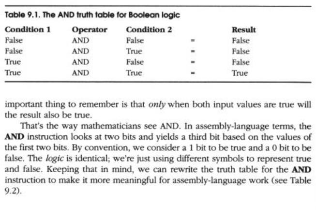
true and false. The AND operator works like this. Condition l AND Condition 2 will be considered true if both Condition l and Condition 2 are true. If either condition is false, the result will be false.
There are in fact four different combinations of the two input values, so logical operations between two values are usually summarized in a form called a truth table. The truth table for the AND operator is shown in Table 9.1.
There's nothing mysterious about the truth table. It's just a summary of all possibilities of the AND operator as applied to two input conditions. The
The AND Instruction
The AND instruction embodies this concept in the 8086/8088 instruction set. The AND instruction performs the AND logical operation on two bytes or two words (depending on how you write the instruction) and replaces its first operand with the result of the operation. (By first, I mean the operand closest to the mnemonic.) In other words, if you write this instruction
AND AL, BL
the CPU will perform a gang of eight bitwise AND operations on the 8 bits in AL and BL. Bit 0 of AL is ANDed with bit 0 of BL, bit 1 of AL is ANDed with bit 1 of BL, and

so on. Each AND operation generates a result bit, and that bit is placed in the first operand (here, AL) after all eight AND operations occur. This is a common thread among machine instructions that perform some operation on two operands and produce a result: the result replaces the first operand.
Masking Out Bits
A major use of the AND instruction is to isolate one or more bits out of a byte value or a word value. The term isolate here simply means to set all unwanted bits to a reliable 0 value. As an example, suppose we are interested in testing bits 4 and 5 of a value to see what those bits are. To do that, we have to be able to ignore the other bits (bits 0 through 3 and 6 through 7) and the only way to safely ignore bits is to set them to 0.
AND is the way to go. We set up a bit mask in which the bit numbers that we want to inspect and test are set to 1, and the bits we wish to ignore are set to 0. To mask out all bits but bits 4 and 5, we must set up a mask in which bits 4 and 5 are set to 1, with all other bits at 0. This mask in binary is 00110000B, or 30H in hex. (To verify it, count the bits from the right hand end of the binary number, starting with 0.) This bit mask is then ANDed against the value in question. Figure 9.2 shows this operation in action, with the 30H bit mask just described, and an initial value of 9DH.
The three binary values involved are shown laid out vertically, with the LSB (the righthand end) of each value at the top. You should be able to trace each AND operation and verify it by looking at Table 9.2.
The end result is that all bits except 4 and 5 are guaranteed to be 0 and can thus be safely ignored. Bits 4 and 5 could be either 0 or 1. (That's why we need to test them; we don't know what they are.) With the initial value of 9DH, bit 4 turns out to be a 1, and bit 5 turns out to be a 0. If the initial value were something else, bits 4 and 5 could both be 0, both 1, or some combination of the two.
Don't forget: the result of the AND operation replaces the first operand after the operation is complete.

For an example of the AND instruction in operation isolating bits in a word, look ahead to the Byte2Str procedure .
The OR Instruction
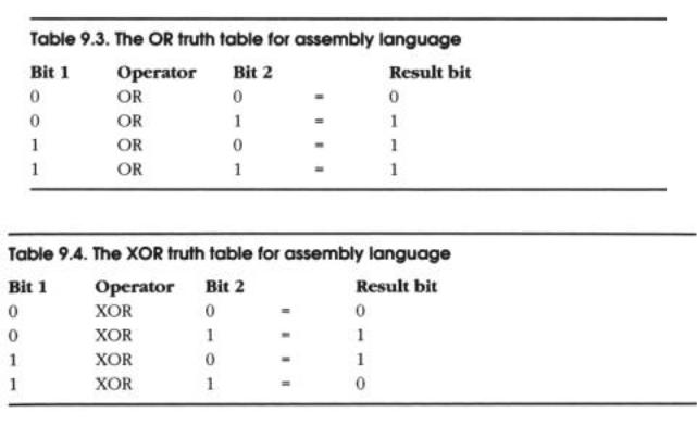
Closely related to the AND logical operation is OR, which, like the AND logical operation, has an embodiment with the same name in the 86-family instruction set. Structurally, the OR instruction works identically to AND. Only its truth table is different: while AND requires that both its operands be 1 for the result to be 1, OR is satisfied that at least one operand has a 1 value. The truth table for OR is shown in Table 9.3.
Because it's unsuitable for isolating bits, OR is used much more rarely than AND
.
The XOR Instruction
In a class by itself is the exclusive OR operation, embodied in the XOR instruction. XOR, again, does in broad terms what AND and OR do: it performs a logical operation on two operands, and the result replaces the first operand. The logical operation, however, is exclusive or, meaning that the result is 1 only if the two operands are different. (1 and 0 or 0 and 1.) The truth table for XOR should make this slippery notion a little clearer (see Table 9.4).
Look this over carefully! In the first and last cases, where the two operands are the same, the result is 0. In the middle two cases, where the two operands are different, the result is 1.
Some interesting things can be done with XOR, but most of them are a little arcane for a beginner's book. I will show you one handy XOR trick, however: "XORing" any value against itself yields 0. Furthermore, putting 0 in a register by XORing the register against itself is faster than putting a 0 in the register by MOVing in a 0 as immediate data.
That is, both of these instructions accomplish the same thing:
mov AL,0 xor AL,AL
However, if you're running an 8086 or 8088 processor, the first instruction uses four machine cycles, while the second uses only three. That's not a tremendous difference (though purists will argue that it represents a 25% improvement) but there are times in assembly language where every machine cycle counts!
How this trick works should be clear from reading the truth table, but to drive it home I've laid it out in Figure 9.3.
Follow each of the individual XOR operations across the figure to its result value. Because each bit in AL is XORed against itself, in every case the XOR operations happen between two operands that are identical. Sometimes both are 1, sometimes both are 0, but in every case the two are the same. With the XOR operation, when the two operands are the same, the result is always 0. Voila! 0 in a register in three cycles flat.
The NOT Instruction
Easiest to understand of all the bitwise logical instructions is NOT. The truth table for the NOT instruction (Table 9.5) is pretty simple because NOT only takes one operand. And what it does is simple as well: NOT takes the state of each bit in its single operand and changes it to its opposite state. What was 1 becomes 0 and what was 0 becomes 1.

Segment Registers Don't Respond to Logic!
One limitation of the segment registers CS, DS, SS, and ES is that they cannot be used with any of the bitwise logical instructions. If you try, the assembler will hand you an "Illegal use of segment register" error. If you need to perform a logical operation on a segment register, you must first copy the segment register's value into one of the nonsegment registers (AX, BX, CX, DX, BP, SI, and DI); perform the logical operation on the new register, and then copy the result back into the segment register.
Table 9.5. The NOT truth table
Bit |
Operator |
Result bit |
0 |
XOR |
1 |
1 |
XOR |
0 |
9.2 Shifting Bits
The other way of manipulating bits within a byte is a little more straightforward: you shift the bits to one side or the other. There are a few wrinkles to the process, but the simplest shift instructions are pretty obvious: the SHL instruction Shifts its operand Left, whereas the SHR instruction Shifts its operand Right.
All of the shift instructions (including the slightly more complex ones I'll describe a little later) have the same general form, illustrated here by the SHL instruction:
SHL <register/memory>,<count>
The first operand is the target of the shift operation; that is, the value that you're going to be shifting. It can be register data or memory data, but not immediate data. The second operand specifies the number of bits by which to shift.
Shift by What?
The <count> operand is a little peculiar. It can be one of two things: the literal digit 1, or else the register CL. (Not CX!) If you specify the count as 1, then the shift will be by one bit. If you wish to shift by more than one bit at a time, you must load the shift count into register CL. Counting things is CX's (and hence CL's) hidden agenda; it counts shifts, loops, string elements, and a few other things. That's why it's sometimes called the count register ("C" for "count").
Although you can load a number as large as 255 into CL, it really only makes sense to use count values up to 16. If you shift any bit in a word by 16, you shift it completely out of the word!
Something to keep in mind: moving an immediate count value into CL takes some time. Furthermore, executing a shift instruction that takes its count value from CL takes more time to execute than executing a shift instruction that uses the literal 1 as its count value. These two facts conspire to make it faster to use successive shift-by-1 instructions unless you need to shift by 5 or more bits.
As an example, consider the following instruction sequence, which is what must be done to use CL to shift a word by 3 bits:
MOV CL,3
SHL SI,CL
Most remarkably, it is faster to accomplish the same shift this way:
SHL SI,1
SHL SI,1
SHL SI,1
The rule of thumb is this: unless you need to shift by more than 4 bits, use consecutive shift-by-1 instructions rather than shifting via the CL register.
How Bit Shifting Works
Understanding the shift instructions requires that you think of the numbers being shifted as binary numbers, and not hexadecimal or decimal numbers. (If you're fuzzy on binary notation, again, take another slip through Chapter 1.) A simple example would start with register AX containing a value of OB76FH. Expressed as a binary number (and hence as a bit pattern) OB76FH is
1011011101101111
Keep in mind that each digit in a binary number is 1 bit. If you execute an SHL AX,1 instruction, what you'd find in AX after the shift is the following:
0110111011011110
A 0 bit has been inserted at the right hand end of the number, and the whole shebang has been bumped toward the left by one digit. Notice that a 1 bit has been bumped off the left end of the number into nothingness.
Bumping Bits into the Carry Flag
Well, not exactly nothingness. The last bit shifted out is bumped into a temporary bucket for bits the Carry flag (CF). The Carry flag is one of those odd bits lumped together as the Flags register, which I described in Section 6.4. You can test the state of