

- •1. TABLE OF CONTENTS
- •2. OVERVIEW
- •3. PROCESS CONTROL
- •3.1 INTRODUCTION
- •3.2 CONTROL SYSTEM CHARACTERISTICS
- •3.3 CONTROLLER TYPES
- •3.4 PROCESS DIAGRAMS AND SYMBOLS
- •3.5 PRACTICE QUESTIONS
- •4. DISCRETE CONTROLLER DESIGN
- •4.1 POSITIONING CONTROLLERS
- •4.1.1 Dead Beat Control
- •4.1.2 Programming Examples
- •4.1.2.1 - BASIC
- •4.1.2.3 - Pascal
- •4.1.2.4 - 6811 Assembler
- •4.1.3 First Order Response
- •4.2 TRACKING
- •4.2.1 Minimum Error
- •4.3 DISTURBANCE RESISTANT
- •4.3.1 Disturbance Minimization
- •4.4 MULTI-CONTROLLER SYSTEMS
- •4.4.1 Disturbance Feedforward
- •4.4.2 Command Feedforward
- •4.4.3 Cascade
- •4.5 SAMPLE TIME
- •4.6 SUMMARY
- •4.7 PRACTICE PROBLEMS
- •5. DISCRETE SYSTEMS
- •5.1 DISCRETE SYSTEM MODELLING WITH EQUATIONS
- •5.1.1 Getting a Discrete Equation
- •5.1.2 First Order System Example
- •5.1.3 Second Order System Example
- •5.1.4 Example of Dead (Delay) Time
- •5.2 DISCRETE CONTROLLERS
- •5.2.1 A Proportional Controller
- •5.2.2 Integral Control
- •5.2.3 Differential Control
- •5.2.4 Proportional, Integral, Derivative (PID) Control
- •5.3 BLOCK DIAGRAMS AND TRANSFER FUNCTIONS
- •5.3.1 The Backward-Shift ‘B’ Operator
- •5.3.2 Reducing Block Diagrams
- •5.3.3 Back-Shift Transform Table
- •5.3.3.1 - A Summary of Differential Equation Solutions
- •5.3.4 Stability
- •5.4 SAMPLING FUNCTIONS
- •5.5 SYSTEM RESPONSE
- •5.6 STEADY STATE ERROR
- •5.7 PRACTICE PROBLEMS
- •6. PETRI NETS
- •6.1 INTRODUCTION
- •6.2 IMPLEMENTATION FOR A PLC
- •6.3 PRACTICE PROBLEMS
- •7. CONTINUOUS CONTROL SYSTEMS
- •7.1 CONTROL SYSTEMS
- •7.1.1 PID Control Systems
- •7.1.2 Analysis of PID Controlled Systems With Laplace Transforms
- •7.1.3 Manipulating Block Diagrams
- •7.1.3.1 - Commercial PID Tuners
- •7.1.4 Finding The System Response To An Input
- •7.1.5 System Response
- •7.1.6 A Motor Control System Example
- •7.1.7 System Error
- •7.1.8 Controller Transfer Functions
- •7.2 ROOT-LOCUS PLOTS
- •7.2.1 Approximate Plotting Techniques
- •7.2.2 State Variable Control Systems
- •7.3 DESIGN OF CONTINUOUS CONTROLLERS
- •7.4 PRACTICE PROBLEMS
- •8. FUZZY LOGIC
- •8.1 COMMERCIAL CONTROLLERS
- •8.2 REFERENCES
- •8.3 PRACTICE PROBLEMS
- •9. MECHATRONICS CIRCUITS
- •9.1 POWER SWITCHING
- •9.2 USER INPUT/OUTPUT
- •9.2.1 Multiplexing
- •10. HARDWARE BASED CONTROLLERS
- •10.1 CIRCUITS
- •10.2 FLUIDICS
- •10.3 PNEUMATICS
- •10.4 PRACTICE PROBLEMS
- •11. EMBEDDED CONTROLLERS
- •11.1 TYPES
- •11.1.1 Micro Controllers
- •11.1.2 DSPs
- •11.1.3 CPUs
- •11.2 CONTROLLER DESIGN EXAMPLE
- •11.3 PRACTICE PROBLEMS
- •12. DISCRETE SENSORS
- •12.1 INTRODUCTION
- •12.2 SENSOR WIRING
- •12.2.1 Switches
- •12.2.2 Transistor Transistor Logic (TTL)
- •12.2.3 Sinking/Sourcing
- •12.2.4 Solid State Relays
- •12.3 CONTACT DETECTION
- •12.3.1 Contact Switches
- •12.3.2 Reed Switches
- •12.4 PROXIMITY DETECTION
- •12.4.1 Optical (Photoelectric) Sensors
- •12.4.2 Capacitive Sensors
- •12.4.3 Inductive Sensors
- •12.4.4 Ultrasonic
- •12.4.5 Hall Effect
- •12.4.6 Fluid Flow
- •12.4.7 Other Types
- •12.5 PRACTICE PROBLEMS
- •13. CONTINUOUS SENSORS
- •13.1 INPUT ISSUES
- •13.2 SENSOR TYPES
- •13.3 ANGULAR POSITION
- •13.3.1 Potentiometers
- •13.3.2 Encoders
- •13.3.3 Resolvers
- •13.3.4 Practice Problems
- •13.4 LINEAR POSITION
- •13.4.1 Potentiometers
- •13.4.2 Linear Variable Differential Transformers (LVDT)
- •13.4.3 Moire Fringes
- •13.4.4 Interferometers
- •13.5 VELOCITY
- •13.5.1 Velocity Pickups
- •13.5.2 Tachometers
- •13.6 ACCELERATION
- •13.6.1 Accelerometers
- •13.7 FORCE/MOMENT
- •13.7.1 Strain Gages
- •13.7.2 Piezoelectric
- •13.8 FLOW RATE
- •13.8.1 Venturi
- •13.9 TEMPERATURE
- •13.9.1 Resistive Temperature Detectors (RTDs)
- •13.9.2 Thermocouples
- •13.9.3 Thermistors
- •13.10 SOUND
- •13.10.1 Microphones
- •13.11 LIGHT INTENSITY
- •13.11.1 Light Dependant Resistors (LDR)
- •13.12 PRESSURE
- •13.12.1 Bourdon Tubes
- •13.13 PRACTICE PROBLEMS
- •13.14 REFERENCES
- •14. ACTUATORS
- •14.1 ACTUATOR TYPES
- •15. DISCRETE ACTUATORS
- •15.1 INTRODUCTION
- •15.1.1 Interfacing
- •15.1.1.1 - Relays
- •15.1.1.2 - Transistors
- •15.1.1.3 - Triacs
- •15.2 TYPES
- •15.2.1 Solenoids
- •15.2.2 Hydraulic
- •15.2.3 Hydraulics
- •15.2.4 Electric
- •15.2.5 Pneumatic
- •15.2.6 Others
- •15.3 PRACTICE PROBLEMS
- •16. CONTINUOUS ACTUATORS
- •16.1 ACTUATOR CONTROL
- •16.1.1 Block Diagrams
- •16.1.2 Linear Control Systems
- •16.1.3 Motor Controllers
- •16.1.3.1 - DC Motors
- •16.1.3.2 - Stepper Motors
- •16.1.3.3 - Separately Excited DC Motor
- •16.1.3.4 - AC Motors
- •16.1.3.4.1 - Synchronous
- •16.1.4 Hydraulic
- •16.2 PRACTICE PROBLEMS
- •17. PROGRAMMABLE LOGIC CONTROLLERS
- •17.1 BASIC PLCs
- •17.1.1 PLC Connections
- •17.1.2 Ladder Logic
- •17.1.3 Ladder Logic Outputs
- •17.1.4 Ladder Logic Inputs
- •17.2 A SIMPLE EXAMPLE
- •17.3 PRACTICE PROBLEMS
- •18. PLC CONNECTION
- •18.1 SWITCHED INPUTS AND OUTPUTS
- •18.1.1 Input Modules
- •18.1.2 Output Modules
- •18.1.2.1 - Relays
- •18.2 PRACTICE PROBLEMS
- •19. PLC OPERATION
- •19.1 PLC ORGANIZATION
- •19.2 PLC STATUS
- •19.3 MEMORY TYPES
- •19.4 SOFTWARE BASED PLCS
- •19.5 PROGRAMMING STANDARDS
- •19.5.2 The Future of Open Architecture Controllers
- •19.6 PRACTICE PROBLEMS
- •20. SWITCHING LOGIC
- •20.1 BOOLEAN ALGEBRA
- •20.2 DISCRETE LOGIC
- •20.2.1 Boolean Algebra for Circuit and Ladder Logic Design
- •20.2.2 Boolean Forms
- •20.3 SIMPLIFYING BOOLEAN EQUATIONS
- •20.3.1 Karnaugh Maps for Combinatorial Design
- •20.4 ADDITIONAL TOPICS
- •20.4.1 Negative Logic
- •20.4.2 Common Logic Forms
- •20.4.2.1 - NAND/NOR Forms
- •20.4.2.2 - Multiplexers
- •20.4.2.3 - Seal-in Circuits
- •20.5 DESIGN CASES
- •20.5.1 Logic Functions
- •20.5.2 Car Safety System
- •20.5.3 Motor Forward/Reverse
- •20.6 PRACTICE PROBLEMS
- •21. NUMBERING
- •21.1 INTRODUCTION
- •21.2 DATA VALUES
- •21.2.1 Binary
- •21.2.2 Boolean Operations
- •21.2.3 Binary Mathematics
- •21.2.4 BCD (Binary Coded Decimal)
- •21.2.5 Number Conversions
- •21.2.6 ASCII (American Standard Code for Information Interchange)
- •21.3 DATA CHARACTERIZATION
- •21.3.1 Parity
- •21.3.2 Gray Code
- •21.3.3 Checksums
- •21.4 PRACTICE PROBLEMS
- •22. EVENT BASED LOGIC
- •22.1 INTRODUCTION
- •22.2 TIMERS, COUNTERS, FLIP-FLOPS, LATCHES
- •22.2.1 Latches
- •22.2.2 Flip-Flops
- •22.2.3 Timers
- •22.2.4 Counters
- •22.3 PROGRAM DESIGN METHODS
- •22.3.1 Process Sequence Bits
- •22.3.2 Timing Diagrams
- •22.4 DESIGN CASES
- •22.4.1 Counters And Timers
- •22.4.2 More Timers And Counters
- •22.4.3 Oscillator
- •22.4.4 More Timers
- •22.4.5 Cascaded Timers
- •22.4.6 Deadman Switch
- •22.4.7 Conveyor
- •22.4.8 Accept/Reject Sorting
- •22.4.9 Shear Press
- •22.4.10 Actuator Failure
- •22.4.11 Palm Button Detection
- •22.5 PRACTICE PROBLEMS
- •23. SEQUENTIAL LOGIC DESIGN
- •23.1 SCRIPTS
- •23.2 FLOW CHARTS
- •23.3 STATE BASED MODELLING
- •23.3.1 State Diagrams Example
- •23.3.1.1 - Block Logic Conversion
- •23.3.1.2 - Single State Equations
- •23.3.1.3 - Entry and Exit State Equations
- •23.3.1.4 - State Transition Equations
- •23.4 PARALLEL PROCESS FLOWCHARTS
- •23.4.1 Implementation with Microcontroller
- •23.5 SEQUENTIAL LOGIC CIRCUITS
- •23.5.1 Latches and Seal-in
- •23.5.2 Shift Registers
- •23.6 PRACTICE PROBLEMS
- •24. ADVANCED LADDER LOGIC FUNCTIONS
- •24.1 ADDRESSING
- •24.1.1 Data Files
- •24.1.1.1 - Inputs and Outputs
- •24.1.1.2 - User Bit Memory
- •24.1.1.3 - Timer Counter Memory
- •24.1.1.4 - PLC Status Bits (for PLC-5s and Micrologix)
- •24.1.1.5 - User Function Control Memory
- •24.1.1.6 - Integer Memory
- •24.1.1.7 - Floating Point Memory
- •24.2 INSTRUCTION TYPES
- •24.2.1 Basic Data Handling
- •24.2.1.1 - Move Functions
- •24.2.1.2 - Mathematical Functions
- •24.2.2 Logical Functions
- •24.2.2.1 - Comparison of Values
- •24.2.2.2 - Binary Functions
- •24.2.3 Boolean Operations
- •24.2.4 Binary Mathematics
- •24.2.5 BCD (Binary Coded Decimal)
- •24.2.6 Advanced Data Handling
- •24.2.6.1 - Multiple Data Value Functions
- •24.2.7 Complex Functions
- •24.2.7.1 - Shift Registers
- •24.2.7.2 - Stacks
- •24.2.7.3 - Sequencers
- •24.2.8 Program Control Structures
- •24.2.8.1 - Branching and Looping
- •24.2.8.2 - Immediate I/O Instructions
- •24.2.8.3 - Fault Detection and Interrupts
- •24.2.9 Block Transfer Functions
- •24.3 DESIGN TECHNIQUES
- •24.3.1 State Diagrams
- •24.4 DESIGN CASES
- •24.4.1 If-Then
- •24.4.2 For-Next
- •24.4.3 Conveyor
- •24.5 FUNCTION REFERENCE
- •24.6 PRACTICE PROBLEMS
- •25. PLC PROGRAMMING
- •25.1 PROGRAMMING STANDARDS
- •25.1.2 The Future of Open Architecture Controllers
- •25.2 PRACTICE PROBLEMS
- •26. STRUCTURED TEXT PROGRAMMING
- •26.1 INTRODUCTION
- •26.2 THE LANGUAGE
- •26.3 PRACTICE PROBLEMS
- •27. INSTRUCTION LIST PROGRAMMING
- •27.1 INTRODUCTION
- •27.2 PRACTICE PROBLEMS
- •28. FUNCTION BLOCK PROGRAMMING
- •28.1 INTRODUCTION
- •28.2 PRACTICE PROBLEMS
- •29. ANALOG INPUTS AND OUTPUTS
- •29.1 ANALOG INPUTS
- •29.1.1 Analog To Digital Conversions
- •29.1.2 Analog Inputs With a PLC
- •29.2 ANALOG OUTPUTS
- •29.2.1 Analog Outputs With A PLC
- •29.3 DESIGN CASES
- •29.3.1 Oven Temperature Control
- •29.3.2 Statistical Process Control (SPC)
- •29.4 PRACTICE PROBLEMS
- •30. CONTINUOUS CONTROL
- •30.1 CONTROLLING CONTINUOUS SYSTEMS
- •30.2 CONTROLLING DISCRETE SYSTEMS
- •30.3 CONTROL SYSTEMS
- •30.3.1 PID Control Systems
- •30.3.1.1 - PID Control With a PLC
- •30.4 DESIGN CASES
- •30.4.1 Temperature Controller
- •30.5 PRACTICE PROBLEMS
- •31. PLC DATA COMMUNICATION
- •31.1 COMPUTER COMMUNICATIONS CATEGORIES
- •31.2 THE HISTORY
- •31.3 WITH PLCs
- •31.4 SERIAL COMMUNICATIONS
- •31.4.1.1 - ASCII Functions
- •31.4.2 ASCII (American Standard Code for Information Interchange)
- •31.5 PARALLEL
- •31.6 NETWORKS
- •31.6.1 Introduction
- •31.6.2 OSI Network Model
- •31.6.2.1 - Physical Layer
- •31.6.2.2 - Data Link Layer
- •31.6.2.3 - Network Layer
- •31.6.2.4 - Transport Layer
- •31.6.2.5 - Session Layer
- •31.6.2.6 - Presentation Layer
- •31.6.2.7 - Application Layer
- •31.6.2.8 - Open Systems
- •31.6.2.9 - Networking Hardware
- •31.7 BUS TYPES
- •31.7.1 Devicenet
- •31.7.2 CANbus
- •31.7.3 Controlnet
- •31.7.4 Profibus
- •31.7.5 Ethernet
- •31.7.6 Proprietary Networks
- •31.7.6.1 - Data Highway
- •31.7.7 Other Network Types
- •31.8 DESIGN CASES
- •31.8.1 PLC Interface To Robots And NC Machines
- •31.9 PRACTICE PROBLEMS
- •32. HUMAN MACHINE INTERFACES (HMI)
- •32.1 INTRODUCTION
- •32.2 HMI/MMI DESIGN
- •32.3 DESIGN CASES
- •32.4 PRACTICE PROBLEMS
- •33. DESIGNING LARGE SYSTEMS
- •33.1 PROGRAMMING
- •33.2 DOCUMENTATION
- •33.3 PLC PROGRAM DESIGN FORMS
- •33.4 PRACTICE PROBLEMS
- •34. IMPLEMENTATION
- •34.1 ELECTRICAL
- •34.1.1 Electrical Wiring Diagrams
- •34.1.1.1 - JIC Wiring Symbols
- •34.1.2 Wiring
- •34.1.3 Shielding and Grounding
- •34.2 SAFETY
- •34.2.1 Troubleshooting
- •34.2.2 Forcing Outputs
- •34.2.3 PLC Environment
- •34.2.3.1 - Enclosures
- •35. PROCESS MODELLING
- •35.1 REFERENCES
- •35.2 PRACTICE PROBLEMS
- •36. SELECTING A PLC
- •36.1 SPECIAL I/O MODULES
- •36.2 PLC PROGRAMMING LANGUAGES
- •36.3 ISSUES
- •36.4 PRACTICE PROBLEMS
- •37. PLC REFERENCES
- •37.1 SUPPLIERS
- •37.2 PROFESSIONAL INTEREST GROUPS
- •37.3 PLC/DISCRETE CONTROL REFERENCES
- •38. USING THE OMRON DEMO PACKAGE
- •38.1 OVERVIEW
- •38.1.1 Installation
- •38.1.2 Basic Use
- •38.1.3 Connecting to the PLC
- •38.2 REFERENCE GUIDE FOR OMRON PLC DEMO SOFTWARE
- •39. INDUSTRIAL ROBOTICS
- •39.1 INTRODUCTION
- •39.1.1 Basic Terms
- •39.1.2 Positioning Concepts
- •39.1.2.1 - Accuracy and Repeatability
- •39.1.2.2 - Control Resolution
- •39.1.2.3 - Payload
- •39.2 ROBOT TYPES
- •39.2.1 Basic Robotic Systems
- •39.2.2 Types of Robots
- •39.2.2.1 - Robotic Arms
- •39.2.2.2 - Autonomous/Mobile Robots
- •39.2.2.2.1 - Automatic Guided Vehicles (AGVs)
- •39.2.3 Commercial Robots
- •39.2.3.1 - Seiko RT 3000 Manipulator
- •39.2.3.2 - DARL Programs
- •39.2.3.2.1 - Language Examples
- •39.2.3.2.2 - Commands Summary
- •39.2.3.3 - Mitsubishi RV-M1 Manipulator
- •39.2.3.4 - Movemaster Programs
- •39.2.3.4.1 - Language Examples
- •39.2.3.4.2 - Command Summary
- •39.2.3.5 - IBM 7535 Manipulator
- •39.2.3.6 - AML Programs
- •39.2.3.7 - ASEA IRB-1000
- •39.2.4 Unimation Puma (360, 550, 560 Series)
- •39.3 ROBOT APPLICATIONS
- •39.3.1 Overview
- •39.3.2 Spray Painting and Finishing
- •39.3.3 Welding
- •39.3.4 Assembly
- •39.3.5 Belt Based Material Transfer
- •39.4 END OF ARM TOOLING (EOAT)
- •39.4.1 EOAT Design
- •39.4.2 Gripper Mechanisms
- •39.4.2.1 - Vacuum grippers
- •39.4.3 Magnetic Grippers
- •39.4.3.1 - Adhesive Grippers
- •39.4.4 Expanding Grippers
- •39.4.5 Other Types Of Grippers
- •39.5 ADVANCED TOPICS
- •39.5.1 Simulation/Off-line Programming
- •39.6 PRACTICE PROBLEMS
- •40. ROBOTIC PATH PLANNING METHODS
- •40.1 INTRODUCTION:
- •40.1.1 ROBOT APPLICATIONS
- •40.1.2 ROBOTIC CONSTRAINTS
- •40.1.3 THE OPTIMIZATION PROBLEM OF PATH PLANNERS
- •40.1.4 EVALUATION OF PATH PLANNERS
- •40.2 GENERAL REQUIREMENTS
- •40.2.1 PROBLEM DIMENSIONALITY
- •40.2.2 2D MOBILITY PROBLEM
- •40.2.2.1 - 2.5D HEIGHT PROBLEM
- •40.2.2.2 - 3D SPACE PROBLEM
- •40.2.3 COLLISION AVOIDANCE
- •40.2.4 MULTILINK
- •40.2.5 ROTATIONS
- •40.2.6 OBSTACLE MOTION PROBLEM
- •40.2.7 ROBOT COORDINATION
- •40.2.8 INTERACTIVE PROGRAMMING
- •40.3 SETUP EVALUATION CRITERIA
- •40.3.1 INFORMATION SOURCE
- •40.3.1.1 - KNOWLEDGE BASED PLANNING (A PRIORI)
- •40.3.1.2 - SENSOR BASED PLANNING (A POSTIERI)
- •40.3.2 WORLD MODELLING
- •40.4 METHOD EVALUATION CRITERIA
- •40.4.1 PATH PLANNING STRATEGIES
- •40.4.1.1 - BASIC PATH PLANNERS (A PRIORI)
- •40.4.1.2 - HYBRID PATH PLANNERS (A PRIORI)
- •40.4.1.3 - TRAJECTORY PATH PLANNING (A POSTIERI)
- •40.4.1.4 - HIERARCHICAL PLANNERS (A PRIORI & A POSTIERI)
- •40.4.1.5 - DYNAMIC PLANNERS (A PRIORI & A POSTIERI)
- •40.4.1.6 - OFF-LINE PROGRAMMING
- •40.4.1.7 - ON-LINE PROGRAMMING
- •40.4.2 PATH PLANNING METHODS
- •40.4.3 OPTIMIZATION TECHNIQUES
- •40.4.3.1 - SPATIAL PLANNING
- •40.4.3.2 - TRANSFORMED SPACE
- •40.4.3.3 - FIELD METHODS
- •40.4.3.4 - NEW AND ADVANCED TOPICS
- •40.4.4 INTERNAL REPRESENTATIONS
- •40.4.5 MINIMIZATION OF PATH COSTS
- •40.4.6 LIMITATIONS IN PATH PLANNING
- •40.4.7 RESULTS FROM PATH PLANNERS
- •40.5 IMPLEMENTATION EVALUATION CRITERIA
- •40.5.1 COMPUTATIONAL TIME
- •40.5.2 TESTING OF PATH PLANNERS
- •40.6 OTHER AREAS OF INTEREST
- •40.6.1 ERRORS
- •40.6.2 RESOLUTION OF ENVIRONMENT REPRESENTAION
- •40.7 COMPARISONS
- •40.8 CONCLUSIONS
- •40.9 APPENDIX A - OPTIMIZATION TECHNIQUES
- •40.9.1 OPTIMIZATION : VELOCITY
- •40.9.2 OPTIMIZATION : GEOMETRICAL
- •40.9.3 OPTIMIZATION : PATH REFINEMENT
- •40.9.4 OPTIMIZATION : MOVING OBSTACLES
- •40.9.5 OPTIMIZATION : SENSOR BASED
- •40.9.6 OPTIMIZATION : ENERGY
- •40.10 APPENDIX B - SPATIAL PLANNING
- •40.10.1 SPATIAL PLANNING : SWEPT VOLUME
- •40.10.2 SPATIAL PLANNING : OPTIMIZATION
- •40.10.3 SPATIAL PLANNING : GENERALIZED CONES
- •40.10.4 SPATIAL PLANNING : FREEWAYS
- •40.10.5 SPATIAL PLANNING : OCT-TREE
- •40.10.6 SPATIAL PLANNING : VORONOI DIAGRAMS
- •40.10.7 SPATIAL PLANNING : GENERAL INTEREST
- •40.10.8 SPATIAL PLANNING - VGRAPHS
- •40.11 APPENDIX C - TRANSFORMED SPACE
- •40.11.1 TRANSFORMED SPACE : CARTESIAN CONFIGURATION SPACE
- •40.11.1.1 - TRANSFORMED SPACE :
- •40.11.2 TRANSFORMED SPACE : JOINT CONFIGURATION SPACE
- •40.11.3 TRANSFORMED SPACE : OCT-TREES
- •40.11.4 TRANSFORMED SPACE : CONSTRAINT SPACE
- •40.11.5 TRANSFORMED SPACE : VISION BASED
- •40.11.6 TRANSFORMED SPACE : GENERAL INTEREST
- •40.12 APPENDIX D - FIELD METHODS
- •40.12.1 SPATIAL PLANNING : STEEPEST DESCENT
- •40.12.2 SPATIAL PLANNING : POTENTIAL FIELD METHOD
- •40.13 APPENDIX E - NEW AND ADVANCED TOPICS
- •40.13.1 ADVANCED TOPICS : DUAL MANIPULATOR COOPERATION
- •40.13.2 ADVANCED TOPICS : A POSTIERI PATH PLANNER
- •40.13.3 NEW TOPICS - SLACK VARIABLES
- •40.14 REFERENCES:
- •41. ROBOTIC MECHANISMS
- •41.1 KINEMATICS
- •41.1.1 Basic Terms
- •41.1.2 Kinematics
- •41.1.2.1 - Geometry Methods for Forward Kinematics
- •41.1.2.2 - Geometry Methods for Inverse Kinematics
- •41.2 MECHANISMS
- •41.3 ACTUATORS
- •41.3.1 Modeling the Robot
- •41.4 PATH PLANNING
- •41.4.1 Slew Motion
- •41.4.1.1 - Joint Interpolated Motion
- •41.4.1.2 - Straight-line motion
- •41.4.2 Computer Control of Robot Paths (Incremental Interpolation)
- •41.5 PRACTICE PROBLEMS
- •42. MOTION PLANNING AND TRAJECTORY CONTROL
- •42.1 TRAJECTORY CONTROL
- •42.1.1 Resolved Rate Motion Control
- •42.1.2 Cartesian Motion System
- •42.1.3 Model Reference Adaptive Control (MRAC)
- •42.1.4 Digital Control System
- •42.2 PATH PLANNING
- •42.2.1 Slew Motion
- •42.2.1.1 - Joint Interpolated Motion
- •42.2.1.2 - Straight-line motion
- •42.3 MOTION CONTROLLERS
- •42.3.1 Computer Control of Robot Paths (Incremental Interpolation)
- •42.4 SPECIAL ISSUES
- •42.4.1 Optimal Motion
- •42.4.2 Singularities
- •42.5 PRACTICE PROBLEMS
- •42.6 MICROBOT OVERVIEW
- •42.7 CRS PLUS ROBOT OVERVIEW
- •42.8 BASIC DEMONSTRATION STEPS
- •43. CNC MACHINES
- •43.1 MACHINE AXES
- •43.2 NUMERICAL CONTROL (NC)
- •43.2.1 NC Tapes
- •43.2.2 Computer Numerical Control (CNC)
- •43.2.3 Direct/Distributed Numerical Control (DNC)
- •43.3 EXAMPLES OF EQUIPMENT
- •43.3.1 EMCO PC Turn 50
- •43.3.2 Light Machines Corp. proLIGHT Mill
- •43.4 PRACTICE PROBLEMS
- •44. CNC PROGRAMMING
- •44.1 G-CODES
- •44.3 PROPRIETARY NC CODES
- •44.4 GRAPHICAL PART PROGRAMMING
- •44.5 NC CUTTER PATHS
- •44.6 NC CONTROLLERS
- •44.7 PRACTICE PROBLEMS
page 170
tracks?
(ans. 360°/64steps, 360°/512seps, 360°/4096 steps)
13.4 LINEAR POSITION
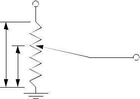
13.4.1 Potentiometers
•A variable resistor is used to convert a displacement to resistance/voltage.
•These give absolute position readings.
•The basic principle of operation is that a moving wiper (sensor input) moves a contact along a resistor. The ends of the resistor are connected to reference voltages. As the wiper moves the potentiometer acts as a voltage divider and produces a voltage proportional to position.
V
Vout=V(a/L)
L
a
13.4.2 Linear Variable Differential Transformers (LVDT)
•This is effectively a transformer with a moving inner core. The moving core changes the inductance, and this can be converted to a position.
•In these devices there are three sets of windings. The first set of windings is in the center, and is powered by an AC source. The other two coils are at the opposite sides of the main coils. As the core is moved forward/back the magnetic coupling will change.
page 171
A rod drives the sliding core
AC input |
Signal Out
•If the core shown is in the center, the output will be 0Vac, as it shifts to the left there will be more coupling between the center and left coil, and the signal magnitude will be larger than the right hand coil. This difference can be converted to a calculated difference.
•This sensor is used for linear position sensing to high accuracies such as,
-load cells
-bourdon tubes
-dimensional measurement for SPC
-bellows/diaphragm
•The signals from theLVDT can be conditioned with the circuit below.
|
|
|
|
|
|
|
|
|
|
|
|
Vac out |
|
|
Vdc out |
||
|
|
||||
Vac in |
LVDT |
page 172
• Near the center of the movement range the voltage is linearly proportional to core movement.
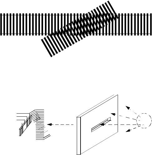
13.4.3 Moire Fringes
•By overlapping two fine lines patterns we can measure displacement.
1.The Pattern - two sheets with thin fringes are put at right angles, the optical effect is a darkened strip that runs along the strips. As one of the strips is moved the band will move up or down. When optically magnified the moving strip can be used to determine direction, and distance of motion.
2.The Detector - a collimated light source is shone upon the pattern. The light is then reflected back to a grid of sensors. The sensors then go on/off to indicate the presence of the band.
on off on off 

• These are used in high precision applications, and are not available as off the shelf sensors.