

6.Experiments
.pdf2.3. A VERY SIMPLE CIRCUIT |
33 |
Here there is no "shorting" wire present on the breadboard, yet there is a short circuit, and the lamp refuses to light. Based on your understanding of breadboard hole connections, can you determine where the "short" is in this circuit?
Short circuits are generally to be avoided, as they result in very high rates of electron °ow, causing wires to heat up and battery power sources to deplete. If the power source is substantial enough, a short circuit may cause heat of explosive proportions to manifest, causing equipment damage and hazard to nearby personnel. This is what happens when a tree limb "shorts" across wires on a power line: the limb { being composed of wet wood { acts as a low-resistance path to electric current, resulting in heat and sparks.
You may also build the battery/lamp circuit on a terminal strip: a length of insulating material with metal bars and screws to attach wires and component terminals to. Here is an example of how this circuit might be constructed on a terminal strip:
-
+
Terminal
strip

34 |
CHAPTER 2. BASIC CONCEPTS AND TEST EQUIPMENT |
2.4Ammeter usage
PARTS AND MATERIALS
²6-volt battery
²6-volt incandescent lamp
Basic circuit construction components such as breadboard, terminal strip, and jumper wires are also assumed to be available from now on, leaving only components and materials unique to the project listed under "Parts and Materials."
CROSS-REFERENCES
Lessons In Electric Circuits, Volume 1, chapter 1: "Basic Concepts of Electricity" Lessons In Electric Circuits, Volume 1, chapter 8: "DC Metering Circuits"
LEARNING OBJECTIVES
²How to measure current with a multimeter
²How to check a multimeter's internal fuse
²Selection of proper meter range
SCHEMATIC DIAGRAM
|
Ammeter |
|
A |
Battery |
Lamp |
ILLUSTRATION

2.4. AMMETER USAGE |
35 |
|
|
|
|
|
|
|
|
|
|


 V
V 


 A
A


 V
V 


 A
A
OFF
A COM
-
+

 Lamp
Lamp
Battery
INSTRUCTIONS
Current is the measure of the rate of electron "°ow" in a circuit. It is measured in the unit of the Ampere, simply called "Amp," (A).
The most common way to measure current in a circuit is to break the circuit open and insert an "ammeter" in series (in-line) with the circuit so that all electrons °owing through the circuit also have to go through the meter. Because measuring current in this manner requires the meter be made part of the circuit, it is a more di±cult type of measurement to make than either voltage or resistance.
Some digital meters, like the unit shown in the illustration, have a separate jack to insert the red test lead plug when measuring current. Other meters, like most inexpensive analog meters, use the same jacks for measuring voltage, resistance, and current. Consult your owner's manual on the particular model of meter you own for details on measuring current.
When an ammeter is placed in series with a circuit, it ideally drops no voltage as current goes through it. In other words, it acts very much like a piece of wire, with very little resistance from one test probe to the other. Consequently, an ammeter will act as a short circuit if placed in parallel (across the terminals of) a substantial source of voltage. If this is done, a surge in current will result, potentially damaging the meter:

36 |
CHAPTER 2. BASIC CONCEPTS AND TEST EQUIPMENT |
||
|
|
|
|
|
|
|
|
|
|
|
|


 V
V 


 A
A


 V
V 


 A
A
OFF
A COM
current  surge
surge
 - +
- +
SHORT CIRCUIT !
Battery
current surge
Ammeters are generally protected from excessive current by means of a small fuse located inside the meter housing. If the ammeter is accidently connected across a substantial voltage source, the resultant surge in current will "blow" the fuse and render the meter incapable of measuring current until the fuse is replaced. Be very careful to avoid this scenario!
You may test the condition of a multimeter's fuse by switching it to the resistance mode and measuring continuity through the test leads (and through the fuse). On a meter where the same test lead jacks are used for both resistance and current measurement, simply leave the test lead plugs where they are and touch the two probes together. On a meter where di®erent jacks are used, this is how you insert the test lead plugs to check the fuse:

2.4. AMMETER USAGE |
37 |
Low resistance  indication = good fuse
High resistance |
V |
A |
|
indication = "blown" fuse |
|||
|
|


 V
V 


 A
A
OFF
A COM
Internal location of fuse
touch probes together
Build the one-battery, one-lamp circuit using jumper wires to connect the battery to the lamp, and verify that the lamp lights up before connecting the meter in series with it. Then, break the circuit open at any point and connect the meter's test probes to the two points of the break to measure current. As usual, if your meter is manually-ranged, begin by selecting the highest range for current, then move the selector switch to lower range positions until the strongest indication is obtained on the meter display without over-ranging it. If the meter indication is "backwards," (left motion on analog needle, or negative reading on a digital display), then reverse the test probe connections and try again. When the ammeter indicates a normal reading (not "backwards"), electrons are entering the black test lead and exiting the red. This is how you determine direction of current using a meter.
For a 6-volt battery and a small lamp, the circuit current will be in the range of thousandths of an amp, or milliamps. Digital meters often show a small letter "m" in the right-hand side of the display to indicate this metric pre¯x.
Try breaking the circuit at some other point and inserting the meter there instead. What do you notice about the amount of current measured? Why do you think this is?
Re-construct the circuit on a breadboard like this:

38 |
CHAPTER 2. BASIC CONCEPTS AND TEST EQUIPMENT |
-
+
Breadboard
Students often get confused when connecting an ammeter to a breadboard circuit. How can the meter be connected so as to intercept all the circuit's current and not create a short circuit? One easy method that guarantees success is this:
²Identify what wire or component terminal you wish to measure current through.
²Pull that wire or terminal out of the breadboard hole. Leave it hanging in mid-air.
²Insert a spare piece of wire into the hole you just pulled the other wire or terminal out of. Leave the other end of this wire hanging in mid-air.
²Connect the ammeter between the two unconnected wire ends (the two that were hanging in mid-air). You are now assured of measuring current through the wire or terminal initially identi¯ed.

2.4. AMMETER USAGE |
39 |
|
|
|
|
|
|
m |
wire pulled |
V |
A |
|
|
|
out of |
|
|
breadboard |
V |
A |
|
|
OFF |
- |
|
|
+ |
A |
COM |
|
spare wire
Again, measure current through di®erent wires in this circuit, following the same connection procedure outlined above. What do you notice about these current measurements? The results in the breadboard circuit should be the same as the results in the free-form (no breadboard) circuit.
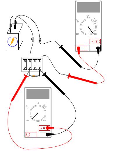
Building the same circuit on a terminal strip should also yield similar results:

40 |
CHAPTER 2. BASIC CONCEPTS AND TEST EQUIPMENT |
||
|
|
|
|
|
|
m |
|
|
V |
A |
|
+ |
- |
|
|
V |
A |
||
|
|||
|
|
OFF |
|
|
A |
COM |
Terminal
strip
The current ¯gure of 24.70 milliamps (24.70 mA) shown in the illustrations is an arbitrary quantity, reasonable for a small incandescent lamp. If the current for your circuit is a di®erent value, that is okay, so long as the lamp is functioning when the meter is connected. If the lamp refuses to light when the meter is connected to the circuit, and the meter registers a much greater reading, you probably have a short-circuit condition through the meter. If your lamp refuses to light when the meter is connected in the circuit, and the meter registers zero current, you've probably blown the fuse inside the meter. Check the condition of your meter's fuse as described previously in this section and replace the fuse if necessary.

2.5. OHM'S LAW |
41 |
2.5Ohm's Law
PARTS AND MATERIALS
²Calculator (or pencil and paper for doing arithmetic)
²6-volt battery
²Assortment of resistors between 1 K- and 100 k- in value
I'm purposely restricting the resistance values between 1 k- and 100 k- for the sake of obtaining accurate voltage and current readings with your meter. With very low resistance values, the internal resistance of the ammeter has a signi¯cant impact on measurement accuracy. Very high resistance values can cause problems for voltage measurement, the internal resistance of the voltmeter substantially changing circuit resistance when it is connected in parallel with a high-value resistor.
At the recommended resistance values, there will still be a small amount of measurement error due to the "impact" of the meter, but not enough to cause serious disagreement with calculated values.
CROSS-REFERENCES
Lessons In Electric Circuits, Volume 1, chapter 2: "Ohm's Law"
LEARNING OBJECTIVES
²Voltmeter use
²Ammeter use
²Ohmmeter use
²Use of Ohm's Law
SCHEMATIC DIAGRAM |
|
|
|
Ammeter |
|
|
A |
|
Battery |
Resistor |
V Voltmeter |
ILLUSTRATION
42 |
CHAPTER 2. BASIC CONCEPTS AND TEST EQUIPMENT |
||
|
|
|
|
|
Ammeter |
|
|
|
V |
A |
|
+ |
- |
|
|
V |
A |
||
|
|||
|
|
OFF |
|
|
A |
COM |
Terminal
strip
Resistor
V |
A Voltmeter |
V |
A |
|
OFF |
A |
COM |
INSTRUCTIONS
Select a resistor from the assortment, and measure its resistance with your multimeter set to the appropriate resistance range. Be sure not to hold the resistor terminals when measuring resistance, or else your hand-to-hand body resistance will in°uence the measurement! Record this resistance value for future use.
Build a one-battery, one-resistor circuit. A terminal strip is shown in the illustration, but any form of circuit construction is okay. Set your multimeter to the appropriate voltage range and measure voltage across the resistor as it is being powered by the battery. Record this voltage value along with the resistance value previously measured.
Set your multimeter to the highest current range available. Break the circuit and connect the ammeter within that break, so it becomes a part of the circuit, in series with the battery and resistor. Select the best current range: whichever one gives the strongest meter indication without