

6.Experiments
.pdf2.2. OHMMETER USAGE |
23 |
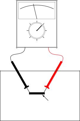
No continuity
Analog
meter
- 
 +
+
22-gauge wire |
22-gauge wire |
|
|
|
|
|
|
|
|
|
|
|
|
|
Breadboard
An important concept in electricity, closely related to electrical continuity, is that of points being electrically common to each other. Electrically common points are points of contact on a device or in a circuit that have negligible (extremely small) resistance between them. We could say, then, that points within a breadboard column (vertical in the illustrations) are electrically common to each other, because there is electrical continuity between them. Conversely, breadboard points within a row (horizontal in the illustrations) are not electrically common, because there is no continuity between them. Continuity describes what is between points of contact, while commonality describes how the points themselves relate to each other.
Like continuity, commonality is a qualitative assessment, based on a relative comparison of resistance between other points in a circuit. It is an important concept to grasp, because there are certain facts regarding voltage in relation to electrically common points that are valuable in circuit analysis and troubleshooting, the ¯rst one being that there will never be substantial voltage dropped between points that are electrically common to each other.
Select a 10,000 ohm (10 k-) resistor from your parts assortment. This resistance value is indicated by a series of color bands: Brown, Black, Orange, and then another color representing the precision of the resistor, Gold (+/- 5%) or Silver (+/- 10%). Some resistors have no color for precision, which marks them as +/- 20%. Other resistors use ¯ve color bands to denote their value and precision, in which case the colors for a 10 k- resistor will be Brown, Black, Black, Red, and a ¯fth color for

24 |
CHAPTER 2. BASIC CONCEPTS AND TEST EQUIPMENT |
precision.
Connect the meter's test probes across the resistor as such, and note its indication on the resistance scale:
Analog
meter
Resistor
- 
 +
+
If the needle points very close to zero, you need to select a lower resistance range on the meter, just as you needed to select an appropriate voltage range when reading the voltage of a battery.
If you are using a digital multimeter, you should see a numerical ¯gure close to 10 shown on the display, with a small "k" symbol on the right-hand side denoting the metric pre¯x for "kilo" (thousand). Some digital meters are manually-ranged, and require appropriate range selection just as the analog meter. If yours is like this, experiment with di®erent range switch positions and see which one gives you the best indication.
Try reversing the test probe connections on the resistor. Does this change the meter's indication at all? What does this tell us about the resistance of a resistor? What happens when you only touch one probe to the resistor? What does this tell us about the nature of resistance, and how it is measured? How does this compare with voltage measurement, and what happened when we tried to measure battery voltage by touching only one probe to the battery?
When you touch the meter probes to the resistor terminals, try not to touch both probe tips to your ¯ngers. If you do, you will be measuring the parallel combination of the resistor and your own body, which will tend to make the meter indication lower than it should be! When measuring a 10 k- resistor, this error will be minimal, but it may be more severe when measuring other values of resistor.
You may safely measure the resistance of your own body by holding one probe tip with the ¯ngers of one hand, and the other probe tip with the ¯ngers of the other hand. Note: be very careful with the probes, as they are often sharpened to a needle-point. Hold the probe tips along their length, not at the very points! You may need to adjust the meter range again after measuring the 10 k- resistor, as your body resistance tends to be greater than 10,000 ohms hand-to-hand. Try wetting your ¯ngers with water and re-measuring resistance with the meter. What impact does this
2.2. OHMMETER USAGE |
25 |
have on the indication? Try wetting your ¯ngers with saltwater prepared using the glass of water and table salt, and re-measuring resistance. What impact does this have on your body's resistance as measured by the meter?
Resistance is the measure of friction to electron °ow through an object. The less resistance there is between two points, the harder it is for electrons to move (°ow) between those two points. Given that electric shock is caused by a large °ow of electrons through a person's body, and increased body resistance acts as a safeguard by making it more di±cult for electrons to °ow through us, what can we ascertain about electrical safety from the resistance readings obtained with wet ¯ngers? Does water increase or decrease shock hazard to people?
Measure the resistance of a rectifying diode with an analog meter. Try reversing the test probe connections to the diode and re-measure resistance. What strikes you as being remarkable about the diode, especially in contrast to the resistor?
Take a piece of paper and draw a very heavy black mark on it with a pencil (not a pen!). Measure resistance on the black strip with your meter, placing the probe tips at each end of the mark like this:
- 
 +
+
Mark made with pencil
Paper
Move the probe tips closer together on the black mark and note the change in resistance value. Does it increase or decrease with decreased probe spacing? If the results are inconsistent, you need to redraw the mark with more and heavier pencil strokes, so that it is consistent in its density. What does this teach you about resistance versus length of a conductive material?

26 |
CHAPTER 2. BASIC CONCEPTS AND TEST EQUIPMENT |
Connect your meter to the terminals of a cadmium-sulphide (CdS) photocell and measure the change in resistance created by di®erences in light exposure. Just as with the light-emitting diode (LED) of the voltmeter experiment, you may want to use alligator-clip jumper wires to make connection with the component, leaving your hands free to hold the photocell to a light source and/or change meter ranges:
Light source
Photocell 

- 
 +
+
Experiment with measuring the resistance of several di®erent types of materials, just be sure not to try measure anything that produces substantial voltage, like a battery. Suggestions for materials to measure are: fabric, plastic, wood, metal, clean water, dirty water, salt water, glass, diamond (on a diamond ring or other piece of jewelry), paper, rubber, and oil.

2.3. A VERY SIMPLE CIRCUIT |
27 |
2.3A very simple circuit
PARTS AND MATERIALS
²6-volt battery
²6-volt incandescent lamp
²Jumper wires
²Breadboard
²Terminal strip
From this experiment on, a multimeter is assumed to be necessary and will not be included in the required list of parts and materials. In all subsequent illustrations, a digital multimeter will be shown instead of an analog meter unless there is some particular reason to use an analog meter. You are encouraged to use both types of meters to gain familiarity with the operation of each in these experiments.
CROSS-REFERENCES
Lessons In Electric Circuits, Volume 1, chapter 1: "Basic Concepts of Electricity"
LEARNING OBJECTIVES
²Essential con¯guration needed to make a circuit
²Normal voltage drops in an operating circuit
²Importance of continuity to a circuit
²Working de¯nitions of "open" and "short" circuits
²Breadboard usage
²Terminal strip usage
SCHEMATIC DIAGRAM
Battery |
Lamp |
ILLUSTRATION |
|

28 |
CHAPTER 2. BASIC CONCEPTS AND TEST EQUIPMENT |
-
+

 Lamp
Lamp
Battery
INSTRUCTIONS
This is the simplest complete circuit in this collection of experiments: a battery and an incandescent lamp. Connect the lamp to the battery as shown in the illustration, and the lamp should light, assuming the battery and lamp are both in good condition and they are matched to one another in terms of voltage.
If there is a "break" (discontinuity) anywhere in the circuit, the lamp will fail to light. It does not matter where such a break occurs! Many students assume that because electrons leave the negative (-) side of the battery and continue through the circuit to the positive (+) side, that the wire connecting the negative terminal of the battery to the lamp is more important to circuit operation than the other wire providing a return path for electrons back to the battery. This is not true!
+ |
- |
No light! |
|
||
|
|
Lamp
Battery
break in circuit
|
- |
break in circuit |
|
+ |
No light! |
||
|
|||
|
|
Lamp
Battery

2.3. A VERY SIMPLE CIRCUIT
break in circuit
-
+
Battery
break in circuit
-
+
Battery
29
No light!
Lamp
No light!
Lamp
Using your multimeter set to the appropriate "DC volt" range, measure voltage across the battery, across the lamp, and across each jumper wire. Familiarize yourself with the normal voltages in a functioning circuit.
Now, "break" the circuit at one point and re-measure voltage between the same sets of points, additionally measuring voltage across the break like this:

30 |
|
CHAPTER 2. BASIC CONCEPTS AND TEST EQUIPMENT |
|
|
|
|
|
|
|
|
|


 V
V 


 A
A


 V
V 


 A
A
OFF
A COM
+ |
- |
No light! |
|
||
|
|
|
Battery |
|
Lamp |
|
|
What voltages measure the same as before? What voltages are di®erent since introducing the break? How much voltage is manifest, or dropped across the break? What is the polarity of the voltage drop across the break, as indicated by the meter?
Re-connect the jumper wire to the lamp, and break the circuit in another place. Measure all voltage "drops" again, familiarizing yourself with the voltages of an "open" circuit.
Construct the same circuit on a breadboard, taking care to place the lamp and wires into the breadboard in such a way that continuity will be maintained. The example shown here is only that: an example, not the only way to build a circuit on a breadboard:

2.3. A VERY SIMPLE CIRCUIT |
31 |
-
+
Breadboard
Experiment with di®erent con¯gurations on the breadboard, plugging the lamp into di®erent holes. If you encounter a situation where the lamp refuses to light up and the connecting wires are getting warm, you probably have a situation known as a short circuit, where a lower-resistance path than the lamp bypasses current around the lamp, preventing enough voltage from being dropped across the lamp to light it up. Here is an example of a short circuit made on a breadboard:

32 |
CHAPTER 2. BASIC CONCEPTS AND TEST EQUIPMENT |
-
+
No light!
"shorting" wire
Breadboard
Here is an example of an accidental short circuit of the type typically made by students unfamiliar with breadboard usage:
-
+
No light!
Breadboard