

3 Semester
1 Module electrical protection devices Air Circuit Breakers for Alternators
A majority of circuit breakers used onboard ships are air circuit breakers rather than oil-immersed or vacuum-break types which are common ashore. Figure 11.6 (a) depicts a typical air circuit breaker’s construction while figure 11.6 (b) is a pictorial diagram. It comprises of fixed contacts, arranged in such a manner that the arching contacts make before and break after the main contacts. The main contacts are usually silver-faced copper, copper with silver inserts or silver-cadmium oxide and the arching contacts are usually silver-tungsten or silver-cadmium oxide. These combine to provide minimum contact resistance and carry current with reduced crosion.
If severe burning or pitting occurs on the main contacts, they need to be filed. The manufacturer's handbook will give instructions to rectify this. It is often caused by misalignment of the contacts.
The arcing contacts are normally subject to burning and can be dressed with a smooth file, but not emery cloth. The abrasive particles from the emery cloth may get dislodged and embed themselves in the smooth silvered surfaces of the contacts. Circuit breakers are capable of breaking under the influence of very large short-circuit currents. This is achieved by providing a fast break with long travel to hinder arc formation. Sometimes silver-coated roller-contacts are used to achieve this. Arc extinction occurs as the arc rises into the splitter (arc chute). Never allow a circuit breaker to operate with the arc chutes removed.
Sometimes, blow-out coils, which are connected in series with the circuit breaker contacts, form an electro-magnetic field which reacts with the arc to give a deflecting force that tends to blow the arc upwards and thus outwards. The increase in effective length of the arc causes it to extinguish more quickly. The blow out coil is protected from the arc by are resistant material which may be in the form of an air chute.
Hot ionized gases around the arc and contacts are displaced by cold air thereby forming an eddy current air flow. This helps to increase the resistance between contacts. Contact design and other innovations have rendered blow out coils obsolete but they may still be found.
The air-break circuit breakers used for marine installations are frame-mounted and arranged for isolation from the bus bars and alternator input cable contacts by being moved horizontally forward to a fixed position. The isolating plugs are not designed for making or breaking contact on load and so the breaker must be open before the assembly is withdrawn.
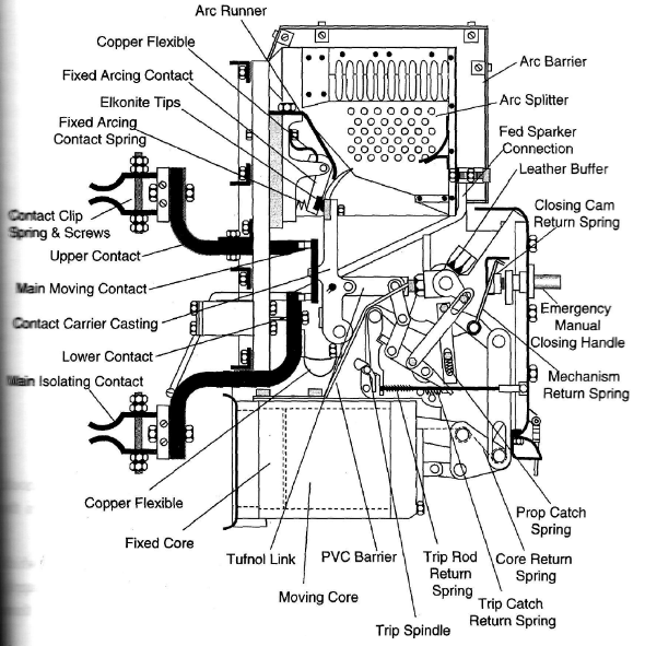
Figure 11.6(a) - Sectional View of an Air Circuit Breaker
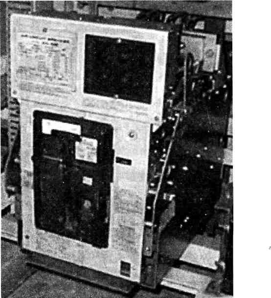
Figure 11.6(b) - Pictorial Diagram of an Air Circuit Breaker
Figure 11.7 is nothing but a simplified diagram of Figure 11.6(a). Safety interlocks should be fitted to ensure that the circuit breaker assembly cannot be racked out or in when the contacts are closed. The interlocks are usually mechanical in nature.
Maintenance is facilitated by the draw-out compartments and extending guide rails which allow the breaker to be pulled out completely. The alternator breaker for three-phase supply has a single unit for each phase, of similar design to the example in Figure 11.7. The three units are linked together by an insulated bar for simultaneous operation.
Main fixed and moving contacts are made of high-conductivity copper and as an aid to low contact resistance, the faces are silver-plated. Main contacts are designed to carry normal full load current without overheating and overload current until tripped, when a fault occurs.
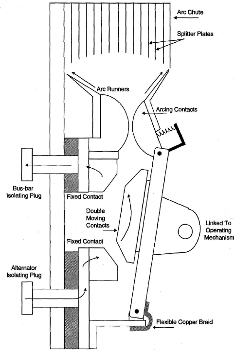
Figure 11.7 - Air-break Circuit Breaker (ACB) for Alternators
Interruption of current flow results in the production of an arc between contact faces. Arcing is severe with overload current but is not a serious problem during normal operation. As mentioned earlier, in order to prevent damage to main contacts, separate arcing supplementary contacts are used. These are made of arc-resisting alloy such as silver tungsten and easily replaced if damaged. They should be inspected after a faulty operation of the breaker. The arcing contact shown, has a spring which pushes it forward so as to hold it in the closed position until after the main contacts have opened.
Air-break circuit breakers with arcing contacts have always been used for d.c. switchboards but further development was necessary to improve arc control before such breakers could replace oil circuit breakers and be used for a.c. Later development has meant that they can be used on systems with voltages up to 3.3kV.
Arc control requires that the arc be elongated and removed from the gap between the arcing contacts. Electromagnetic forces associated with the arc and thermal action will cause it to move up the arc runners to the arc chute, which is provided for the purpose. Thus the arc is elongated and finally chopped into sections and also cooled with the help of the splitter plates in the chute.
Arc chutes are made of insulated arc-resisting material. They confine the arc and produce a funnel effect, which assists thermal action. Splitter plates are made of metal (steel or copper) in some breakers, and in others, made of insulator material. Some breakers have horizontal rods fitted to cool and split the arc. Arc runners are fixed and not of the moving type as in some designs. Interruption of the arc is assisted by the current dropping to zero during the cycle. However, with three phases the zero points in each phase are staggered Contact opening is therefore followed by the current falling to zero and this means that for the next part of the cycle an arc has to be struck across a gap.
Successful removal of ionized gas (from the arc, a result of the contact opening) will increase the resistance in the air gap between the contacts. When gas remains, it provides a path across which the arc can re-strike. The rate at which the gas is removed is such that the arc will not re-strike more than two or three times.
Breaking speed is made as high as possible by powerful throw-off springs and light construction of the moving arm assembly. Anti-bounce devices prevent any rebound at the end of the opening movement.
Rapid closing of the breaker also helps to prevent damage and most are power, neither than manually, closed. Power is provided by a solenoid or by a spring, which is automatically rewound (re-charged) by a motor and left ready after each closing operation. Where springs are used, an emergency hand-tensioning method is arranged for use with a dead switchboard, so that the spring can be wound up and made ready for closing the breaker.
After operation of a spring-activated breaker, the motor can usually be heard charging the spring for the next time. Feeder and distribution circuits are usually protected by the moulded-case type or the miniature type of circuit breakers.
Moulded Case Circuit Breakers (MCCBs)
These are small, compact air circuit breakers fitted in a moulded plastic case. They have a lower current rating than ACBs (30-1500A) and generally a lower breaking capacity. Figure 11.8 (a) is a pictorial representation of various MCCBs and Figure 11.8(b) depicts a sectional view of the same.
Figure 11.8(a) - Moulded
Case Circuit Breakers
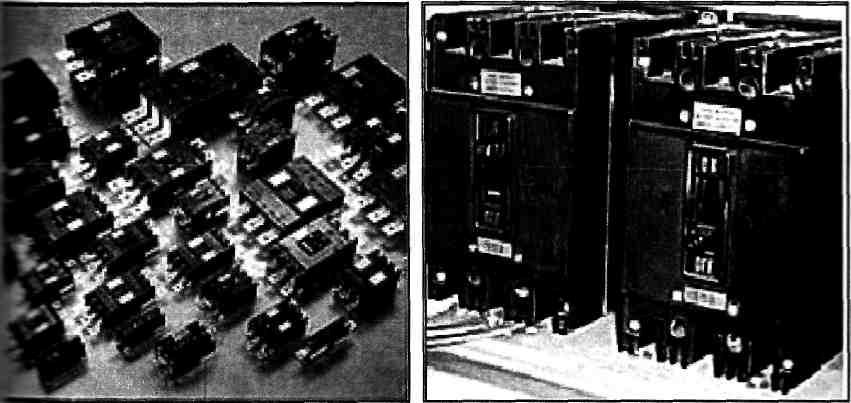
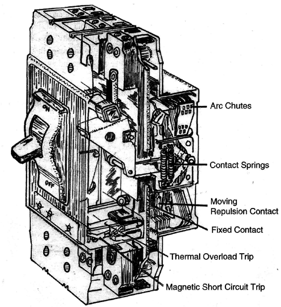
Figure 11.8(b) - Sectional View of a Moulded Case Circuit Breaker
MCCBs usually have an adjustable thermal overload setting and an adjustable or fixed magnetic over-current trip for short-circuit protection built into the case. An under voltage; trip coil may also be included within the case.
A hand-operated lever usually closes MCCBs but a motor closing arrangement can also the incorporated. MCCBs are claimed to be reliable, trouble free and require negligible maintenance. If the breaker remains 'On' for long periods, it should be tripped and closed a few times in order to free the mechanism and clean the contacts. Terminals should be checked for tightness otherwise damage due to overheating would occur. The front cover of larger MCCBs (around 400A rating) can usually be removed, interior dust blown out and the contracts dressed with a file if required.
Following tripping after a short-circuit fault, the breaker should be inspected for damage, checked for correct operation, and its insulation resistance measured. A reading of at least 4 to IO is usually required. Any other faulty operation usually requires replacement or overhaul by the manufacturer. MCCBs can be used for every application on board a ship – from generator breakers to small distribution breakers. The limited breaking capacity may demand that a 'back-up' fuse be fitted for very high prospective short-circuit fault levels. Some applications are mentioned in the paragraphs that follow:
Feeder Protection
They are ideally suited for outgoing feeder circuits on distribution boards. The selected MCCB should have adequate interrupting capacity and the MCCB current rating should be equal to that of the load.
Capacitor Control
They are suitable for controlling LT capacitors for power factor correction. To avoid clipping while switching on the capacitors, the MCCB rating should be around 1.5 - 2 times the rated current of the capacitors so as to cater to initial inrush currents.
Diesel-Generator Set Protection
They can be used for effective protection and control of diesel-generating sets (against overloads and short circuits).
Hoist I Elevator I Crane Control
They can withstand continuous vibrations of 2g and shocks up to 15g without affecting their performance. As such they offer the best protection for hoist / elevator / crane applications.
Furnace Control
These are suitable for high frequency systems up to 400 Hz. Hence they can be ideally used for control of high frequency furnaces. A de-rating factor of 0.8 is to be employed for arriving at the rated current of the MCCB. However it must be noted that fully magnetic MCCBs are not suitable for this application.
DC Power Supply Control
Rectifier panels which act as a source of d.c. supply can be conveniently protected by MCCBs. Moreover, MCCBs being suitable for both - a.c. as well as d.c. systems, control and protection of input as well as output sides of the rectifier is also possible.
Miscellaneous Marine Applications
They are ideally suitable for a variety of marine applications. These have cleared the most stringent performance, durability and environmental tests. While the durability tests include a, Vibration Test at 10g, Bump Test at 40g and Shock Test at 70g, the environmental test include the Damp Heat (steady state) Test, Damp Heat (cyclic) Test, Mould Growth Test and the Corrosive Atmosphere (salt spray) Test.
Miniature Circuit Breakers (MCBs)
MCBs are very small air circuit breakers also fitted in moulded plastic cases. They have current ratings of 5-100A and generally thermal overload and magnetic short-circuit protection. They have a very limited breaking capacity (300A) and are commonly used in final distribution boards (DBs) instead of fuses. The distribution board is supplied via a fuse or MCCB with the required breaking capacity. (Refer Figure 11.9).
Advantages
They are set to a pre-determined rating at the factory
It is easy to check if the breaker has tripped or not
The supply to the circuit is easily reinstated
Multi-pole units are available
They can discriminate between sustained and transient loads.
Disadvantages
They are costly
They have mechanical moving parts
Tripping heavy overloads causes distortion due to heat
Ambient temperature affects their characteristics
Regular tests are required to ensure their satisfactory operation
MCBs must be replaced if faults develop. No maintenance is generally possible
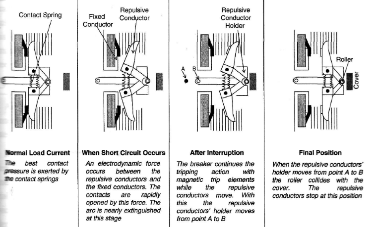
Figure 11.9 - A Miniature Circuit Breaker (MCB) operating during a Short-circuit
Residual Current Circuit Breakers (RCCBs)
Residual current operated circuit breakers are widely used now to provide shock protection from leakage currents. They are also known as Earth Leakage Circuit Breakers. "ELCB" is the common abbreviation for leakage protection devices of both voltage-operated and current-operated types. These are now mandatory for voltage installations up to 5kW. The common MCBs, fuses, etc., are not designed for protection against leakage currents, which can cause shocks or even trigger a fire.
Effective use of RCCBs involves good wiring and earthing. Generally a 30mA RCCB with an operating time of 4 milliseconds is recommended for life safety and 100mA or 300mA ones for fire protection. They are also found in the range of 40 -50mA. Leakage currents in the range of a few hundred milliamperes might lead to insulation failures and result in fires (Refer Figure 11.10).
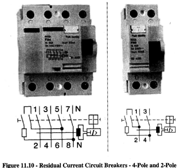
In the United States these are called GFCIs (Ground Fault Current Interrupters) and breakers with barely 5mA sensitivity are recommended for personnel protection. In some countries, only breakers with 30, 100 and 300 mA are available with a tripping time of 30 to 40 ms and are generally accepted in domestic and industrial circles. Few manufacturers offer MCBs and RCCBs rolled into one unit with a delay tripping time of up to 200 ms. The increased delay enhances discrimination from nuisance tripping. These are now called RCBOs (Residual Current Circuit Breaker with Over-current Protection). The following specifications are furnished from one manufacturer.
Application and Scope of the Residual Current Circuit Breaker
This is in conformity with the standards of IEC1008, GB16916, VDE 0664 and BS 4293. It can cut off the fault circuit immediately in the event of a shock hazard or earth leakage of a line. Thus it is suitable to avoid the shock hazard and fire caused by any earth leakage. This is mainly suitable for use in a variety of plants and enterprises, buildings, constructions, commercial areas, guesthouses and family dwellings. It can be used in single phase 220Vand three phase 380V 50 to 60 Hz circuits. It is not suitable for use in a d.c. pulse system.
Alternator and Associated Systems' Protection
Protective devices are built into main alternator breakers to safeguard both the individual alternator and the distribution system against certain faults. Over-current protection is achieved by means of relays which cut power supplies to non-essential services on a preferential basis, as well as breaker overload current trips and instantaneous short-circuit current tripping. A reverse power trip is fitted where alternators are intended for parallel operation (in some vessels they are not), unless equivalent protection is provided by other means. Parallel operation of alternators also requires an under-voltage release for the breaker.
Over-current Protection
Various methods are used to detect over-current in a circuit. They have an inverse current-time characteristic, i.e. the higher the current, the faster will it operate. A few of these:
Magnetic
The solenoid drives an iron core to operate a 'trip' switch. The core movement is 'slugged' by either an oil dashpot or a mechanical delay (clockwork action).
Thermal
A thermal relay utilizes the bending action (or rather the coefficient of expansion) of a bimetallic bar to trip the circuit breaker. The time taken to heat the bimetal gives the necessary time lag. Thermal relays are commonly fitted in moulded case circuit breakers (MCCBs) and in miniature circuit breakers (MCBs) for overload protection.
Electronic
An electronic over-current relay usually converts the current into a proportional voltage. This is then compared with a set voltage level within the transistorized monitoring unit. The time delay is obtained by the time taken to charge a capacitor. This type of relay usually has separate adjustments for current trip level and for trip time. The amplifiers within the electronic relay require a power supply (usually 110, 220 or 440V a.c).
Both the magnetic and electronic relays can be set to give an almost instantaneous trip (typically 0.05 sec.) to clear a short-circuit fault.
Over current protection current transformers (CTs) generally drive relays. The CT secondary usually has a 5A or 1A rating for full load current in its primary winding. Injecting test currents to check their current trip levels and time lags can help to test all over-current relays.
Primary injection is where current is fed through the normal load circuit. This requires a large injection test set. The test set is essentially a transformer and controller rather like a welding set, i.e. it gives a low voltage - high current output.
Secondary injection feeds current directly into the over-current relay. This requires only a small current (5 - 10A). Secondary injection does not prove the CT performance but is like a most common, reliable method for testing an over-current relay.
The setting up of an over-current relay is obviously critical to its protective duty. It is carried out in strict accordance with the manufacturer's instructions. Such setting up is done during acceptance trials of a new ship and at subsequent periodic surveys.
The alternator breaker has an over-current trip, but a major consideration is that the supply of power to the switchboard must be maintained if possible. The breaker is therefore designed to be tripped instantly only in the event of high over-current such as that associated with a short-circuit fault. When over current is not so high, a delay with an inverse time characteristic allows an interval before the breaker is opened. During this time the overload fault may be cleared.
Overload of an alternator may be due to an increased switchboard load or due to a serious fault, causing high current flow. Straightforward overload (apart from the brief overload due to the starting currents of motors) is reduced by the preference trips which are designed to shed non-essential switchboard load. Preference trips may be operated by relays set at about 110% of the normal full load. They open the breakers feeding ventilation fans, air conditioning equipment, etc. The non-essential systems are disconnected at timed intervals, hence reducing alternator load. A serious fault on the distribution side of the switchboard should cause the appropriate supply breaker to open, or fuse to operate due to over-current. Disconnection of faulty equipment will reduce alternator overload.