

Fundamental Concepts
Steering Gear
Elementary steering gear first of all comprises a steering wheel (or maybe a control knob) on the bridge, generally operated by the helmsman. The helm order or desired angle of the rudder is then transmitted from here to the steering control unit. This results in ac operation of the rudder to which it is linked. A negative feedback signal of this ordered (or desired) angle is transmitted automatically through 'hunting gear' to the steering gear’s control unit.
This (the negative feedback) gradually nullifies the control signal to the steering gear and causes the rudder to stop when the desired angle has been achieved. In the case of an electro-hydraulic system it is possible for the control unit to receive negative feedback signals through rotary transformers, potentiometers, etc. Now "helm angle" is the position of the steering wheel relative to the midship position. The steering control dials are normally graduated in such a manner that the rudder moves in tandem with it. For example, if the rudder is designed to move ±35°, then the control wheel will also have a fixed dial and pointer arrangement graduated from 0° to +35°.
In some steering gear systems, be it a wheel, knob or handle, the steering control element does not maintain a one-to-one relationship with the rudder. In such an instance, an independent rudder indicator is deemed necessary and will be in the form of the type mentioned in article 18.8.
Instead of just a fixed dial and pointer, a two-element synchro chain (i.e., a pair of transmitting and receiving synchros) may be used to indicate to the operator the position that is desired of the rudder. Article 18.9 explains the theory behind synchros. The indicator is also called a helm indicator. Classification rules now specify that an independent rudder angle indicator be fitted when the rudder is power operated.
Steering Gear Control
Steering gear control systems facilitate the control of the steering gear remotely from a steering console located in the pilothouse and locally from the steering gear space by means of a trick-wheel or any other acceptable arrangement like manual operation of hydraulic waives with the help of an operating handle. The control system may comprise the Autopilot/Follow-up type that has a console as shown in Figure 18.1 and/or the 'non-follow-up' type as depicted in Figure 18.2. Non-follow-up control units are also depicted in Figures 18.30 and 18.31.

In the non-follow-up mode, as long as a wheel / lever is held, or pushbutton is pressed. to energise the steering gear so that the rudder moves in one direction - either to port or starboard, the steering gear functions. It de-energises automatically at its mechanical limit -normally 30° to 35°. The rudder may also be moved a few degrees at a time, either to port or starboard, by deflecting the control (off 0°) for brief periods. The helmsman's keen sense of judgement is vital in order to ensure effective control of the rudder. Many a time, novices steer the vessel in a zigzag manner thereby wasting time and precious resources on board.
The second type of controller causes the rudder to automatically align amidships the moment the helmsman releases the controller. Refer article 18.3.2.2 titled Dual Non-Follow-up (Dual NFU) later in this chapter.
The third variant is the full follow-up system. It is also explained further on in this chapter. The modern version senses any existing error between the helm (the position of the rudder controller) and the rudder's true position with the help of a comparator. The error which is at essence an algebraic sum of the desired and true angles of the rudder is amplified and fed to the rudder control unit. This moves the rudder to the desired angle either port or starboard. As already mentioned, the rudder stops only when the negative feedback signal cancels out the desired angle signalled by the helm.
The rudder is held in position so long as the difference is equal to zero. The rudder will move once again when a difference arises by moving the helm or due to the drifting of the rudder on account of hydrodynamic forces.
Non -follow up steering (or time dependent steering)
The following explanation supports the Non-follow-up Control Diagram depicted in Figure 18.2. As briefly mentioned earlier, we will understand that while using the 'Non-follow-up' (NFU) system, the steering gear will function as long as the controller is held in an actuating position i.e., either to Port or Starboard, and will only stop when it moves back to an "Off or the central position or until the steering gear has reached its mechanical limit.
The control from the bridge is by means of a NFU lever or sometimes a wheel that is spring loaded. Since the rudder movement depends on the duration that the control is held off-centre, this variant of a steering control system is sometimes called 'time dependent steering'.
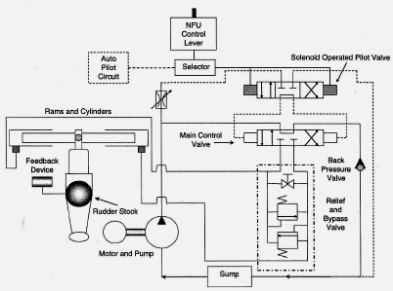
Figure 18.2 - Non-follow up Control Diagram of a Rudder
The NFU lever operates a switch that energises either a port or starboard solenoid, depending upon the direction of movement required. These solenoids in turn operate a pilot valve that brings about the operation of the main control valve.
As seen in Figure 18.2, the solenoid-operated pilot valve is a two-way-three-position one It is designed to divert hydraulic pressure through direct or cross-connected ports. A fixed delivery pump serves to deliver hydraulic pressure to the steering gear. Depending upon the application of pressure to a particular side or the ram, the desired direction of rudder movement is thus achieved. When the NFU lever is released, springs return it to the central position. This causes the control valve to return to its neutral position; the main control valve in turn also returns to neutral thus bypassing the pump delivery.
The steering gear stops for two reasons - first of all because there is no hydraulic pressure and secondly because, as we will see in Figure 18.2, the hydraulic fluid is trapped on either side of the ram due to the blind ports in the main control valve. The rudder indicator serves m a negative feed back device. It is capable of only serving as a visual feedback device. Thus the onus is on the helms-man to control the movement of the rudder. He is as an important link in the control chain and serves as a virtual hunting gear!