

ppl_05_e2
.pdfID: 3658
Customer: Oleg Ostapenko E-mail: ostapenko2002@yahoo.com
Customer: Oleg Ostapenko E-mail: ostapenko2002@yahoo.com
CHAPTER 4: MORE ABOUT AIRFLOW AND AEROFOILS QUESTIONS
6.As Indicated Air Speed (IAS) is reduced, in order to maintain altitude, the pilot must:
a.increase the angle of attack to maintain the correct lift force
b.decrease the angle of attack to reduce the drag
c.deploy the speed brakes to increase drag
d.reduce the thrust
7.Dynamic Pressure may be expressed by the formula:
a.Q = ½ ρ V²
b.Q = ρ V²
c.Q = ρ V
d.Q = 2 ρ V
8.The smooth fow of air, where each molecule follows the path of the preceding molecule, is a defnition of:
a.wind
b.turbulent fow
c.free-stream fow
d.laminar fow
9.If the cross sectional area of an airfow is mechanically reduced:
a.the mass fow remains constant and the static pressure increases
b.the velocity of the airfow remains constant and the mass fow increases
c.the mass fow remains constant and the velocity of the airfow increases
d.the velocity of the airfow remains constant and the kinetic energy increases
10.Dynamic pressure is:
a.the pressure change caused by heating when a moving airfow is brought completely to rest
b.the pressure due to the mass of air pressing down on the air beneath
c.the amount by which the pressure rises at a point where a moving airfow is brought completely to rest
d.the total pressure at a point where a moving airfow is brought completely to rest
11.The dynamic pressure exerted by the air on an aircraft’s frontal surface is equal to:
a.air density times speed squared
b.half the air density times the true airspeed squared
c.half the true airspeed times the air density squared
d.half the air density times the indicated airspeed squared
87

Order: 6026
Customer: Oleg Ostapenko E-mail: ostapenko2002@yahoo.com
Customer: Oleg Ostapenko E-mail: ostapenko2002@yahoo.com
CHAPTER 4: MORE ABOUT AIRFLOW AND AEROFOILS QUESTIONS
12.The term angle of attack is defned as:
a.the angle between the relative airfow and the horizontal axis
b.the angle between the wing chord line and the relative airfow
c.the angle that determines the magnitude of the lift force
d.the angle between the wing and tailplane incidence
13.In sub-sonic airfow, as air passes through a venturi, the mass fow ______, the velocity ___________ and the static pressure _____________.
a. |
decreases then increases |
remains constant |
|
increases then decreases |
|
b. |
remains constant |
increases then decreases |
|
decreases then increases |
|
c. |
remains constant |
increases then decreases |
|
increases then decreases |
|
d. |
decreases then increases |
increases then decreases |
|
increases then decreases |
|
14.An aircraft carries out a given journey, on two separate days. On both days, the pilot fies at an indicated airspeed of 120 knots. On the frst day, the air density is greater than on the subsequent day. How will the forces of Lift and Drag acting on the aircraft compare on the two days?
a.On the frst day both Lift and Drag will be less than on the subsequent day
b.On the frst day the Lift will be greater and Drag will be less than on the subsequent day
c.On the frst day the Lift will be less and Drag will be greater than on the subsequent day
d.The forces of Lift and Drag acting on the aircraft will remain unchanged
Question |
1 |
2 |
3 |
4 |
5 |
6 |
7 |
8 |
9 |
10 |
11 |
12 |
|
|
|
|
|
|
|
|
|
|
|
|
|
|
|
Answer |
|
|
|
|
|
|
|
|
|
|
|
|
|
|
|
|
|
|
|
|
|
|
|
|
|
|
|
Question |
13 |
14 |
|
|
|
|
|
|
|
|
|
|
|
|
|
|
|
|
|
|
|
|
|
|
|
|
|
Answer |
|
|
|
|
|
|
|
|
|
|
|
|
|
The answers to these questions can be found at the end of this book.
88
ID: 3658
Customer: Oleg Ostapenko E-mail: ostapenko2002@yahoo.com Customer: Oleg Ostapenko E-mail: ostapenko2002@yahoo.com
CHAPTER 5
DRAG
89

Order: 6026
Customer: Oleg Ostapenko E-mail: ostapenko2002@yahoo.com
Customer: Oleg Ostapenko E-mail: ostapenko2002@yahoo.com
CHAPTER 5: DRAG
90

ID: 3658
Customer: Oleg Ostapenko E-mail: ostapenko2002@yahoo.com Customer: Oleg Ostapenko E-mail: ostapenko2002@yahoo.com
CHAPTER 5: DRAG
DRAG.
INTRODUCTION.
The concept of drag has been touched upon in the chapters dealing with lift and airfow. Here, we must develop that concept further.
A body moving through a viscous fuid such as air will, because it displaces the air, experience a resistance to its motion which is given the name drag.
The chapter on lift has already given you an insight into the fact that, as well as lift, a drag force is generated by a wing as it moves through the air. In fact, aerodynamic drag is an inevitable by-product of lift (See Figure 5.1).
Figure 5.1 Drag is an inevitable by-product of lift.
But it is not only the wings which generate drag. All other parts of an aircraft’s airframe, too, give rise to a drag force which acts parallel and opposite to the direction of fight.
The combined drag produced by the airframe is called total drag.
Total drag is divided into two main sub categories: parasite drag and induced drag.
Parasite drag is the drag which is generated as the air fows around the aircraft, by virtue of such things as the aircraft’s shape, speed (dynamic pressure), frontal area, and the texture and condition of the aircraft’s surface. You will sometimes hear parasite drag referred to as profle drag or zero-lift drag. Zero-lift drag is a good descriptive term for parasite drag because it emphasises that this type of drag is unconnected to lift.
Induced drag is the drag which is produced as a by-product of lift. Parasite drag will be present even if the aircraft is fying at an angle of attack at which the wings are producing no lift. When the wings are producing lift, some drag will be generated which is additional to the parasite drag. The additional, lift-dependent drag is called induced drag. You may often hear induced drag called lift-dependent drag.
Total drag is made up of parasite drag and induced drag.
91

Order: 6026
Customer: Oleg Ostapenko E-mail: ostapenko2002@yahoo.com
Customer: Oleg Ostapenko E-mail: ostapenko2002@yahoo.com
CHAPTER 5: DRAG
Drag can almost always be regarded as a disadvantage, though, in some aspects of aircraft control, especially the control by the pilot of his aircraft’s approach to land, the presence of drag is essential. This is fortunate, because aerodynamic drag is an inevitable product of lift. Nevertheless, in most phases of fight, when an aircraft is climbing, in the cruise, or gliding for range, drag is detrimental to the aircraft’s performance.
Consequently, aerodynamicists have put an immense amount of work, over the decades, into fnding ways of decreasing the drag generated by an aircraft, across the whole range of its operating speeds.
For a powered aircraft, in any phase of steady fight, at whatever speed, each kilogram,
Newton or pound of drag force acting on the aircraft must be counterbalanced by an equal amount of thrust from the engine or engines. So, if drag could be reduced, an aircraft could have a superior performance in terms of lifting capacity, speed, range and endurance, when ftted with the same engine. Alternatively, a manufacturer could choose to ft a smaller engine for the same aircraft performance.
We will now examine the various types of drag separately.
Parasite drag is further
subdivided into skin-
friction drag, form drag and interference drag.
PARASITE DRAG.
Parasite drag may be further sub-divided into skin-friction drag, form drag (sometimes called profle drag or pressure drag) and interference drag. (See Figure 5.2.)
Figure 5.2 The components of Parasite Drag.
A laminar boundary layer flow
reduces skin-
friction drag.
Skin-Friction Drag.
We met skin-friction drag in the previous chapter during our study of the boundary layer. You learnt, there, that the frictional forces acting between the layers of airfow making up the boundary layer account for skin-friction drag.
If the airfow within the boundary layer remains laminar over as much of the aerofoil as possible, so that the layers of air are kept sliding smoothly over each other, skinfriction drag is reduced. The turbulent section of the boundary layer is much thicker than the laminar boundary layer. Because of the energy expended in the change of the airfow from laminar to turbulent, it is estimated that a turbulent boundary layer causes in the region of fve times as much skin-friction drag as a laminar boundary layer.
92

ID: 3658
Customer: Oleg Ostapenko E-mail: ostapenko2002@yahoo.com Customer: Oleg Ostapenko E-mail: ostapenko2002@yahoo.com
CHAPTER 5: DRAG
Several factors contribute to maintaining a laminar airfow over a wing at cruising angles of attack. Chief amongst these are:
•The profle of the aerofoil which determines the position of the area of minimum static pressure on a wing and, thereby, the nature of the pressure gradient. On a laminar fow wing, the point of maximum camber (minimum static pressure) is at about middle chord, and, consequently, the favourable pressure gradient ensures that laminar fow will be maintained at least until that point.
•The smoothness of the surface of the wing. A smooth surface will also mitigate against laminar fow becoming turbulent. Consequently, the smoother the surface, the lower will be the skin-friction drag.
Any roughness on the skin of a leading portion of an aircraft’s airframe will induce a turbulent fow and increase skin-friction drag.
A polished aircraft not only looks good, but will fy more effciently since skin-friction drag is reduced. Construction methods can greatly affect skin friction. Flush riveted or bonded metal aircraft will have less skin friction than aircraft with rivet heads that stand proud, or fabric aircraft with pronounced stitching. (See Figure 5.3.)
Figure 5.3 The surface area and the surface finish affect skin friction drag.
Many aircraft today are constructed from composite materials, which produce continuous smooth structures with low skin friction values. (See Figure 5.4.)
The manufacturer will determine the
type |
of |
construction |
of the |
aircraft, |
and |
its |
inherent skin |
friction |
values. |
In service, the aircraft’s surface can become contaminated with dirt, water, ice, frost or snow, which will affect not only the skin-friction drag but also the lift that can be produced.
Figure 5.4 Composites materials produce continuous smooth structures which have low skin-friction drag.
93
Order: 6026
Customer: Oleg Ostapenko E-mail: ostapenko2002@yahoo.com
Customer: Oleg Ostapenko E-mail: ostapenko2002@yahoo.com
CHAPTER 5: DRAG
Keep wing
surfaces free of all
contamination, especially the leading edges.
Figure 5.5 The surface area and the surface finish affect skin friction drag.
Tests have shown that wing contamination of a thickness and surface roughness similar to medium or coarse sandpaper will reduce lift by as much as 30%. (See Figure 5.5.)
Any contaminants on the aircraft’s surface, especially on the wing, will increase skin-friction drag, as well as adversely affecting the aerofoil profle, adding to the weight and, thus, increasing stalling speed. A pilot must always remove such contaminants as frost (illustrated), ice, snow, or squashed insects from the wings before fight, especially from the leading edge and the area around it.
Because skin-friction drag is so closely connected with the nature and characteristics of the boundary layer, boundary layer control is an important issue for designers of jets and other high performance aircraft. Mechanisms used to maintain favourable boundary layer conditions for as large a section of the wing as possible include blowing air into the boundary layer, or sucking air from the boundary layer, through holes in the wing surface.
Boundary layer control methods of this type are not found on a typical light aircraft, but some light aircraft do have a simple form of boundary layer control in the form of leading-edge slots, a device that you will meet in the chapter on Lift Augmentation.
Form Drag.
The form drag (sometimes called profle drag or pressure drag) acting on a body moving through a viscous fuid is the name given to the type of drag generated principally by the shape of the body. An aircraft’s shape will infuence the extent to which the air through which it is moving is disturbed. All aircraft, whatever their shape, cause a very signifcant disturbance to the air.
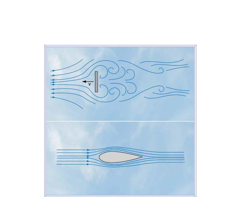
Figure 5.6 A flat plate moving through the air, at a right angle to the airflow, generates a very large amount of form drag.
94

ID: 3658
Customer: Oleg Ostapenko E-mail: ostapenko2002@yahoo.com Customer: Oleg Ostapenko E-mail: ostapenko2002@yahoo.com
CHAPTER 5: DRAG
The greater the disturbance created by the aircraft as it moves through the air, the greater will be the energy required to create the disturbance and the greater will be the form drag on the aircraft. If the disturbance can be minimised, form drag will be reduced.
An extreme example of the generation of form drag is the movement of a fat plate through the air, at a right angle to the airfow, as illustrated in Figure 5.6. In the situation shown, the drag will be almost entirely due to the vortices generated by the plate, and to the dynamic pressure, ½ ρv², acting on the plate’s frontal surface, against the plate’s direction of motion. So, form drag is a maximum, while skinfriction drag will be negligible.
Reducing Form Drag through Streamlining.
In the chapter on lift you learned that lines which show the direction of fow of a fuid at any particular moment are called streamlines. A body so shaped as to produce the least possible turbulence in the air fowing around it is said to be a streamlined shape. A streamlined shape will, consequently, generate far less form drag than a fat plate of the same frontal cross-sectional area
Therefore, in the design and manufacture of aircraft, the shapes of aircraft components, as well as the shape of the whole aircraft itself, are designed, where possible, to be of a form and proportion that will cause only a gradual change in the direction of the air which fows over them.
Aircraft components will, therefore, tend to be of a long, slender shape, with minimal frontal area, as depicted in Figure 5.7. Such streamlined shapes generate as little as 5% of the form drag produced by the fat plate.
However, long, thin shapes can have a signifcant surface area and, therefore, do give rise to skin-friction drag. So, obtaining the correct ratio between the length and thickness of a streamlined shape is crucial, if minimum parasite drag is to be achieved. The ratio of length to thickness is called the fneness ratio. For airspeeds up to
300 knots, it has been shown that a fneness ratio of about 4:1 is optimal.
An optimally-designed, streamlined aircraft component, meeting the airfow at a small angle of attack, will generate much less form drag than skin-friction drag.
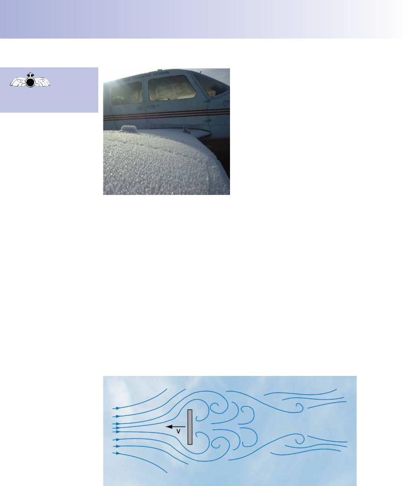
Figure 5.8 overleaf, illustrates how the form drag caused by an undercarriage wheel is reduced by ftting a streamlined spat.
Streamlining reduces form drag.
95
Order: 6026
Customer: Oleg Ostapenko E-mail: ostapenko2002@yahoo.com
Customer: Oleg Ostapenko E-mail: ostapenko2002@yahoo.com
CHAPTER 5: DRAG
Figure 5.8 The form drag generated by an undercarriage wheel may be reduced by fitting spats.
It is obviously of great importance that the form drag produced by aircraft components which are directly exposed to the relative airfow should be reduced to a minimum, as an aircraft will perform much more effciently if its total drag is low. Aerodynamicists have proven beyond doubt that enormous performance and effciency advantages are to be gained by streamlining exposed aircraft components such as undercarriage legs and wheel assemblies.
Increase in Form Drag with Increasing Angle of Attack.
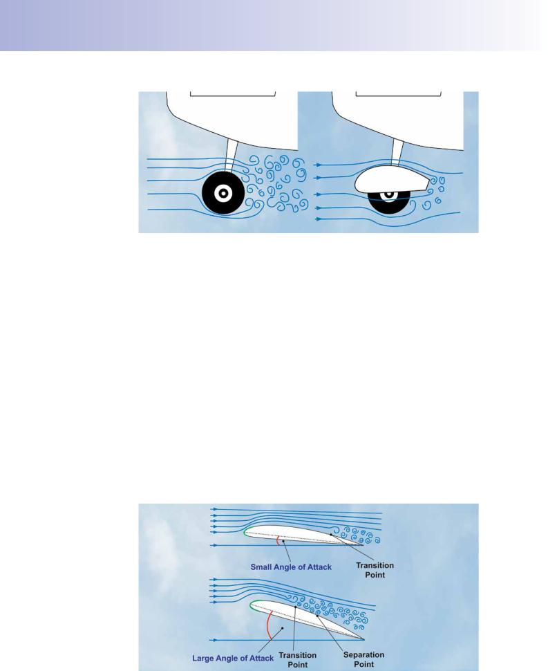
We have established, then, that the form drag generated by an aircraft increases in proportion as the air is disturbed by the aircraft’s passage. You will not be surprised to learn, therefore, that form drag increases as a wing’s angle of attack increases. You may remember that, as angle of attack increases, the separation point, at which the boundary layer breaks away from the wing, moves forward towards the wing’s leading edge, creating an increasing area of erratic and haphazard airfow, aft of the wing. As the angle of attack approaches the stalling angle (typically 16º for a light training aircraft without sophisticated lift augmentation devices), the turbulent wake behind the wing thickens, causing form drag to increase rapidly. Figure 5.9 illustrates this phenomenon. In order to keep things simple, we depict only the airfow above the wing. The increase in form drag with increasing angle of attack explains why drag increases markedly at the point of stall, to accompany the abrupt decrease in lift.
Figure 5.9 Form drag increases with increasing angle of attack.
96