

Text 24. Direct-current generators
The construction and operation of a d. с generator are practically the same as those of alternators, the main differences being the commutator action, the method of field excitation and the necessity of always having the armature — the rotating member. This latter is required to permit the commutator to function.
The commutator consists of a number of wedge-shaped copper segments fitted together around one end of the armature. The segments are separated from each other by some insulating material.
 s
a matter of fact thin sheets
of mica are widely used,
the two terminals of
each
armature coil are connected
to adjacent commutator
segments.
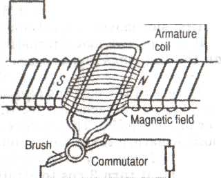
Fig.
8 shows an end view of
an armature, with commutator
and coil connections.
For the sake of clarity,
each armature
winding
is shown as a single Lead
loop.
s
a matter of fact thin sheets
of mica are widely used,
the two terminals of
each
armature coil are connected
to adjacent commutator
segments.
Fig.
8 shows an end view of
an armature, with commutator
and coil connections.
For the sake of clarity,
each armature
winding
is shown as a single Lead
loop.
Fig. 8 Field rheostat Magnet (field pole)
In practice, the brushes make contact on the outer surface of the commutators. The commutator progressively switches the brushes from one end of an armature coil to the other end, just as the coil starts to enter the opposite pole area. Thus although the direction of electron movement in the coil has reversed, the opposite end of the coil has been connected to the external circuit, direct current flowing out through the brush.
Direct-current generators are usually self-excited, some of the energy generated by the armature being used to energize the field windings. This is impossible in alternators, because the direction of the field flux must be constant; therefore direct current is required as a field excitation source.
Sufficient residual magnetism remains in the field poles to generate a small voltage when the armature starts to revolve. This current, fed into the field windings, is found to strengthen the magnetic field, which in turn causes more voltage to be developed in the armature. This process continues until the generator has been brought up to operating speed.
Notes
generator - генератор
commutator - колектор
armature - якір (магніту)
to permit - дозволяти
segment - частина колектора
insulting - ізоляційний
sheet - лист
mica - слюда
terminal - кінець
coil - котушка
loop - петля; цикл
just as the coil starts - саме тоді, коли котушка починає
to enter the opposite - входити в зону протилежного полюсу
to reverse - змінювати
to energize - пропускати струм
winding - обмотка
flux - потік
excitation - збуджування (струму)
Comprehension questions:
1. What is the difference between the construction and operation of d.c. generator?
2. What is the construction of the commutator?
3. What operation is impossible in alternators?
4. Why sufficient residual magnetism remains in the field poles?
ЛІТЕРАТУРА
1. Є.О. Мансі. Power and Mechanical Engineering. Electrical Engineering. Тексти допідручника з англійської мови для студентів і аспірантів немовних факультетів. Київ: Арій, 2008, с.39-77.
2. Peter Master. English Grammar and Technical Writing..Regional Printing Center of the U.S. Department of State, 2004.