

02 BOPs / Woods D.R 2008 rules-of-thumb-in-Engineering-practice (epdf.tips)
.pdf2.3 Liquid 51
2.3 Liquid
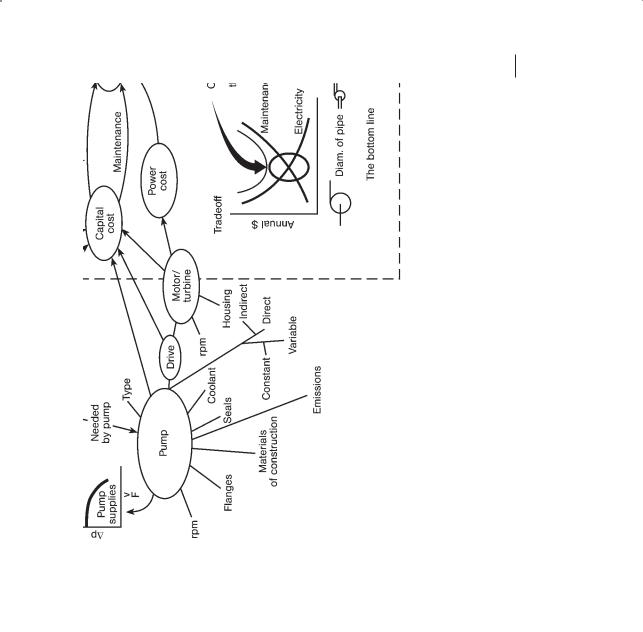
Overall selection and sizing factors summarized on the sizing map in Fig. 2.1. The ultimate choice is a tradeoff between the power to drive the pump and the maintenance and capital cost related to purchasing the pipe. The optimization is based on the annual operating cost of the pump–pipe system as a function of the diameter of the discharge pipe, or velocity of liquid in the discharge line optimization. This is illustrated in the lower RHS of Fig. 2.1. The analysis starts with the flowrate, the contaminants, the density and the Newtonian behavior of the liquid. The flowrate is related to the proposed liquid velocity and the diameter of the pipe. Central to all the decision making is the configuration, shown mid central in Fig. 2.1. The configuration depends on the layout of the equipment, the proximity of the pipe rack, the space available, the ergonomics and ease in maintenance, the need for and selection of instruments and control valves for process control, the length of pipe and the number and type of fittings, the vertical layout and the configuration and length of suction line. This all affects the pressure drop and the NPSH available for the pump.
The pressure drop (top LHS of Fig. 2.1) depends on the diameter, length and type of pipe and fittings, the elements for process control, the configuration, the velocity and the layout for NPSH. The latter, NPSH, depends on the vapor pressure, the temperature, the design of the vortex breaker, the NPSH required by the pump, the vertical component of the configuration. The resultant pressure drop expressed as a function of the volumetric flowrate summarizes the system needs.
The pump, shown in the lower LHS of Fig. 2.1, is selected based on the type, the rpm, the pressure the flanges can withstand, the materials of construction, seals and emissions, the coolant/lubricant and the type of drive; the housing, the rpm and the type of connection between the drive and the pump.
All these choices lead to capital and operating costs that become the objective function of the optimization, shown in the lower RHS of Fig. 2.1.
x Area of Application (M)
Centrifugal pumps: fluid viscosity I 300 mPa.s
end suction, single stage: 0.2 to 100 m; 0.05 to 4000 L/s; 0.05 to 0.7 kW/L/s; efficiency 40 to 60 %;
end suction, multistage: 50 to 800 m; 10 to 400 L/s; 0.2 to 10 kW/L/s; efficiency 40 to 60 %.
Peripheral pumps: 10 to 300 m; 0.1 to 2 L/s; 4 kW/L/s.
Centrifugal axial pumps: fluid viscosity I 300 mPa.s : 0.3 to 10 m; i 150 L/s; 0.1 kW/L/s.
Reciprocating pumps: fluid viscosity I 5000 mPa.s diaphragm or piston: 1 to 1000 m; I 50 L/s; 0.1 to 3 kW/L/s.
Gear pumps: fluid viscosity, usually above 10 Pa.s; 60 m; capacity depends on viscosity of liquid I 50 L/s
52 2 Transportation
Figure 2.1 Size-map for centrifugal pumps.
Rotary screw pumps (Progressing cavity pump; moyno pump): for shear sensitive; slurries; particle diameter I 5 cm., temperature I 80 hC; fluid viscosity, usually above 10 Pa.s; head 0.2 to 300 m; I 125 L/s; self priming; minimum foaming; pulsation-free flow. Tends to be a constant volume device.
Use centrifugal type when need to match variable flowrate with variable demand. Use positive displacement type to supply constant flowrate relatively independent of changes in pressure; when self priming is needed, and for insensitivity
to large variations in viscosity and density.
2.3 Liquid 53
x Guidelines
Centrifugal: Optimum exit pipe size-selection: pump liquids at i 1.5 m/s [$]
hydrocarbons with low conductivity I 0.3 m/s [S] Suction pipe of larger diameter to prevent cavitation.
NPSH requirement [m] = {rpm/(5400 volumetric flowrate [L/s])}1.33 Centrifugal pumps operate on their operating head-capacity curve. Head capac-
ity curves are independent of the fluid although the curve drops slightly at higher

54 2 Transportation
capacities for higher viscosity fluids. For centrifugal pumps, the drive power required and pressure at the exit flange depend on the fluid density.
Reciprocating pumps are constant volume devices producing essentially constant “pressure.”
Pressure drop for flow of liquid through pipes: 1 velocity head per 45 to 50 Length/diameter (F)
for water, 23 kPa/100 m pipe
Pressure allowance across a control valve for good operability : 20 to 50 % of the dynamic head loss or 70 to 140 kPa.
Pressure drop for flow of liquids through: shell and tube exchanger: 70 kPa,
plate exchanger: 50 kPa, dialysis: 50 to 10 MPa, RO: 0.1 to 4 MPa, Filter press: 70 kPa,
Porous bed: 0.3 to 7 kPa/m depth of bed/L/m2 s Usual: 5 to 10 Bed Volumes per h; 1 to 10 L/m2 s usually limit it to I 80 kPa.
Similitude for centrifugal devices: volumetric flowrate ratios = (diameter of impeller ratio) times (impeller rpm ratio); head ratios = (diameter ratio)2 times (the impeller rpm ratio)2; power ratio = (diameter ratio)3 times (impeller speed ratio)3.
Positive displacement reciprocating pumps: “head”-capacity “curve” is almost vertical: flowrate decreases only slightly with higher discharge pressure. Although we usually consider “head” for centrifugal pumps, pressure is more appropriate for positive displacement. Suction velocity I 1 m/s.
Gear pumps: power: for pressure I 20 MPa: 58 W.s/g; for pressure i 20 MPa: 120 W.s/g.
Rotary screw (moyno) pumps: shear typically 50–70 s–1/100 rpm. For highly abrasive (plaster grout, emery dust slurries keep average velocity 1–1.5 m/s; mediumly abrasive (clay slurry, sludges) average velocity 1.8–3 m/s; lightly abrasive 3–4.5 m/s. Reduce rpm as capacity increases: use 1200 rpm for I 0.8 L/rev (15 L/s); I 300 rpm for i 10 L/rev (50 L/s).
xGood Practice
Don’t let centrifugal pumps run at I 10 % of optimum design where efficiency is highest. Consider a pulsation dampener in discharge line from a reciprocating pump. Prevent flashing downstream of control valves. Control volumetric output from a positive discharge pump by a control value on a recycle line from discharge to suction. Trim the impellers for continuous turndown operation. For systems pumping edible oils include steam blowout to clear the lines.
Centrifugal pumps: head capacity curve should not be too flat if pump capacity is controlled by valve positioner. Select pump such that a larger diameter impeller could be installed later. An increase in flowrate causes an increase in required NPSH and a decrease in available NPSH.
Rotary pumps: sometimes NPSH is expressed as Net Inlet Pressure Required, NIPR, (or available NIPA), expressed as kPa absolute.

2.3 Liquid 55
Gear pumps: Higher the viscosity, the lower the rated rpm. On the discharge install a check valve and an expansion chamber or pulsation dampener, the latter to reduce noise. For infrequent operation, operating pressure should be 20–30 % I rated pressure. For continual operation, operating pressure I I rated pressure and rpm I rated rpm. Never allow them to run dry. For startup, idle off line for about an hour.
Rotary screw (moyno) pumps: Stator has one more lobe/screw than the rotor; reduce rpm for abrasives; starting torque = 4 q initial torque. If particles are present, try to minimize the abrasion by using viscosity i 5000 mPa.s. Backflow or “slip” is reduced as viscosity increases. NPSH problems are usually not important except for suction lift, pumping from a vacuum and fluid vapor pressures of i 15 kPa.
x Trouble Shooting
Centrifugal pumps: “No liquid delivery”: instrument error/not primed/cavitation/ supply tank empty. “Liquid flowrate low”: instrument error/[cavitation]*/non-con- densibles in liquid/inlet strainer clogged. “Intermittent operation”: [cavitation]*/ not primed/non-condensibles in liquid. “Discharge pressure low”: instrument error/non-condensibles in liquid/speed too low/wrong direction of rotation (or impeller in backwards if double suction). “Power demand excessive”: speed too high/density liquid high/required system head lower than expected/viscosity high.
Peripheral pumps: “No liquid delivery”: instrument error/pump suction problems/ suction valve closed/impeller plugged. “Liquid flowrate low”: instrument error/ speed too low/incorrect impeller trim/loose impeller. “Discharge pressure low”: instrument error/speed too low/incorrect impeller trim/loose impeller. “Power demand excessive”: speed too high/improper impeller adjustment/impeller trim error.
Reciprocating pumps: “No liquid delivery”: instrument error/excessive suction lift/ [cavitation]*/non-condensibles in liquid. “Liquid flowrate low”: instrument error/ excessive suction lift/[cavitation]*/non-condensibles in liquid.
Rotary pumps: “No flow”: instrument error/[pump not turning]*/[pump not primed]*/relief valve not adjusted correctly or dirt keeping the relief valve open/wrong direction of rotation/[cavitation]*/excessive suction lift.“Flow I design”: instrument error/rpm too low/air leak via bad seals or faulty pipe connections/[ flow going elsewhere]*/[high slip]*/suction line clogged/insufficient liquid supply/[air or gas in liquid]*. “Starts but loses prime”: air leakage/liquid vaporizing in suction line/insufficient liquid supply.“Noisy operation”: [cavitation]*/[air or gas in liquid]*/[mechanical noise related to pump]*/relief valve chatter/drive component noise. “Power i design”: higher viscous losses than expected/pressure i design/fluid viscosity i expected/fluid “sets up” or solidifies in the line or pump during shut down/fluid builds up on pump surfaces/rotating elements bind. ‘Short pump service life”: [corrosion]*/abrasives present/speed and pressures i design/lack of lubrication/misalignment.

56 2 Transportation
Gear pumps: usually performance does not break down suddenly; gradual decrease in performance. Are particularly susceptible to cavitation and erosion. “Low discharge pressure”: instrument error/leakage/low drive power/faulty reliefvalve setting/[internal leakage]*/[abrasion]*. “No liquid delivery”: instrument error/suction line clogged/drive shaft/check-valve fault. “Low liquid delivery”: instrument error/drive power low/[internal leakage]*/[abrasion]*/[cavitation]*. “Noisy”: entrained air in liquid/liquid doesn’t drain from grooves/misaligned drive and pump shafts/faulty bearings/loose mountings/resonance because mating frequency of gears = natural frequency of gear train/rpm too high/worn parts/[cavitation]*. “Overheating”: liquid viscosity higher than expected/liquid feed temperature too low/faults in drive system such as misaligned drive and pump shafts. “Shaft won’t rotate”: drive system not working/material in pump not melted/temperature too low/seized pump. “Significant oscillation in pump suction pressure”: instrument wrong/faulty control system/suction pressure set-point too low for the process. “Pump discharge pressure oscillates”: instrument wrong/ starved feed to pump/change in viscosity of feed/damaged pump internals. “Inadequate volumetric efficiency”: decrease in viscosity/pressure in upstream process increase/worn pump.
Rotary screw (moyno) pumps: “No liquid delivery”: instrument error/wrong direction of rotation/insufficient suction lift/clogged inlet/air leaks on suction/faulty pressure relief valve/worn pump. “Rapid wear”: discharge pressure too high/ pump runs dry/incorrect materials of construction/speed too high for abrasives/viscosity too low for abrasives. “Noisy”: insufficient feed flowrate/air leak in suction/gas in feed liquid/speed too high/poor alignment. “Excessive power”: rpm too fast/liquid viscosity i design/operating pressure i design/discharge line plugged/stator expanded or swollen. “Failure of the stator”: bond failure (pH i 10 or local hot spot)/temperature i design. “Initially OK but gradual increase in power needed”: swelling of elastomeric stator coating because of chemical attack.
[Abrasion]*: grit in liquid/[cavitation]*/pH different from design.
[Air or gas in liquid]*: [ fluid vaporizes]*/air bleed missing/fluid gasifies under operating conditions/leaks in pumps or piping.
[Air lock]*: [ fluid vaporizes]*/air bleed missing/fluid gasifies under operating conditions.
[Cavitation]*: [ fluid vaporizes]*/pump rpm too fast/suction resistance too high/ clogged suction line/suction pressure too low/liquid flowrate higher than design/entrained gas.
[Corrosion]*: see Section 1.3.
[Flow goes elsewhere]*: relief valve faulty or jammed open/discharge flow diverted to wrong branch line.
[Fluid vaporizes]*: [NPSH supplied too small]*/fluid viscosity i design/fluid temperature i design/vapor pressure of fluid too high.
[High slip]*: clearance between rotors i specs/worn pump/pressure i design. [Internal leakage]*: excessive clearance between the gear and sides or end plates/ [abrasion]*

2.4 Gas–Liquid (Two-phase Flow) 57
[Mechanical noise related to pump]*: wrong assembly/pump distortion because of wrong piping installation/pressure i rating/worn bearings/worn gears/loose gears/twisted shaft/sheared keys/worn splines.
[NPSH supplied or NIPA supplied too small]*: strainer clogged/temperature too hot/ inlet line clogged/inlet line diam. too small or length too long/atmospheric pressure I design.
[Pump not primed]*: valve on inlet line closed/inlet line clogged/air leaks/pump rpm too slow/liquid drains or siphons out during off-periods/check-valve missing or faulty/[air lock]*/worn rotors.
[Pump not turning]*: drive motor stopped/key sheared or missing/belt drive broken/pump shaft broken.
2.4
Gas–Liquid (Two-phase Flow)
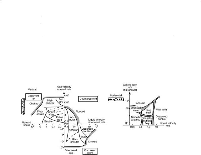
Figure 2.2 illustrates different flow regimes for vertical cocurrent up flow, vertical countercurrent and horizontal flows. See also boilers, Section 3.3; evaporators, Section 4.1, and two-phase pipe/tube reactors, Section 6.5. Other characteristics of GL systems are given in Section 1.6.1.
x Guidelines
Design so that the two-phase flow is in the correct regime. Dp for two-phase flow is tricky to predict because the value depends on the flow regime, whether the individual gas and liquid flows are laminar or turbulent, on the pressure (because this affects the gas density), the mass fraction of the flow that is gas, x, and upon whether the flow is horizontal, vertical, cocurrent or countercurrent. In general the approach is that the actual pressure loss per unit length of pipe = (Dp/L)2@ = @2G(Dp/L)G = @2L(Dp/L)L where the last two terms are, respectively, “corrections” to the pressure drop assuming only the gas or only the liquid are flowing in the pipe. Usually, when the mass fraction of gas, x i 0.75 we tend to use the former and vice versa.
The correction factors, @G2 or @L2 are usually i 1 and can be i 1000. The correlations (and approximate factors given here) apply usually for horizontal flows in the slug and bubble regime with the factors being too high for the stratified, wavy and spray flow regimes and too low for the annular flow regime.
Example values for @L2 as a function of mass fraction gas and absolute pressure are given in Table 2.1.
Thus, from Table 2.1, if the mass fraction of gas flowing in the line is about 0.2 and, if we estimated the pressure drop based on only the liquid flowrate to be 0.05 kPa, then for two-phase flow at 0.7 MPa abs we might expect the actual pressure drop to be perhaps 20 times this value or 1 kPa. If, from Fig. 2.2, we estimate that the flow regime is annular flow, then the actual pressure drop may be even larger.
582 Transportation
Table 2.1 Correction factor, @L2, for two-phase flow based on the liquid phase pressure drop.
Mass fraction gas |
Absolute pressure, MPa abs |
|
|
|
|
|
|
|
|
|
0.1 |
0.7 |
3.4 |
14 |
0.01 |
3.4–5 |
1.2–3 |
2 |
1.2 |
0.1 |
12–30 |
3–15 |
5 |
1.7 |
0.5 |
80–200 |
8–65 |
18 |
3.5 |
|
|
|
|
|
Figure 2.2 Regions for two-phase flow.
x Good Practice
Avoid slug flow. Avoid the use of inclined lines, use either vertical or horizontal. Two-phase flow over a packing is given in Section 6. 17, trickle bed reactors.
2.5
Pumping Slurries: Liquid–Solid Systems
Related topic, slurry reactors, Section 6.7.
x Area of Application (F)
Solid concentration 25–65 % w/w; solid particle size: 20–300 mm. For finer particle size, watch for non-Newtonian behavior. For higher concentration, consider short pumping runs only; for small concentrations, beware of settling out. For larger particles, watch for settling out.

2.6 Solids 59
x Guidelines
Pumping velocity: 1 to 4 m/s, usually 1.4–1.8 m/s; 0.06 to 0.7 kW/Mg/h per km distance. Loading 0.3–1.7 kg solids/kg water. Economic tradeoff between solids loading and pumping costs. Try to use the heterogeneous flow regime and consider adjusting pH to alter stability of suspension. Minimum pipe diameter is ten times the largest diameter particle in the slurry.
x Good Practice
Include high pressure water purge for both forward and reverse flow at velocity i 1 m/s. Avoid dead ends and pockets. Arrange for flushing of the line with water; place nozzles on the top of the primary loop. Avoid flow restrictions, including orifices.
2.6 Solids
Choice depends on particle characteristics (size, flowability, corrosiveness, abrasiveness, handling characteristics and safety-hazard (static electrification, fumes, flammability and vertical vs. horizontal distance). Related topic Section 2.5, mixing Section 7.4 and bins for storage, Section 10.3.
Johanson’s1), 2) definitions of terms used to characterize solid particles are given in Section 1.6.4. The important terms are AI, RI, HI, FRI, FDI, BDI, CI, RAS and
SBI.
x Area of Application (M, F)
Belt conveyors: I 10h incline; 10 to 100 m horizontal distance; capacity 3–270 kg/s. OK for most diameters of particles but not for particles that cake or are light and fluffy.
Bucket/belt elevators: usually for i 25 m vertical; 15 to 150 Mg/h; usually not for particles I 150 mm diameter particles but not for particles that cake or are light and fluffy.
Screw conveyors: 2–75 m horizontal distance; 0.3–275 kg/s. Not for particles that cake or are light and fluffy. Can be used for inclines up to 20h.
Vibratory feeder: I 20 m; 1–400 Mg/h; not for light and fluffy materials or particles I 150 mm diameter.
Apron feeder: I 18h incline; 2–12 m horizontal; 10–150 Mg/h; not for particles that cake or are light and fluffy or are fine with I 150 mm diameter. pneumatic transportation: limited by solids loading that plugs pipe.
Dilute phase: pressure: continuous: particle diameter 60 mm–0.3 cm; pressure drop I 100 kPa. Distance I 600 m. One point collection and several point delivery.
1) J. R. Johanson, 2002, “Troubleshooting bins, |
2) J. R. Johanson, 2000, “Smooth out solids |
hoppers, feeders”, Chem. Eng. Prog. April, |
blending problems”, Chem. Eng. Prog. April |
pp. 24–36. |
p. 21. |

60 2 Transportation
Dilute phase: vacuum: continuous: particle diameter 60 mm–0.3 cm; Dp pressure drop I 50 kPa. Distance I 50 m. One point delivery and several point collection. Use for hazardous solids.
Dense phase: pressure: batch: particle diameter 60 mm–0.3 cm; pressure drop 550–700 kPa. High capacity (I 10 kg/s) over long distances I 2300 m. For materials that degrade easily, are highly abrasive. Not for granular materials that have a high percentage of fines that would cause the discharge line to block.
x Guidelines
Caution for all: dust explosions: dust explosion potential for particle diam I 200 mm. Minimum ignition temperature i 300 hC; minimum ignition energy 10–30 mJ.
Belt conveyors: keep speeds I 1 m/s for fines; otherwise speeds in the range 2.7–4 m/s; burden thickness [cm] = 0.17 (volumetric capacity, dm3/s)/ {(Belt speed, m/s)(Belt width, m)}. Belt width 0.5–0.8 m.
Speed 0.8–2 m/s. Power: 0.02 to 0.4 kW/Mg/h per km horizontal distance. Bucket conveyor: vertical: velocity I 1.5 m/s; for material of density 0.4 Mg/m3 capacity I 16 kg/s; for 2 Mg/m3 capacity I 85 kg/s or I 40 m3/s. Power 0.15–0.35 kJ/kg or 0.013–0.023 kJ/kg.m of height.
Screw conveyors: 10–120 rpm and trough loading 15–95 % depending on the particle size, flowability, abrasiveness. Diameter 0.3–0.4 m. Power 10–20 kW/Mg/h per km horizontal distance. Can use hollow screws with heat exchange media flowing inside the screw. See Section 3.3.
Screw conveyor feeder from bottom of hopper: capacity is very sensitive to screw flight clearances for moderately incompressible solids (whose FDI and BDI differ by I 5 %). Hopper discharge active flowrate of solids limited to about one screw diameter (if hopper discharge is i 1 screw diameter there is a potential for cohesive solids to bridge and free-flowing solids to cause overload of drive).
Belt feeder from bottom of hopper: active flowing solids discharging from the hopper are on the downstream side of the belt; upstream solids in hopper may be stationary. The gap between the belt and the interface edge = 0.021 cm/cm in the direction of solids movement.
Vibrating feeder from bottom of hopper: active flowing solids discharging from the hopper are on the downstream side of the feeder; upstream solids in hopper may be stationary.
Rotary, star valve feeder: Used especially as solids feeders for dilute phase pneumatic conveying to provide an air lock and to feed solids. Seal/wear depends on Dp and abrasiveness of powder. For pressure systems keep Dp I 80 kPa; for vacuum systems Dp I 40 kPa. Provide an air vent to take the air loss away from the gravity flow of the solids and to control the filling of the star. For granular particles, prefer an offset-feed rotary valve; for cohesive particles, more difficult to handle; prefer a blow-through rotary valve. Cohesive particles will tend to seal a rotary valve and minimize air leakage. Not recommended for abrasive powders.