


Ä
SERVICE PROCEDURES
Procedures for the removal and installation of the driveshafts are essentially the same for all front wheel drive vehicles. Each driveshaft has a spring within the inboard Tripod C/V joint that maintains constant engagement with the transaxle. This allows the drive shaft to be removed without dismantling part of the transaxle.
CAUTION: Boot sealing is vital to retain special lubricants and to prevent foreign contaminants from entering the C/V joint. Mishandling, such as allowing the assemblies to dangle unsupported, pulling or pushing the ends can cut boots or damage C/V joints. During removal and installation procedures always support both ends of the driveshaft to prevent damage.
DRIVESHAFTS, REMOVE INSTALL
HUB NUT REMOVAL
Hub nut removal and installation is the same for all front wheel drive vehicles. For installation see Hub
Nut Assemblies Install.
(1) Remove cotter pin, lock and spring washer (Fig.
3).
Fig. 3 Remove Cotter Pin, Nut Lock, & Spring
Washer
(2)Loosen hub nut and wheel nuts while vehicle is on floor and brakes applied (Fig. 4).
(3)Raise vehicle, see Hoisting in Lubrication and Maintenance, Group 0 of this service manual.
(4)Remove hub nut, washer, wheel and tire assembly (Fig. 5).
DRIVESHAFT ASSEMBLIES REMOVE
Inboard C/V joints have stub shafts splined into the differential side gears, or splined into the intermediate shaft on the right side of an equal length system.
SUSPENSION/DRIVESHAFTS 2 - 27
Fig. 4 Loosen Hub Nut & Wheel Nuts
Fig. 5 Remove Hub Nut & Washer Loosen Shaft
Driveshafts are retained in the side gears by a constant spring force provided by a spring contained within the inboard C/V joints.
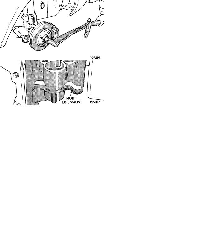
(1)For removal of right driveshaft, the speedometer pinion must be removed BEFORE shaft removal (Fig. 6).
(2)Remove clamp bolt securing ball joint stud into steering knuckle (Fig. 7).
(3)Separate ball joint stud from steering knuckle by prying against knuckle leg and control arm (Fig. 8).
CAUTION: Do not damage ball joint or C/V joint boots (Fig. 8).
(4) Separate outer C/V joint splined shaft from hub by holding C/V housing while moving knuckle(hub) assembly away (Fig. 9).
CAUTION: Do not pry on or otherwise damage wear sleeve on outer C/V joint.

2 - 28 SUSPENSION/DRIVESHAFTS |
|
Ä |
|
Fig. 6 Remove Speedometer Pinion Clamp (For
Right Driveshaft).
Fig. 7 Remove Ball Joint to Steering Knuckle Clamp Bolt
(5) Support assembly at C/V joint housings. Remove by pulling outward on the inner joint housing.
DO NOT PULL ON SHAFT (Figs. 10 and 11).
The driveshaft, when installed, acts as a bolt and secures the hub/bearing assembly. If the vehicle is to be supported or moved on its wheels, install a bolt through the hub to ensure that the hub bearing assembly cannot loosen.
Fig. 8 Separate Ball Joint from Knuckle
Fig. 9 Separate Outer C/V Joint Shaft from Hub
Fig. 10 Removing Driveshaft Assembly Unequal
Length
DRIVESHAFT ASSEMBLIES INSTALL
CAUTION: See Wear Sleeve and Seal Lubrication in Front Suspension and at end of this Group BEFORE driveshaft installation.

Ä |
|
SUSPENSION/DRIVESHAFTS 2 - 29 |
|
Fig. 11 Removing Driveshaft Assembly Equal
Length
(1) Hold inner joint assembly at housing (Figs. 11 and 12) while aligning and guiding the inner joint spline into the transaxle or intermediate shaft assembly. On Equal Length System vehicles only, be sure that the rubber washer seal is in place on the right inner C/V joint (Fig. 1).
Fig. 12 Installing Inner Shaft into Transaxle
CAUTION: Seal/Wear Sleeve Lubrication During any service procedures where knuckle and driveshaft are separated. Thoroughly clean seal and wear sleeve with suitable solvent (solvent must not touch boot) and lubricate both components prior to installing driveshaft. Lubricate wear sleeve and seal with Mopar Multi-Purpose Lubricant, or equivalent.
Apply on the full circumference of the Wear Sleeve a bead of lubricant that is 6 mm (1/4 in.) wide to seal contact area (Fig. 13). Fill the seal lip to housing cavity on bearing seal with lubricant. Lubricant is to be applied around complete circumference of the seal, and seal lip should be wet with lubricant (Fig. 13). Use Mopar Multi-Purpose Lubricant or equivalent for lubrication of the Wear Sleeve and Bearing Seal.
(2) Push knuckle (hub) assembly out and install splined outer C/V joint shaft in hub (Fig. 14).
CAUTION: Steering knuckle clamp bolt shown in (Figs. 14 and 15) is Prevailing Torque Type, original
Fig. 13 Seal & Wear Sleeve Lubrication
or equivalent bolt must be installed during assembly.
Fig. 14 Install Outer Shaft into Hub
(3)Install knuckle assembly on ball joint stud (Fig.
15).
(4)Install and tighten clamp bolt to 95 NIm (70 ft. lbs.) torque (Fig. 16).
(5)Install speedometer pinion (Fig. 17).
(6)Fill differential with proper lubricant (see Lubrication and Maintenance Group 0).
(7)Install hub nut assembly.
(8)If after installing the driveshaft assembly, the inboard boot appears collapsed or deformed. Vent the inner boot by inserting, a round tipped small diameter rod between the boot and shaft. If necessary, massage the boot to remove all puckers being careful not to allow dirt to enter or grease to leave the boot cavity. The clamp must be removed and discarded be-
2 - 30 SUSPENSION/DRIVESHAFTS |
|
Ä |
|
Fig. 15 Install Knuckle Assembly on Ball Joint Stud
Fig. 16 Tighten Clamp Bolt
fore the rod can be inserted. After venting, install a new Service Clamp. (See Boots Install section at the end of this group for details).
HUB NUT INSTALL
The front wheel hub nuts use a lock and cotter pin to maintain proper wheel bearing preload and prevent the nut from backing off. Install the assembly as follows:
(1)Install washer and hub nut after cleaning foreign matter from threads (Fig. 18).
(2)With brakes applied, tighten hub nut to 245 NIm (180 ft. lbs.) torque (Fig. 19).
(3)Install lock, spring washer and new cotter
Fig. 17 Install Speedometer Pinion
Fig. 18 Install Washer & Hub Nut
Fig. 19 Tighten Hub Nut
pin. Wrap cotter pin prongs tightly around nut lock (Fig. 20).