

Ä |
|
SUSPENSION/DRIVESHAFTS 2 - 41 |
|
Fig. 8 Installing New Circlip
(10)On G.K.N. units insert the new circlip, provided with kit in shaft groove. Do not over expand or twist circlip during assembly (Fig. 8). The S.S.G. unit has a reusable circlip retainer that is an integral part of driver assembly.
(11)Position outer joint on splined end with hub nut on stub shaft. Engage splines, and tap sharply with mallet (Fig. 9).
(12)Check that circlip is properly seated by attempting to pull joint from the shaft.
(13)Locate large end of boot over joint housing checking that boot is not twisted.
(14)Fasten boot to housing. See Boots Install.
Fig. 9 Position Joint onto Shaft Splines
INTERMEDIATE SHAFT ASSEMBLY RECONDITION
Reconditioning of the Intermediate Shaft Assembly (Fig. 1) for the Equal Length Drive Shaft System vehicles is the same for the manual and automatic transaxles.
INTERMEDIATE SHAFT ASSEMBLY
Remove
(1)Remove right driveshaft. See Driveshaft Assemblies Remove.
(2)Remove speedometer pinion from the extension housing (Fig. 2).
(3)Remove the two bolts which mount the bearing assembly bracket to the engine block (Fig. 1).
Fig. 1 Intermediate Shaft Assembly

2 - 42 SUSPENSION/DRIVESHAFTS |
|
Ä |
|
Fig. 2 Remove Speedometer Pinion
(4) Remove assembly from transaxle extension by pulling outward on the yoke (Fig. 3).
Fig. 3 Removing Intermediate Shaft Assembly
UNIVERSAL JOINT AND ROLLER
Disassemble
(1)Mark relationship of shaft to shaft to ensure proper alignment at assembly. Apply penetrating oil to bushings and remove snap rings.
(2)Support yoke in vise and place a socket large enough to receive bushing on top of yoke. A 1-1/8 inch socket is suitable (Fig. 4).
(3)Striking socket with hammer will cause yoke to move down and bushing to move up out of yoke into socket.
(4)After removing one bushing, turn parts in a vise and remove other bushing in same manner.
Fig. 4 Disassemble Universal Joint
Fig. 5 Assemble Universal Joint
Assemble
(1)Hold cross in position between yoke ears with one hand and start one bushing assembly into yoke with other hand (Fig. 5).
(2)Continue to hold cross in position, then hammer bushing assembly into yoke and install snap ring.
(3)Install opposite bushing and snap ring in the same manner.
(4)Repeat process for stub shaft yoke after aligning marks on yoke and shaft.

Ä |
|
SUSPENSION/DRIVESHAFTS 2 - 43 |
|
BRACKET, BEARING, AND SLINGER ASSEMBLY
Disassemble
(1)Remove the two screws that hold the bearing assembly to the support bracket.
(2)Press the intermediate shaft out of the bearing assembly and outer slinger. Do not dent or damage the inner slinger. Also avoid damaging the end of the stub shaft, the rubber seal on the right driveshaft mates with this surface. Excessive wear to the rubber seal would result and allow moisture to enter, corroding the internal splines.
(3)If either slinger is damaged, it should be replaced. Carefully press the shaft through the slinger, discard the slinger.
The bearing assembly is not serviceable and must be replaced as an assembly.
Assemble
(1) Place new slinger on stub shaft and drive it on until it bottoms out on the shoulder of the shaft (Fig. 6). A tool for this purpose can be fabricated from a piece of pipe that has the dimensions noted in (Fig. 6).
CAUTION: Do not dent or bend the slinger during this installation, since it could prevent the bearing assembly from seating properly.
Fig. 6 Slinger Installation Intermediate Shaft
(2) Press bearing assembly into position on the shaft, there should be a minimum of 1 mm (1/32 in.) clearance between slinger and bearing assembly when properly installed.
CAUTION: Apply pressure only to the inner race of the bearing during this procedure. Or damage may result which could cause premature bearing failure.
(3) Press the outer slinger into place with the same tool used for bearing installation. The slinger must bottom out on the shoulder of the shaft.
INTERMEDIATE SHAFT ASSEMBLY
Install
(1) Securely fasten bracket to bearing assembly and tighten to 28 NIm (21 ft. lbs.) torque. Figs.7 and 8 (Also see Fig. 1).
Fig. 7 3.3L Intermediate Driveshaft Bearing Brack-
ets, Position
(2)Hold the stub yoke while aligning and guiding the splined end into the transaxle (Fig. 9).
(3)Swing the bracket into position on the engine and loosely install the screws through the slotted holes.
(4)Push the intermediate shaft assembly into the transaxle as far as it can travel. Hold the assembly in
this position and tighten the screws (bracket to engine block) to 54 NIm (40 ft. lbs.) torque. This will ensure full seal engagement between the journal on the intermediate shaft and the seal in the transaxle extension.
(5)Distribute a liberal amount of grease in side spline and pilot bore on bearing end of intermediate shaft. Use MOPAR Multi-Purpose Lubricant, or equivalent.
(6)Install speedometer pinion (Fig. 10).
(7)Install right driveshaft. See Driveshaft Assemblies Install.

2 - 44 SUSPENSION/DRIVESHAFTS |
|
Ä |
|
Fig. 8 2.5L Turbo and 3.0L Intermediate Driveshaft
Bracket (Typical)
Fig. 9 Installing Intermediate Shaft Assembly
C/V JOINT BOOTS Handling and Cleaning
It is vitally important during any service procedures requiring boot handling. That care be taken not to puncture or tear the boot by over tightening clamps, misuse of tool(s) or pinching the boot. Pinching can occur by rotating the C/V joints (especially the tripod) beyond normal working angles.
The driveshaft boots are not compatible with oil, gasoline, or cleaning solvents. Care must be taken that boots never come in contact with any of these liquids. The only acceptable cleaning agent for driveshaft boots is soap and water. After washing, boot must be thoroughly rinsed and dried before reusing.
BOOTS INSPECT
Noticeable amounts of grease on areas adjacent to or on the exterior of the C/V joint boot. Is the first indication that a boot is punctured, torn or that a
Fig. 10 Install Speedometer Pinion
clamp has loosened. When a C/V joint is removed for servicing of the joint. The boot should be properly cleaned and inspected for cracks, tears and scuffed areas on interior surfaces. If any of these conditions exist, boot replacement is recommended.
BOOTS INSTALL
THE HARD PLASTIC BOOTS REQUIRE APPROXIMATELY 100 TIMES THE CLAMPING FORCE OF THE RUBBER BOOT. THE CLAMPS USED ON THE RUBBER BOOTS DO NOT HAVE THE TYPE OF LOAD CAPACITY REQUIRED TO SEAL THE HARD PLASTIC BOOTS AND SHOULD NOT BE USED FOR THIS PURPOSE.
Rubber boots appear only on the inner joints of certain driveshafts.
Rubber boots must be serviced with the strap and buckle clamp. Use the Clamp Installer, Special Tool C-4653. Proceed with the boot installation as follows:
(1)Slide the small end of the boot over the shaft. Position the boot to the edge of the locating mark or groove, whichever is appropriate (Fig. 1).
(2)Install the C/V joint. See Inner or Outer C/V Joint Assemble.
(3)Slide the large diameter of the boot into the locating groove (Fig. 6).
(4)Wrap binding strap around boot twice, PLUS 63 mm (2-1/2 inches) (Fig. 2).
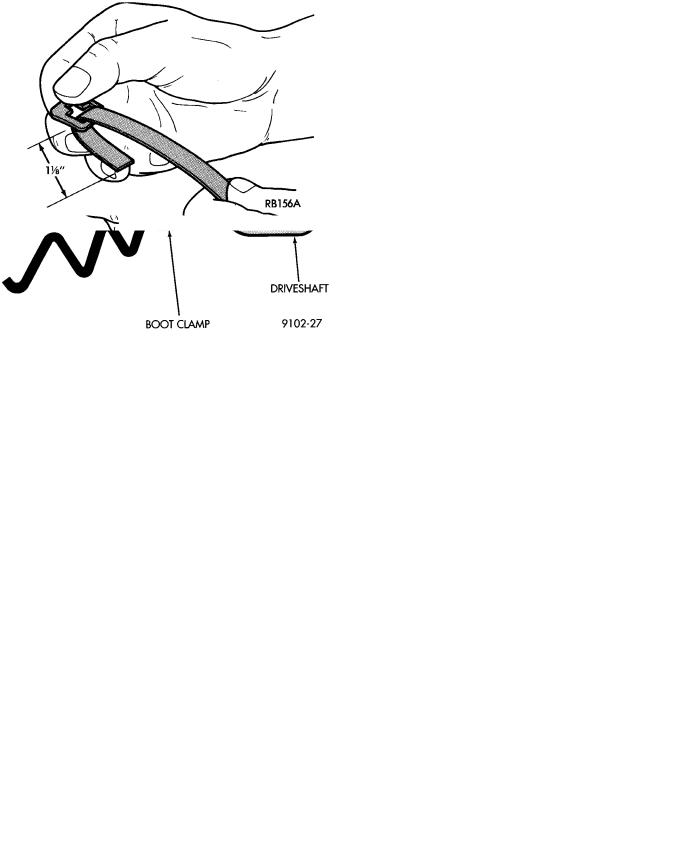
(5)Pass the strap through the buckle and fold it back about 29 mm (1-1/8 inches) on the inside of the buckle (Fig. 3).
(6)Put the strap around the boot with the eye of the buckle toward you (Fig. 4). Wrap the strap
Ä |
|
SUSPENSION/DRIVESHAFTS 2 - 45 |
|
Fig. 1 C/V Joint Boot Positioning G.K.N.
Fig. 2 Measure & Cut Binding Strap
Fig. 3 Install Buckle on Strap
around the boot once and pass it through the buckle, then wrap it around a second time also passing it
Fig. 4 Wrap Strap (through Buckle Eye) Twice
Fig. 5 Fold Strap Lightly to Keep Position
through the buckle.
(7)Fold the strap back slightly to prevent it from slipping backwards (Fig. 5).
(8)Open the tool all the way and place strip in narrow slot approximately 13 mm (1/2 inch) from buckle (Fig. 6).
(9)Hold the binding strap with the left hand and push the Tool forward and slightly upward. Then fit the hook of the Tool into the eye of the buckle (Fig. 7).
(10)Tighten the strip by closing the tool handles (Fig. 8). Then rotate the tool (handles) downward while slowly releasing the pressure on the tool handles. Allow the tool (handles) to open progressively. Then open the tool entirely and remove them sideways.
(11)If the strap is not tight enough, engage the tool a second or even a third time, always about 13 mm (1/2 inch) from the buckle (Fig. 9). When tightening always be careful to see that the strap slides in

2 - 46 SUSPENSION/DRIVESHAFTS
Fig. 6 Open Tool, Position Strap in Narrow Slot 1/2 Inch from Buckle
Fig. 7 Push Tool Forward & Fit into Buckle Eye
Fig. 8 Tighten Strap
a straight line and without resistance in the buckle, that is without making a fold. An effective grip will be obtained only by following the above instructions.
Ä
Fig. 9 Tighten Strap (if Required)
(12) Fig. 10 shows WHAT NOT TO DO, NEVER fold the strap back or bring the tool down while tightening, this action will break the strap.
Fig. 10 What Not to Do
(13) Fig. 11 shows how to pull the tool down while releasing the pressure on the tool handle.
Fig. 11 Correct Tightening Procedure

Ä |
|
SUSPENSION/DRIVESHAFTS 2 - 47 |
|
(14) If the strip is tight enough. Remove the tool sideways and cut off the strap 3 mm (1/8 inch), so that it does not overlap the edge of the buckle. Complete job by folding the strip back neatly (Fig. 12).
Fig. 12 Cut Strap 1/8 Inch from Buckle
(15) Fig. 13 shows the finished binding strap type clamp in position, correctly fitted and unable to come loose.
Fig. 13 Correctly Installed Clamp
(16)After attaching the C/V joint boot to the shaft. Install the inner or outer C/V joint following procedures under Inner C/V Joint Assemble or Outer C/V Joint Assemble.
(17)Slip the large end of the boot on the housing and align it in the boot groove.
(18)Repeat steps 2 - 13 for boot clamping.
S.S.G. C/V joints use two different type boots, one is made of plastic and the other of rubber. The plastic boot requires a heavy duty clamp and Installer, Special Tool C-4975. The soft boot requires a clamp with round edges that prevents the clamp from cutting the boot. Proceed with boot installation as follows.
The hard plastic boots used on the G.K.N. C/V Joints. Also use this procedure for installation of the boot clamp to C/V Joint.
LEFT INNER, LEFT AND RIGHT OUTER C/V JOINT WITH PLASTIC BOOTS
(1)Slide small clamp onto shaft.
(2)Position small end of boot over interconnecting shaft with lip of boot in third groove, towards center of interconnecting shaft (Fig. 14).
(3)Position clamp evenly over boot. Place clamp installer Tool C-4975 over bridge of clamp and tighten
Fig. 14 Boot and Clamp Positioning S.S.G.
the nut until the jaws of the tool are closed completely, face to face (Fig. 15).
Fig. 15 Closing Clamp Bridge
(4)After attaching the boot to the shaft. Install the C/V joint following the procedure outlined under Inner C/V Joint Assemble or Outer C/V Joint Assemble.
(5)Position the large end of boot on housing and install clamp, crimp bridge of clamp with Crimper, Special Tool C-4975.
CAUTION: Use only the clamps provided in the boot package for this application, otherwise damage to the boot or C/V joint may occur.
RIGHT INNER C/V JOINT WITH RUBBER BOOT
(1) Slide small end boot clamp onto interconnecting shaft.

2 - 48 SUSPENSION/DRIVESHAFTS
(2)Install boot onto interconnecting shaft, position boot on the flat between the locating shoulders (Fig. 16).
(3)Position clamp on boot and crimp bridge of clamp with Crimper Special Tool C-4124.
Fig. 16 Right Inner C/V Joint S.S.G.
(4)Install the C/V Joint following the procedure outlined under Inner C/V Joint Assemble.
(5)Position the large end of boot on housing and install clamp, crimp bridge of clamp with Crimper, Special Tool C-4124.
CAUTION: During any service procedures where knuckle and driveshaft are separated, thoroughly clean seal and wear sleeve with suitable solvent and lubricate BOTH components at assembly. Do not allow solvent to contact boot.
Lubricate wear sleeve (and seal) with Mopar MultiPurpose Lubricant, or equivalent, as follows:
Wear Sleeve: Apply a full circumference 6 mm (1/4 inch) bead of lubricant to seal contact area. See (Fig. 11), Driveshaft Assemblies Install.
Seal: Fill lip to housing cavity (full circumference) and wet seal lip with lubricant.
S.S.G INNER C/V JOINT LARGE CLAMP (MANUAL TRANS ONLY)
(1)Install small clamp and inner C/V joint housing according to the procedures outlined in this manual.
(2)Position the boot over the outer C/V joint.
(3)Slide the large band clamp over the boot and position it evenly in the groove on the inner C/V joint boot. (Fig. 1).
(4)Use Clamp Locking Tool Snap-On YA3050 or equivalent shown in (Fig. 2) to install the clamp on the boot.
(5)Place the prongs of the clamp locking tool in the holes on the clamp and squeeze together until the two ends meet (Fig. 2).
Ä
Fig. 1 Boot Clamp Installed
Fig. 2 Locking Boot Clamp