

2 - 88 SUSPENSION/DRIVESHAFTS |
|
Ä |
|
INSTALL
(1)Inspect O-Ring condition and position on solenoid stem. (O-Ring can become dislodged during removal (Fig. 16).
(2)Install solenoid with tangs to top ledge of housing and install retaining clip.
(3)Reconnect air line and electrical connection.
STRUT (AIR SUSPENSION) DAMPER ASSEMBLY
Service procedures for removal and installation for (air or steel spring) assemblies are essentially the same. Except for air venting/recharging and disconnecting/connecting air lines and electrical connection.
REMOVAL
(1)Disconnect battery negative cable.
(2)Hoist vehicle and remove wheel and tire assem-
bly.
(3)See AIR LINES AND FITTINGS and disconnect air line.
(4)Disconnect electrical leads, solenoid and height sensors.
(5)See SOLENOIDS (STRUT AND AIR SPRING) and vent air spring and remove solenoids.
(6)See STRUT DAMPER ASSEMBLY in FRONT SUSPENSION and remove strut.
DISASSEMBLY/ASSEMBLE
Disassembly is restricted to upper mount and bearing housing. The strut shock absorber, air spring with integral height sensor, solenoid and wiring harness are serviced as an assembly.
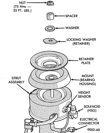
(1)Hold retaining plate locking washer and remove strut rod nut.
(2)Remove locking washer, retainer plate, spacer, flat washer and mount/bearing housing assembly (Fig. 17).
(3)Assemble in reverse order. Hold retainer plate
locking washer with suitable tool and tighten strut rod nut to 75 NIm (55 ft. lbs.) torque.
INSTALLATION
(1)See STRUT DAMPER ASSEMBLY in FRONT SUSPENSION and install strut.
(2)Install solenoid, see: SOLENOIDS (STRUT AND AIR SPRINGS).
(3)Connect electrical leads, solenoid and height sensor.
(4)Charge (inflate) air spring. See RECHARGEAIR SPRING to activate spring solenoid and air compressor. Add air for 60 seconds.
RECHARGE AIR SPRING
To activate compressor; Ground Pin S08 to Pin X20. To Activate Spring Solenoid:
² LF: Ground Pin S31 to X20
Fig. 17 Air Strut Upper Mount Assembly
²RF: Ground Pin S30 to X20
²RR: Ground Pin S32 to X20
AIR SPRINGS REAR
REMOVAL
(1)Disconnect battery negative cable, hoist vehicle and remove wheel and tire assembly.
(2)See AIR LINES AND FITTINGS and disconnect air line and electrical connector from solenoid.
(3)See SOLENOIDS (STRUT AND AIR SPRINGS) and vent air from spring. Remove solenoid.
(4)Release upper air spring alignment/retainer clips. (Fig. 18)
(5)Remove lower spring to axle nut (Fig. 19).
(6)Pry assembly down to pull alignment studs through retaining clips (Fig. 20). Remove assembly.
INSTALLATION
(1)Position assembly lower stud into axle seat and upper alignment pins through frame rail adaptor.
(2)Install upper retaining clips.
(3)Install lower spring to axle nut: LOOSE ASSEMBLE.
(4)Install solenoid and connect air line and electrical connector.
(5)Charge (inflate) air spring. See RECHARGING AIR SPRING and add air for 60 seconds.

Ä
Fig. 18 Release Retaining Clips
Fig. 19 Remove/Install Lower Spring to Axle Nut
Fig. 20 Pry Assembly Out of Retaining Clips
(6)AFTER partial air recharge tighten lower nut to 68 NIm (50 ft. lbs.) torque.
(7)Install wheel and tire assembly. Lower vehicle, install wheel and tire assembly and connect battery negative cable.
SUSPENSION/DRIVESHAFTS 2 - 89
RIGHT SHOCK ABSORBER (WITH HEIGHT SENSOR)
REMOVAL
(1)Disconnect battery negative cable.
(2)Raise vehicle, see Hoisting, Group 0.
(3)Remove tire assembly.
(4)Disconnect height sensor connector located on right rear frame rail.
(5)Remove shock, see Shock Absorbers, Removal.
INSTALLATION
(1)Install shock assembly, see Shock Absorbers, Installation.
(2)Route height sensor wire through retaining clips and then tie strap to fuel filler tube.
(3)Snap height sensor connector into underbody harness connector.
(4)Install wheel/tire assembly.
(5)Height sensor wiring harness and white paint mark on bottom shock eye must face to the front of the vehicle (Fig. 1).
Fig. 1 Right Rear Shock Absorber Installation