

Ä |
|
SUSPENSION/DRIVESHAFTS 2 - 31 |
|
Fig. 20 Install Spring Washer, Nut Lock, & New Cotter Pin
(4) Install wheel and tire assembly. Tighten wheel nuts to 129 NIm (95 ft. lbs.) torque (Figs. 21).
DRIVESHAFT RECONDITIONING PROCEDURE
Driveshaft reconditioning and/or boot replacement for all front wheel drive vehicles is essentially the same per C/V joint.
Note: that lubricant requirements and quantities are different for Inner Joints than for Outer Joints, and type being serviced. Use only the recommended lubricants.
See (Fig. 1) for the exploded view of the front drive shaft components and there location in the assembly.
Fig. 21 Install Wheel And Tire Assembly
Driveshaft requirements are different for various vehicle models, engines, and transaxles, and often change from one model year to the next.
Driveshaft parts will be different to accommodate this. Therefore, when replacing parts, be sure to use only those specified in the service parts catalog. For the exact model year, model, engine, transaxle, and type being serviced.
Fig. 1 Driveshaft Components

2 - 32 SUSPENSION/DRIVESHAFTS |
|
Ä |
|
INNER C/V JOINT
DISASSEMBLE
With the driveshaft removed from the vehicle, identify the unit type (See Fig. 2 under Driveshafts Identification).
(1) Remove the boot clamps and pull back the boot to gain access to the tripod retention system, which prevents accidental separation from the C/V joint housing.
CAUTION: When removing the housing from the tripod, hold the rollers in place on the trunnion studs to prevent the rollers and needle bearings from falling away. After the tripod is out of the housing secure the rollers in place with tape (Fig. 4).
(2) Depending on the type of C/V joint assembly, separate the tripod from the housing as follows:
S.S.G. Utilizes a wire ring tripod retainer which expands into a groove around the top of the housing. Use a flathead screwdriver to pry the wire ring out of the groove and slide the tripod from the housing (Fig. 2). Do not mangle or destroy retainer during disassembly.
Fig. 2 Separate Tripod From Housing S.S.G.
G.K.N. The retention system on this assembly is a integral part of the plastic collar on the inside of the C/V joint housing. Clamp the stub shaft of the C/V joint housing in a vise, use protective caps on jaws of vise to prevent damage to stub shaft. Hold the interconnecting shaft on an angle, while gently pulling on the shaft until one of the tripod bearings is free of the retaining collar. Continue holding the interconnecting shaft on an angle and gently pull on the shaft until all rollers are free of the retaining collar. See (Fig. 3).
Fig. 3 Separate Tripod From Housing G.K.N.
TRIPOD REMOVAL FROM INTERCONNECTING BAR
S.S.G. Remove the snap ring from the shaft end groove. Remove the tripod by hand or by tapping the body with a brass punch (Fig. 4).
Fig. 4 Remove Snap Ring then Tripod
G.K.N. To remove the tripod from the interconnecting bar.
(1) Expand the stop ring behind the tripod and slide it back along the shaft (Fig. 5).

Ä |
|
SUSPENSION/DRIVESHAFTS 2 - 33 |
|
Fig. 5 Removing Stop Ring (G.K.N.)
(2)Slide the tripod back along the shaft, either by hand or by tapping the body with a brass drift. This will expose the circlip on the end of the interconnecting bar.
(3)Remove the circlip from the end of interconnecting bar (Fig. 6).
Fig. 6 Removing Circlip
(4) Remove the tripod from the interconnecting bar. It is not necessary to remove the stop ring from the interconnecting bar unless the bar is being replaced (Fig. 7).
Fig. 7 Tripod Removed From The Interconnecting
Bar
S.S.G. AND G.K.N. WITH SINGLE RING TRIPOD RETENTION.
Remove the tripod assembly to interconnecting shaft retaining snap ring from the interconnecting shaft end groove (Fig. 8). Remove the tripod assembly from the interconnecting shaft by hand or by tapping the body of the tripod assembly with a brass punch (Fig. 9).
Fig. 8 Outer Tripod Retaining Snap Ring Removal
G.K.N. WITH DOUBLE RING TRIPOD RETENTION.
(1)Expand and remove the outer tripod assembly to interconnecting shaft, retaining snap ring (Fig. 10).
(2)Remove the tripod assembly from the interconnecting shaft. Tripod can be removed either by hand or by tapping the tripod body with a brass drift (Fig. 4). Do not hit the outer tripod bearings in an attempt to remove tripod assembly from interconnecting shaft.
(3)Remove the inner tripod assembly to interconnecting shaft, retaining snap ring from the of interconnecting shaft (Fig. 11).
2 - 34 SUSPENSION/DRIVESHAFTS |
|
Ä |
|
components for EXCESSIVE wear and replace if necessary.
Inspect the spring, spring cup, and the spherical end of the connecting shaft for EXCESSIVE wear or damage and replace, if necessary.
ASSEMBLE C/V JOINT
TRIPOD ASSEMBLY INSTALLATION G.K.N.
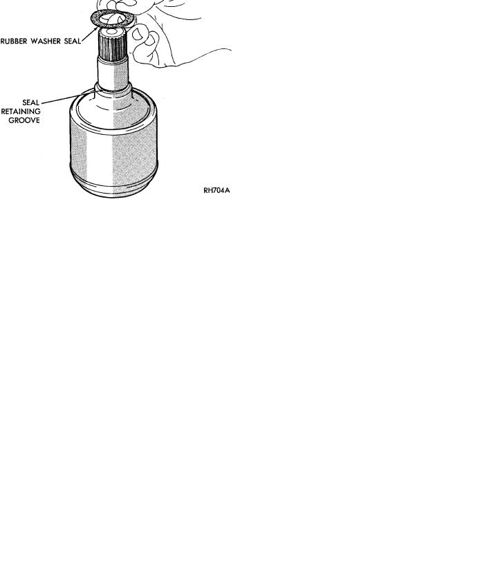
(1) Slide rubber washer seal over stub shaft and down into the groove provided (Fig. 12). The rubber washer seal is used only on the right inner C/V joint on the Equal Length Drive Shaft Systems.
Fig. 9 Tripod Assembly Removal From
Interconnecting Shaft
Fig. 10 Removing Outer Tripod Retaining Snap Ring
(G.K.N.)
Fig. 11 Removing Inner Tripod Retaining Snap Ring
(G.K.N.)
INSPECT TRIPOD AND HOUSING
Remove as much grease as possible from assembly and inspect joint housing ball raceway and tripod
Fig. 12 Rubber Washer Seal Installation
(2)Fasten the (new) boot to the interconnecting shaft. See Boots Install.
(3)Slide the stop ring back into the stop ring groove on the interconnecting bar (Fig. 5).
(4)Install a new circlip in the circlip groove on the interconnecting bar (Fig. 6).
(5)With the chamfered end (Fig. 13 & 14 ) of the tripod facing the stop ring. Align the tripod splines and push or tap on the body of the tripod assembly with a SOFT drift, until tripod is seated on the shaft.Check to make sure that the Tripod is Engaged by attempting to pull the tripod off of the shaft by hand.
TRIPOD ASSEMBLY INSTALLATION S.S.G.
(1)Slide rubber washer seal over stub shaft and down into the groove provided (Fig. 12). The rubber washer seal is used only on the right inner C/V joint on the Equal Length Drive Shaft Systems.
(2)Fasten the (new) boot to the interconnecting shaft. See Boots Install.
(3)Install first wire ring tripod retainer over interconnecting shaft, slide tripod on the shaft, both ends are the same (Fig. 15).

Ä |
|
SUSPENSION/DRIVESHAFTS 2 - 35 |
|
Fig. 13 G.K.N. Tripod Thick Ring Side
Fig. 14 G.K.N. Tripod Circlip Side
(4) Install the snap ring into the groove on the interconnecting shaft to lock the tripod in position (Fig. 16)
Should the wire ring tripod retainer not be suitable for reuse or a new one is not available,the following procedure should be used:
(1)Install tripod on the shaft.
(2)Install spring and cup assembly into inner joint housing.
(3)Position small end of boot in locating grooves on the interconnecting shaft.
Fig. 15 Tripod Snap Ring Installation
Fig. 16 Tripod Installation
(4)Clamp the small end boot clamp onto boot, retaining boot to the interconnecting shaft.
(5)Distribute 1/2 packet of grease into boot and 1/2 into housing.
(6)Install tripod into housing.
(7)Place large clamp over shaft.
(8)Install driveshaft into vehicle, see Driveshaft Install.
(9)Position large end of boot into locating groove.
(10)Slide large clamp into position.
(11)See Boot Install for clamping instructions.
TRIPOD ASSEMBLY INSTALLATION S.S.G. & G.K.N. WITH SINGLE RING RETENTION
(1)Fasten the (new) boot to the interconnecting shaft. See Boots Install.
(2)Install the tripod assembly onto the interconnecting shaft until it is past the snap ring groove on the shaft (Fig. 17). If required the tripod assembly can be tapped onto the interconnecting shaft using a brass drift, on the body of the tripod assembly (Fig. 4). Do not hit the outer tripod assembly bearings in an attempt to install tripod on interconnecting shaft.

2 - 36 SUSPENSION/DRIVESHAFTS
Fig. 17 Interconnecting Shaft Snap Ring Groove
(3) Install a NEW outer tripod assembly to interconnecting shaft retaining snap ring, into the interconnecting shaft snap ring groove (Fig. 18). Be sure that the snap ring is fully seated into the snap ring groove around the entire interconnecting shaft.
Fig. 18 Outer Tripod Retaining Snap Ring Installa-
tion
TRIPOD ASSEMBLY INSTALLATION G.K.N. WITH DOUBLE RING RETENTION
(1)Fasten the (new) boot to the interconnecting shaft. See Boots Install.
(2)Install the inner tripod assembly retaining snap ring into the retaining groove on the interconnecting shaft (Fig. 19).
(3)Install the tripod assembly onto the interconnecting shaft until it is past the outer snap ring groove on the shaft (Fig. 17). If required the tripod assembly can be tapped onto the interconnecting shaft using a brass drift, on the body of the tripod assembly (Fig. 4). Do not hit the outer tripod assembly bearings in an attempt to install tripod on interconnecting shaft.
Ä
Fig. 19 Inner Snap Ring Installation
(4) Install the outer tripod assembly to intermediate shaft retaining snap ring into the snap ring groove on the intermediate shaft (Fig. 20).
Fig. 20 Outer Snap Ring Installation
INNER C/V JOINT HOUSING INSTALLATION
G.K.N.
(1)Distribute 1/2 the amount of the grease provided into the housing and the remaining amount into the boot.
(2)Position the spring in the housing spring pocket with the spring cup attached to the exposed end of the spring (Fig. 21). Place a small amount of grease on the concave surface of the spring cup.
CAUTION: Care must be taken to ensure proper spring positioning. The spring must remain centered in the housing spring pocket when the tripod is installed and seated in the spring cup (Fig. 13).
(3) Clamp the stub shaft of the housing in a vise.
Use protective caps on jaws of vise so stub shaft does not get damaged by the vise. Position the interconnecting shaft and the tripod assembly on top of