

Part IV - Well productivity estimating methods
.pdfInflow Control Valves
Inflow Control Valves can be classified according to the following attributes:
Number of positions they can take:
Two-point ICV, enable to take only two positions (“on/off”);
Multipoint ICV (6-11 positions), (Fig. on the left)
Infinite point ICV (Fig on the right)
Type of control system:
Hydraulic (for two-point and multipoint ICV)
Electric (for infinite-point ICV)
Combined (for all types)
15 September 2012 |
51 |
Prepared by Alexey Khrulenko, 2010

High Technology Wells.
Main manufacturers and geography of deployment
Main manufacturers of high technology assembly (SPE 106011, 2006):
WellDynamics (Haliburton’s division) ~50% of market
Baker Hughes and Schlumberger - 20-25% each
The rest is split between BJ Services, Weatherford and others
Main regions of use :
North Sea and Norwegian Continental Shelf;
GOM;
Shelves of Bruney and Malaisya;
Offshore / onshore fields on the Persian Gulf countries;
Shelf of Nigeria;
Shelf of Brasil
15 September 2012 |
52 |
Prepared by Alexey Khrulenko, 2010

Tasks that can be solved by means of «Smart Wells»
1.Optimal production from several reservoirs
2.Control of injection to several reservoirs
3.Drainage of several oil zones in separate reservoirs
4.Production from oil rims
5.Intrawell gas lift
6.Variable gas production
7.Inflow control from several boreholes of a multibranch well
8.Increase of sweep efficiency in a system of producing and injection wells
9.Etc.
+ combinations of the above tasks
15 September 2012 |
53 |
Prepared by Alexey Khrulenko, 2010 |
|
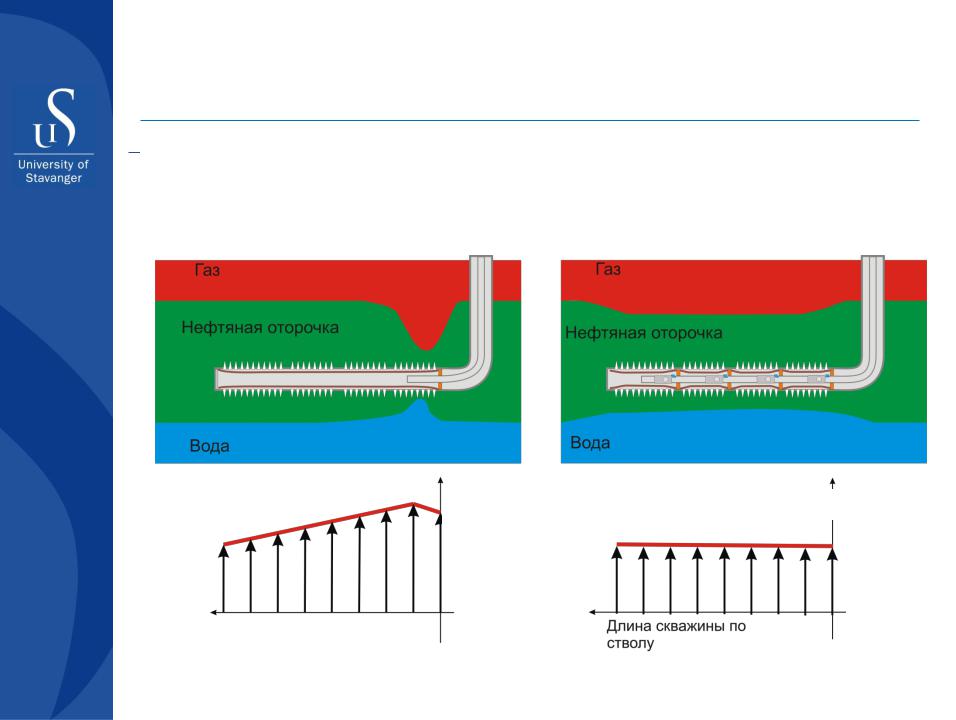
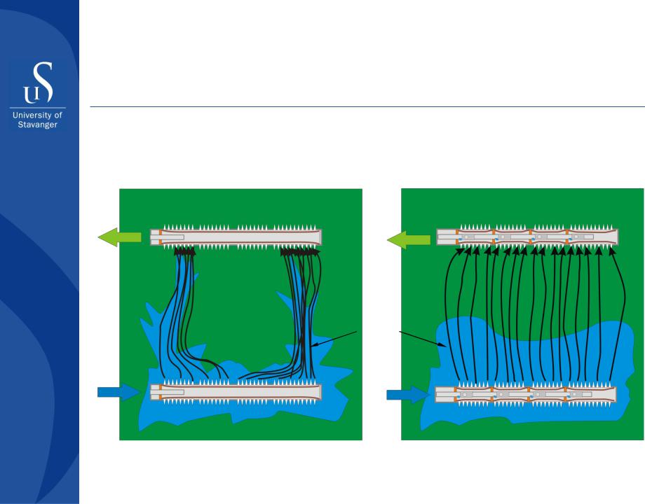
Production from oil rims
Inflow profile to (a) conventional HW and (b) High Technology Well
In (a) well inflow profile distributed unevenly because of pressure drop along the well. As a result, earlier water and gas breakthrough in the heel region. In case (b) inflow profile is equalized.
a) |
|
|
Gas |
b) |
|
|
Gas |
|
|
|
|
||||
|
|
|
|
|
|
||
|
|
|
|
|
|
|
|
|
|
Oil rim |
|
|
|
|
|
|
|
|
|
Oil rim |
|||
|
|
|
|
|
|
|
|
|
Water |
|
Water |
|
|
|
|
Pressure drop
Pressure drop
Well length |
Well length |
|
15 September 2012 |
|
54 |
|
Prepared by Alexey Khrulenko, 2010
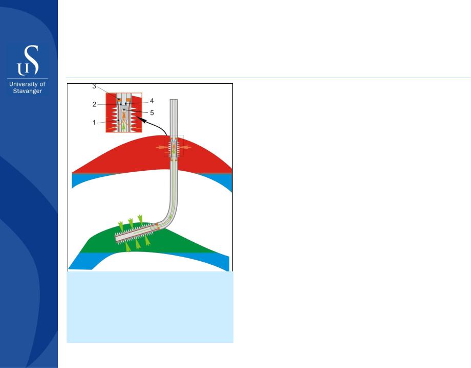
Intrawell gas lift
1.Gravel pack.
2.Pressure and temperature sensors on the outer side of production tubing;
3.Packers;
4.Pressure and temperature sensors on the inner side of production tubing;
5.ICV controlling gas rate to production tubing
15 September 2012
Energy of gas cap is used to lift the oil
Examples of application:
Troll (Norsk Hydro, North Sea) – optimization of production from the oil rim
Abqaiq (Saudi Aramco) – securing the well flowing with high watercut
Fram Vest (Norsk Hydro, North Sea) – managing high well head pressure for increased oil production
Norne (Statoil, North Sea) – securing the subsea well flowing as an alternative to ESP or conventional gas lift application
Egret (Shell, Bruney shelf) – same + managing high well head pressure for stable transport of oil from subsea asset to a stationary platform
55
Prepared by Alexey Khrulenko, 2010
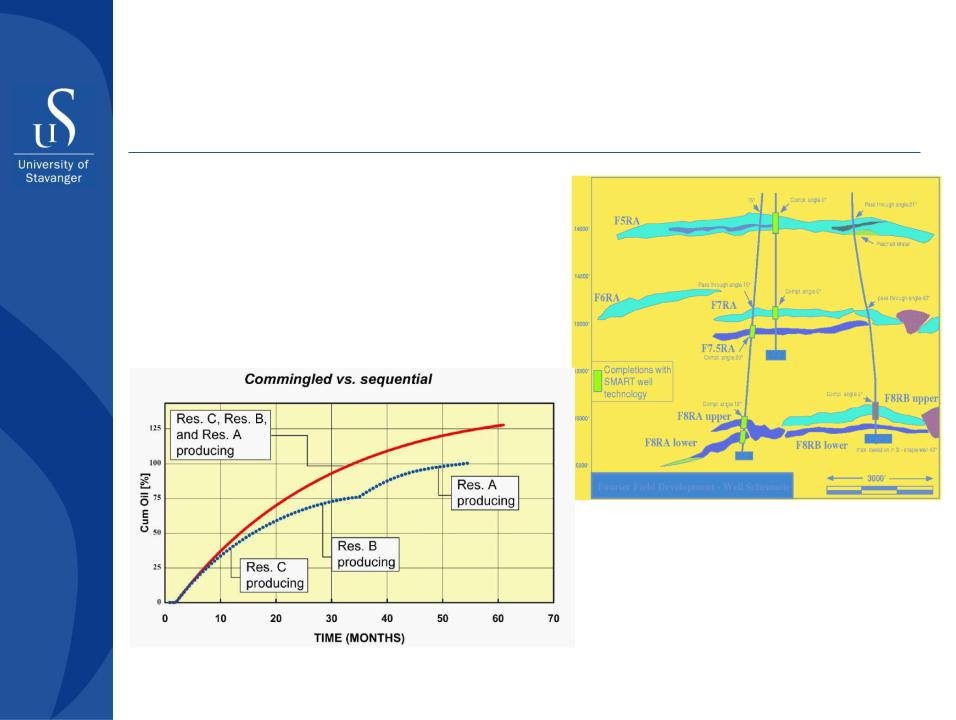
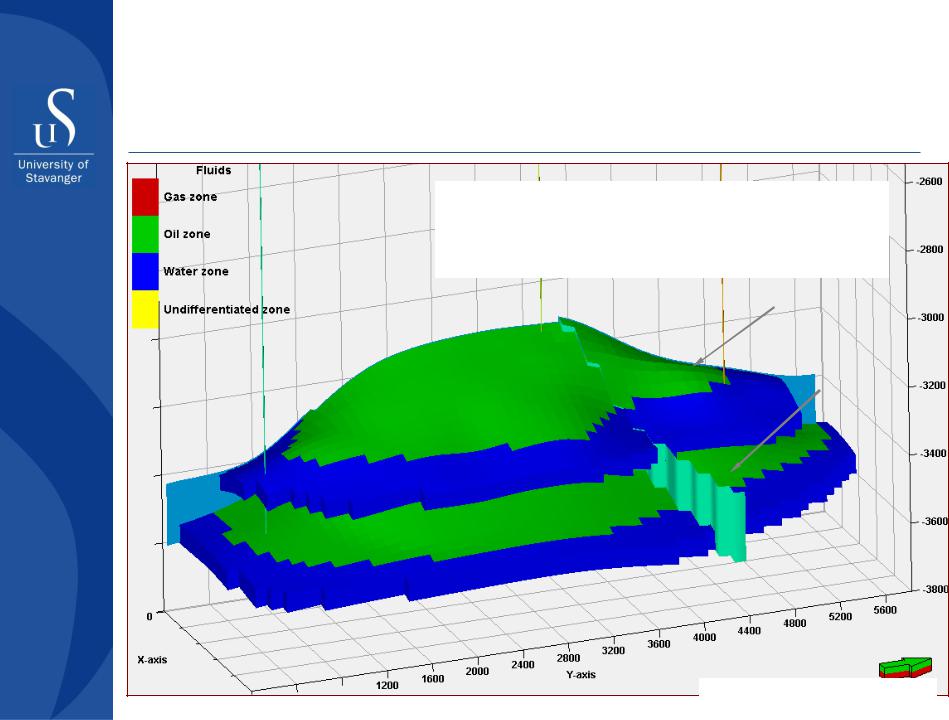
HTW: commingled production from 3 reservoirs, Na-Kika field, GOM
Vertical cross-section
Fourie field, Na-Kika project
Plots of cumulative oil production for commingled (red) and sequential (blue) production scenarios
15 September 2012 |
56 |
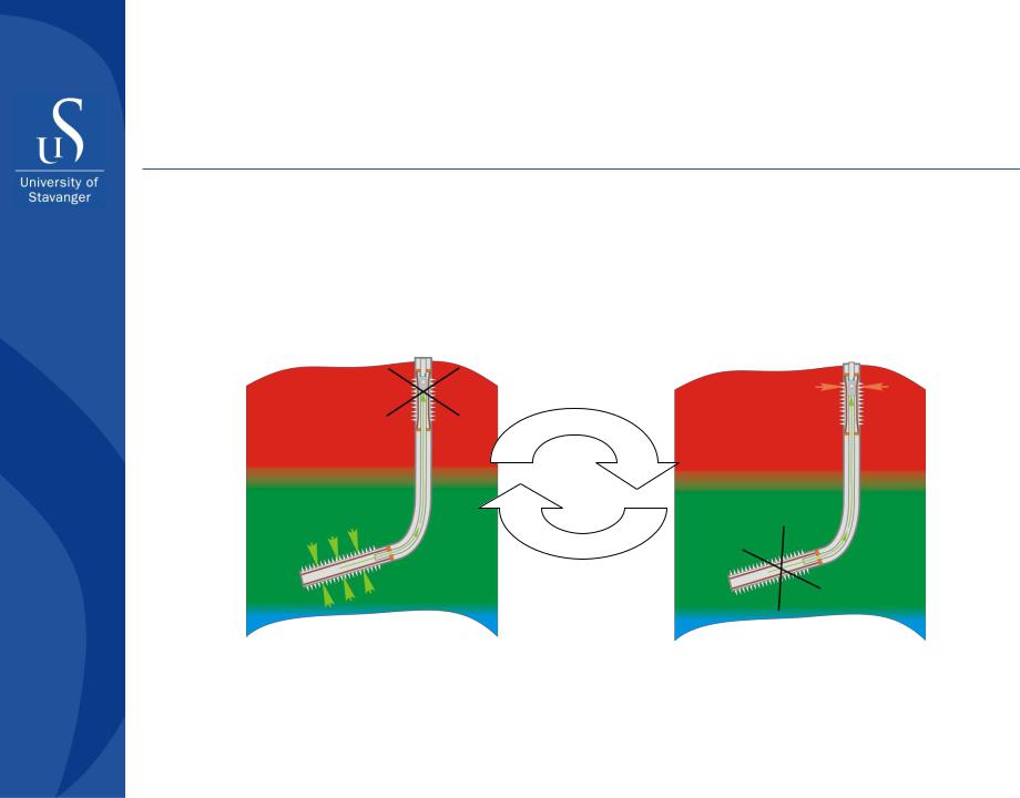
Alternating gas production
Layout is similar to that for intrawell gas lift. Used for securing increased gas production rates if required for a higher consumption. In this case deliverability of ICV to control production from the gas interval should be higher than required for the intrawell gas lift.
Oil production. Gas interval shut in |
Gas production. Oil interval shut in |
Examples of |
|
Vestflanken (Norsk Hydro, North Sea) |
application: |
|
Brent Charlie (Shell, North Sea) |
15 September 2012 |
57 |
•Prepared by Alexey Khrulenko, 2010 |
|
Improving sweep efficiency in a system of injection and production wells
Displacement of oil by water in
heterogeneous reservoir by means Same + application of ICV of horizontal injector and producer
Producer |
Producer |
Stream
lines
Injector |
Injector |
Prepared by Alexey Khrulenko, 2010 |
58 |
15 September 2012 |
Example
•59
•Prepared by Alexey Khrulenko, 2011
Problem setup
Oil viscosity μo=0,55 cp; |
Water viscosity μw= 0,3 cp; |
Bubble point pressure Psat=245 bar; |
Solution GOR R =100 m3/m3 |
s |
10,65 million m3 |
330 bar |
352.5 bar |
25,1 million m3 |
Prepared by Alexey Khrulenko, 2011 |