

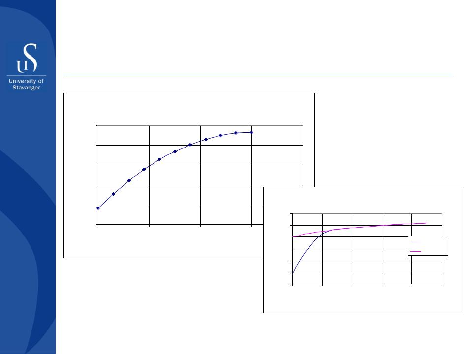
Discounted effect, ICVs performance
|
|
500 |
|
|
|
|
|
|
Дисконтированный•Discounted effect, $эффектmillion , |
|
400 |
|
|
|
|
|
|
|
300 |
|
|
|
|
|
|
|
млн. $ |
200 |
|
|
|
|
|
|
|
100 |
|
|
|
|
|
|
||
0 |
|
|
|
|
|
|
||
|
|
0 |
5 |
10 |
15 |
20 |
25 |
|
|
|
-100 |
|
|
|
|
|
|
|
|
|
|
• |
|
Time, years |
|
|
|
|
|
|
|
Время, лет |
|
|
|
•Prepared by Alexey Khrulenko, 2011
Part II - Well completion design |
#5 |
|||
#1 |
#2 |
#3 |
#4 |
|
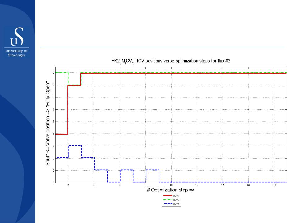
Position of ICV in one of the wells
•Prepared by Alexey Khrulenko, 2011

Section 2
Well perforation
Part II - Well completion design

Well perforation
Perforation technique
Perforation design
Evaluating efficiency of perforation
−Depth of penetration
−Shot density
−Phasing
Part II - Well completion design
Well Perforation
Liner
Part II - Well completion design
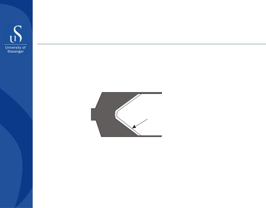
Well Perforation
Unfired shaped charge
Liner
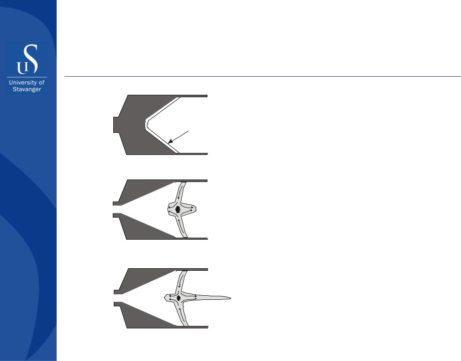
Charge detonates.
Liner begins to collapse
High pressure jet forms.
Pressure wave with p=500000 bar travels at9000 km/hour
Part II - Well completion design
Well Perforation
Plasma jet
Jet becomes more developed. Pressure causes jet velocity to increase to 25000 km/hour
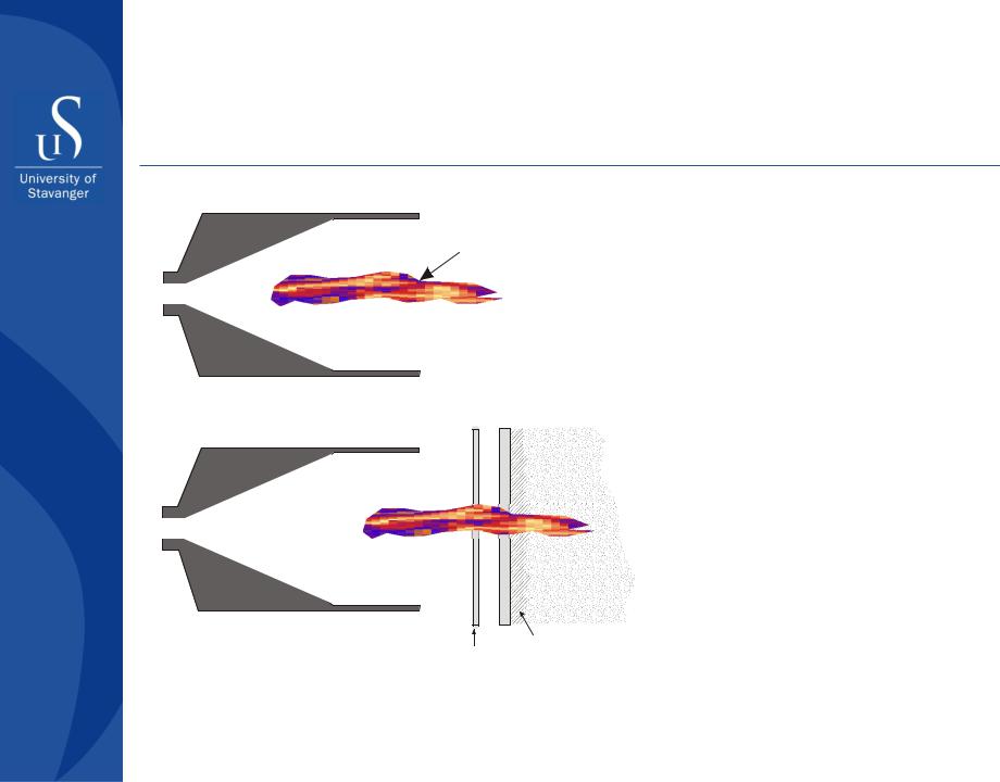
Jet is fully formed.
Tip of jet pierces and compacts the casing, cement, and formation
with 350000 bar
Formation
Hollow  Cement carrier Casing
Part II - Well completion design

Well Perforation
Perforation performance depends on a number of factors, among which most important are:
Charge type
Gun size
Shot density
Phasing
Conveyance method
Wellbore fluids
Part II - Well completion design

Well Perforation
Perforation cleaning
Failure to remove debris and compacted zone can reduce the potential productivity of a well as much as 80%!
The following methods can be used for perforation cleaning:
Acidizing
Washing
Backsurging
Underbalance perforating
Part II - Well completion design

Well Perforation
Perforation design
Important parameters of perforation design are:
Shot density
Shot phasing
Depth of perforation
Part II - Well completion design
Well Perforation
Perforation design
Part II - Well completion design
Well Perforation
|
Pressure distribution along the perforation tunnel |
|
|
|
|
|
|
|||||
|
175 |
|
|
|
|
|
|
|
|
|
|
|
|
170 |
|
|
|
|
|
|
|
|
|
|
|
bar |
165 |
|
|
|
|
|
|
|
|
|
|
pe=200 bar |
Pressure, |
|
|
|
|
|
|
|
|
|
|
||
|
|
|
|
|
|
|
|
|
|
|
||
160 |
|
|
|
|
|
|
|
|
|
|
|
|
155 |
|
|
|
|
|
|
Pressure distribution within drainage area |
|||||
|
|
|
|
|
|
|
|
|
|
|
|
|
|
|
|
|
|
|
180 |
|
|
|
|
|
|
|
150 |
|
|
|
bar |
175 |
|
|
|
|
|
|
|
0,00 |
0,05 |
0,10 |
0,15 |
170 |
0,20 |
|
|
|
Real well |
||
|
|
Length of perforation tunnel, cm |
Pressure, |
165 |
|
|
|
|
|
|||
|
|
|
|
|
|
|
Ideal well |
|||||
|
|
|
|
|
|
|
|
|
|
|||
|
|
|
|
|
|
|
|
|
|
|
||
|
|
|
|
|
160 |
|
|
|
|
|
|
|
|
|
|
|
|
|
|
|
|
|
|
|
|
|
|
|
|
|
|
155 |
|
|
|
|
|
|
|
|
|
|
|
|
150 |
|
|
|
|
|
|
|
|
|
|
|
|
0,10 |
0,20 |
0,30 |
0,40 |
0,50 |
0,60 |
|
|
|
|
|
|
|
|
|
|
Distance from wellbore, m |
|
|
|
Part II - Well completion design