

Erosion risk management
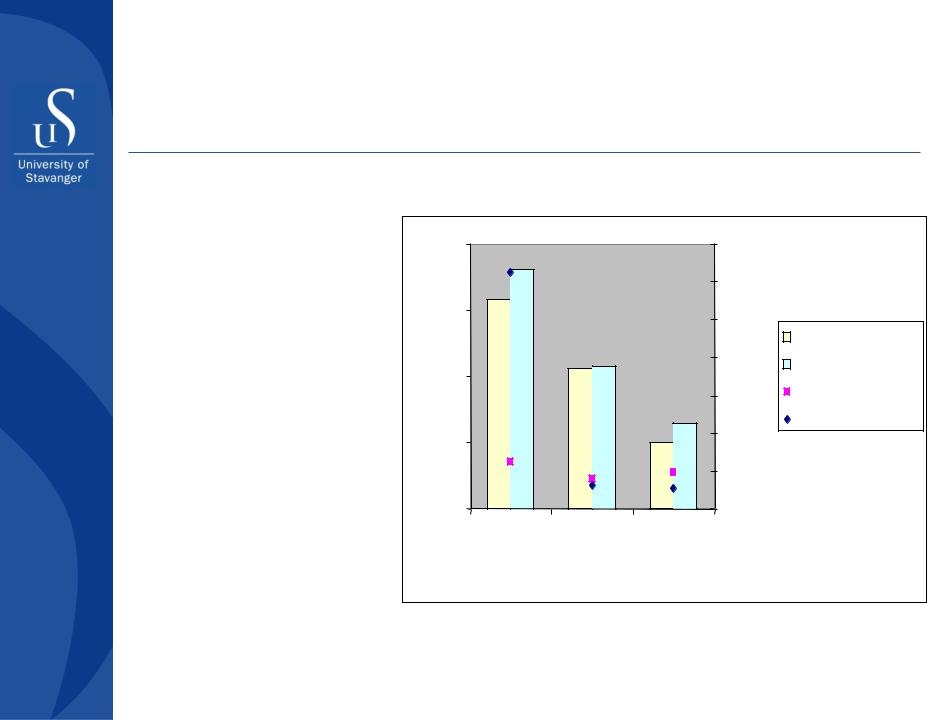
Examples of developing materials with improved erosion resistance
Choice of correct material in critical wear parts can increase the life by a factor of 10100.
|
100 |
|
140 |
|
|
rateErosion[mm3/kg] |
|
|
120 |
|
|
10 |
|
|
Hardness/ Toughness |
|
|
|
|
|
100 |
WS 90/90 |
|
|
1 |
|
80 |
|
WS 90/30 |
|
|
60 |
|
Hardness |
|
|
|
|
|
||
|
|
|
40 |
|
Toughness |
|
0,1 |
|
|
|
|
|
|
|
|
|
|
|
|
|
20 |
|
|
|
0,01Stainless |
Traditional |
0 |
|
|
|
steel 316L |
Improved TC- |
|
||
|
TC-material |
material |
|
|
|
Part II - Well completion design
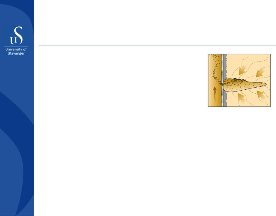
Sand management
Focus areas
 High quality data acquisition
Sand production prediction to evaluate need for sand control
Open hole solution for sand control to limit production impairment
Erosion risk management
Top side sand handling and disposal according to regulations
Part II - Well completion design

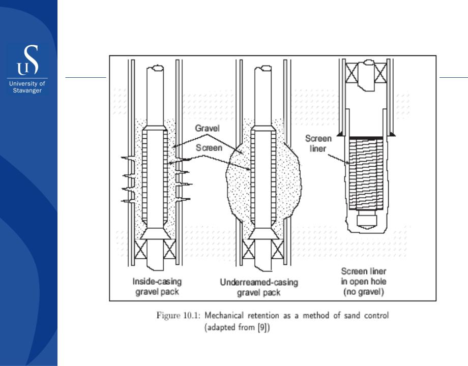
Gravel packing
Part II - Well completion design
Gravel packing
Part II - Well completion design
Gravel packing
Part II - Well completion design

Gravel packing
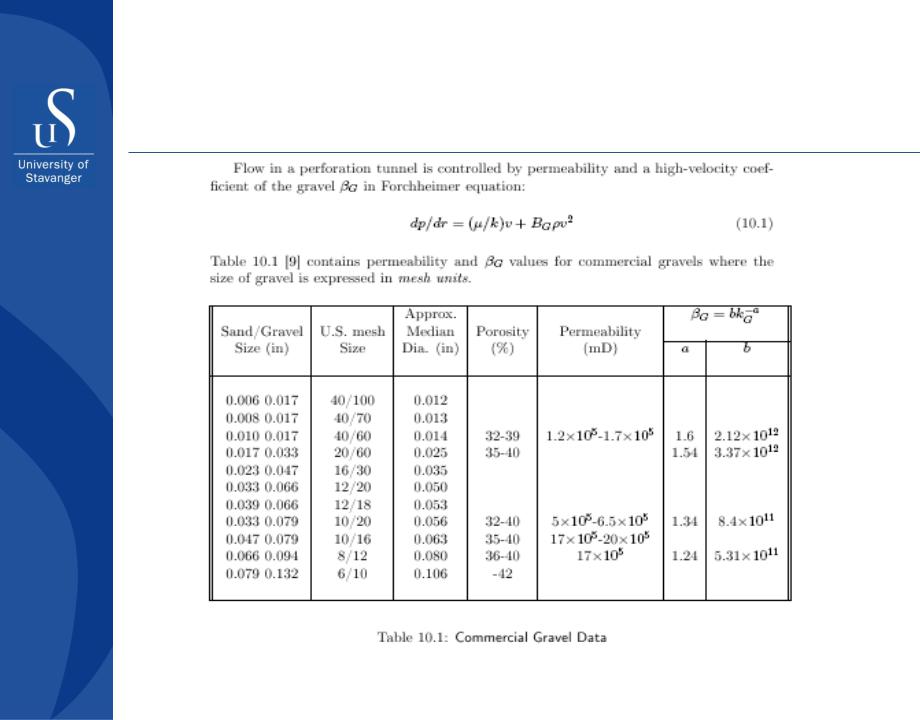
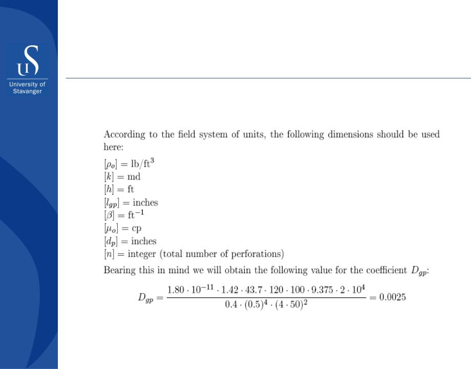
Mesh = number of openings per inch, counting from the center of any wire in the sieve to a point exactly 1 inch distant. Mesh sizes are read as follows: 20/40 mesh commercial gravel passes through a 20-mesh sieve and is retained by a 40-mesh sieve.
20/40 commercial gravel has permeability kg approx 120 D and bg = 30000 1/ft
Part II - Well completion design

Gravel packing
Productivity of a well: |
qo = |
|
|
2πkh∆p |
|
|
|||||||
|
|
|
|
|
|
|
|
||||||
|
|
|
|
|
|
|
|||||||
|
|
|
|
|
|
|
|
|
|
re |
|
|
|
|
|
|
|
|
|
|
|
|
|||||
|
|
|
|
|
|
µo Bo ln r |
|
+Stot |
|
||||
|
|
|
|
|
|
|
|
|
w |
|
|
|
|
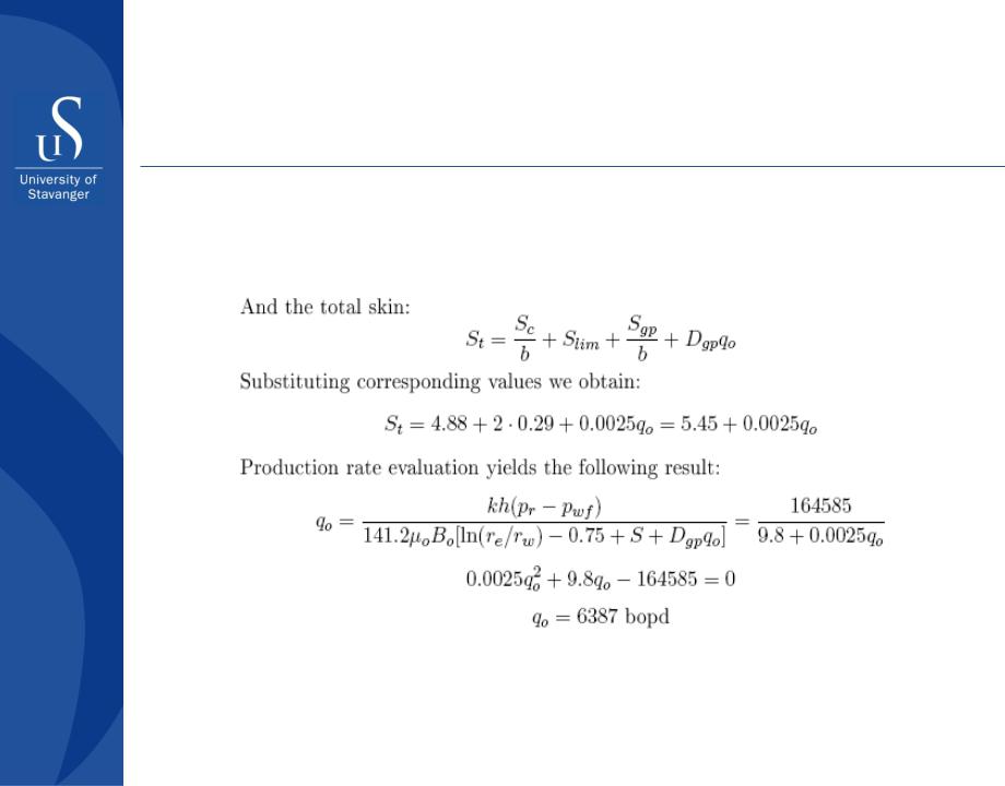
Total skin: |
Stot |
=...+ |
|
S gp |
+Dgp qo |
|
|
|
|||||
|
|
b |
|
|
|
||||||||
|
|
|
|
|
|
|
|
|
|
|
|
|
|
Linear term: |
S gp =. |
|
2πklgp |
|
|
|
|
|
|
||||
kgp |
ns Ap |
|
|
|
|
|
|
||||||
|
|
|
|
|
|
|
|
|
|||||
Non-linear term: Dgp =1.80 10−11 Bo ρokhlgp βg
µod p 4n2
Part II - Well completion design
Gravel packing
According to the Forcheimer equation the high velocity flow effect can be calculated as follows:
for gas wells:
D gp = 2.45 10−13 |
γ g khL p |
|
βg |
||||
µg d p 4n2 |
|||||||
|
|
|
|
|
|||
for oil wells: |
|
|
|
|
|
|
|
D gp =1.80 |
10 |
−11 |
Bo ρokhL p |
βg |
|||
|
|
µod p 4n2 |
|||||
|
|
|
|
|
|||
Part II - Well completion design

Gravel packing
Evaluation of βg-values
Cooke (1973): |
βg =b kg −a |
|
||
Geertsma (1974): |
|
|
|
|
dry gravel: |
βg =1.746 107 k g −0.5 φ−1.5 |
|||
wet gravel: |
βg = |
1.746 107 |
kg +0.5 φ−1.5 |
|
krg 0.5 |
(1−Sw )1.5 |
|||
|
|
|||
Jones and Owens (1980): |
β = 0.86 kl −0.33 |
|||
Zolotukhin (2001): |
β = λ2/3 φ1/3 kl −1/3 |
|||
λ – free pass of gas molecules at standard conditions
Part II - Well completion design

Gravel packing
The essentials involved in designing the gravel flow pack are:
Analyzing the production formation
Assertaining the gravel-to-sand ratio
Determining formation sand uniformity, and
Estimating the velocity through the slots
Part II - Well completion design
Gravel packing
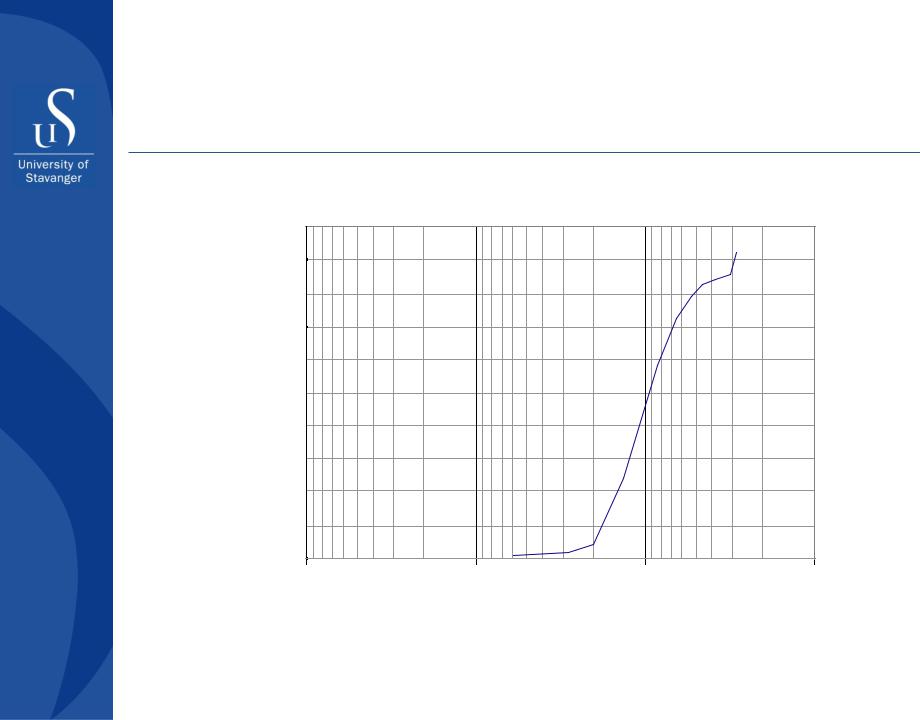
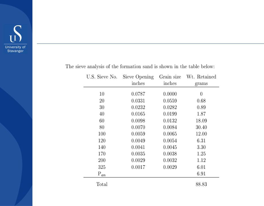
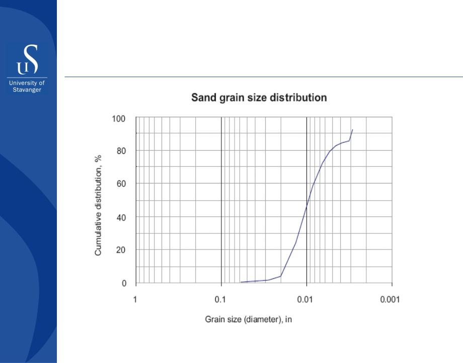
Sieve analysis of the formation sand and grain size distribution
Sand grain size distribution
100
Cumulative distribution, %
80
60
40
20
0
1 |
0.1 |
0.01 |
0.001 |
Grain size (diameter), in
Part II - Well completion design

Design of gravel pack
Analysis of producing formation
−For correct gravel sizing, the producing formation’s grain size must be determined accurately!
−A representative sample is extracted, dried, weighed, separated and passed through screens of varying sizes, from the largest to the smallest screen.
−The material on each screen is weighed and a plot of the grain size distribution is constructed
Part II - Well completion design

Design of gravel pack
Analysis of producing formation (cont-d)
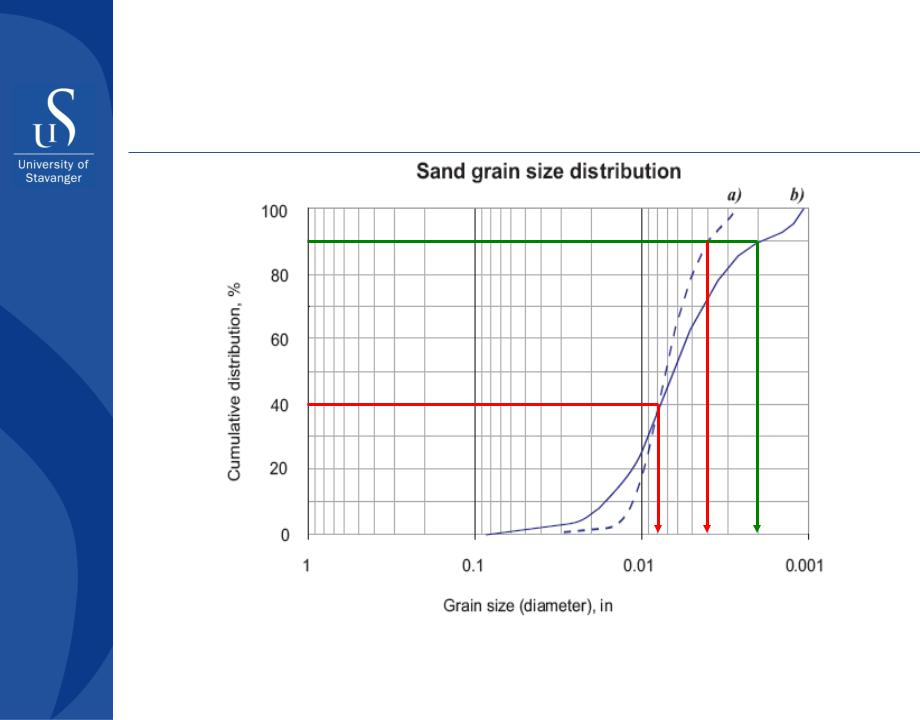
−The slope of the curve is a measure of the sand’s uniformity.
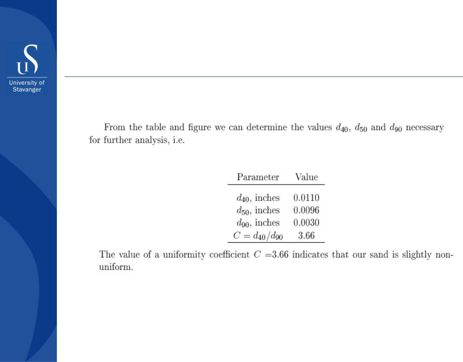
−A uniformity coefficient C is determined from the
following equation: C=d40/d90, where d40 is the grain diameter at 40 percentile point and d90 – at 90 percentile point
−C<3 describes a uniform sand
−C>5 – a non-uniform sand
Part II - Well completion design

Design of gravel pack
Gravel-to-sand ratio (GSR) – a ratio of the gravel grain
size to the formation grain size
−GSR < 4 produce a table pack but impairs productivity
−GSR > 10 – formation invades the pack and reduce permeability
−GSR of 5-6 is optimal (Cgp = 1.5 – 2)
Grain selection
−Quality for gravel: roundness and sphericity > 0.7
Gravel pack thickness
−The ideal GP thickness is not less than 6 inches
Part II - Well completion design
Design of gravel pack
Example of uniform and non-uniform grain size distributions
Ca=0.008/0.004 = 2; Cb = 0.008/0.002 = 4
Part II - Well completion design

Design of gravel pack
Sand uniformity coefficient
C= d40 d90
A C ratio less than 3 describes a uniform sand while a C ratio greater than 5 describes a non-uniform sand
Part II - Well completion design

Design of gravel pack
Gravel-to-Sand ratio:
GSR = D50
d50
Gravel-to-Sand ratio is the most important parameter used to design a gravel flow pack
GSR should be > 4 and < 10
An optimum value GSR = 6
Part II - Well completion design
Design of gravel pack
Cumulative distribution, %
Sand grain and gravel size distribution
100
80
60
40
20
0
1 |
0.1 |
0.01 |
0.001 |
Grain size (diameter), in
Part II - Well completion design
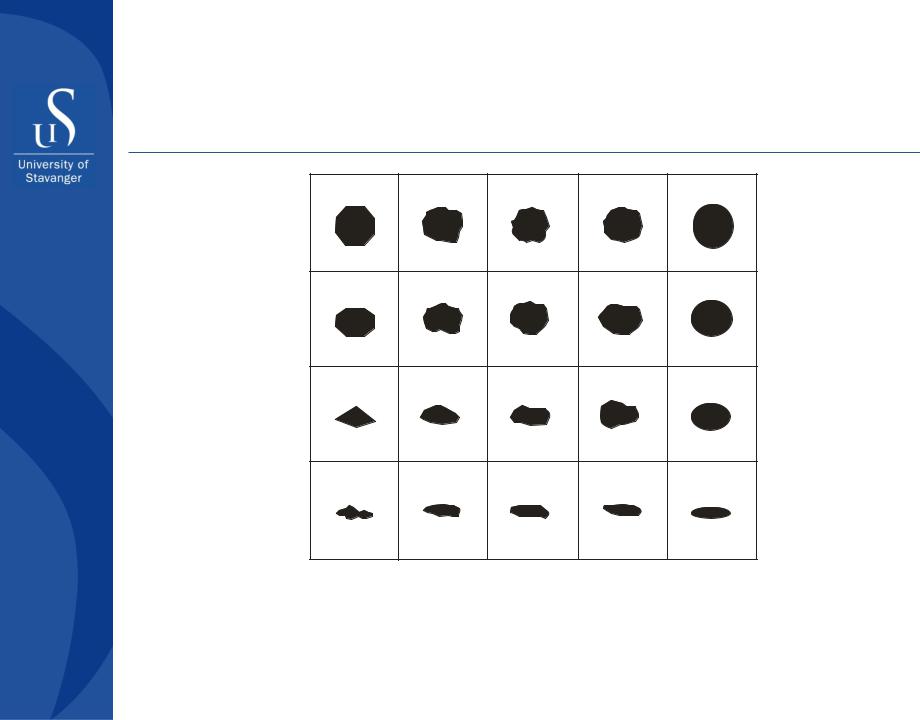
Gravel Selection
Sphericity
0.9
0.7
0.5
0.3
0.1 |
0.3 |
0.5 |
0.7 |
0.9 |
Roundness
Part II - Well completion design
Gravel packing
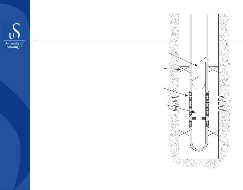
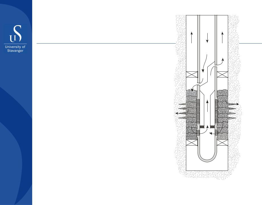
Vertical well with installed tools for gravel packing
Crossover
Crossover
packer
Screen
Wash pipe
Part II - Well completion design
Gravel packing
Flow paths and the packing sequence in a vertical well
Part II - Well completion design
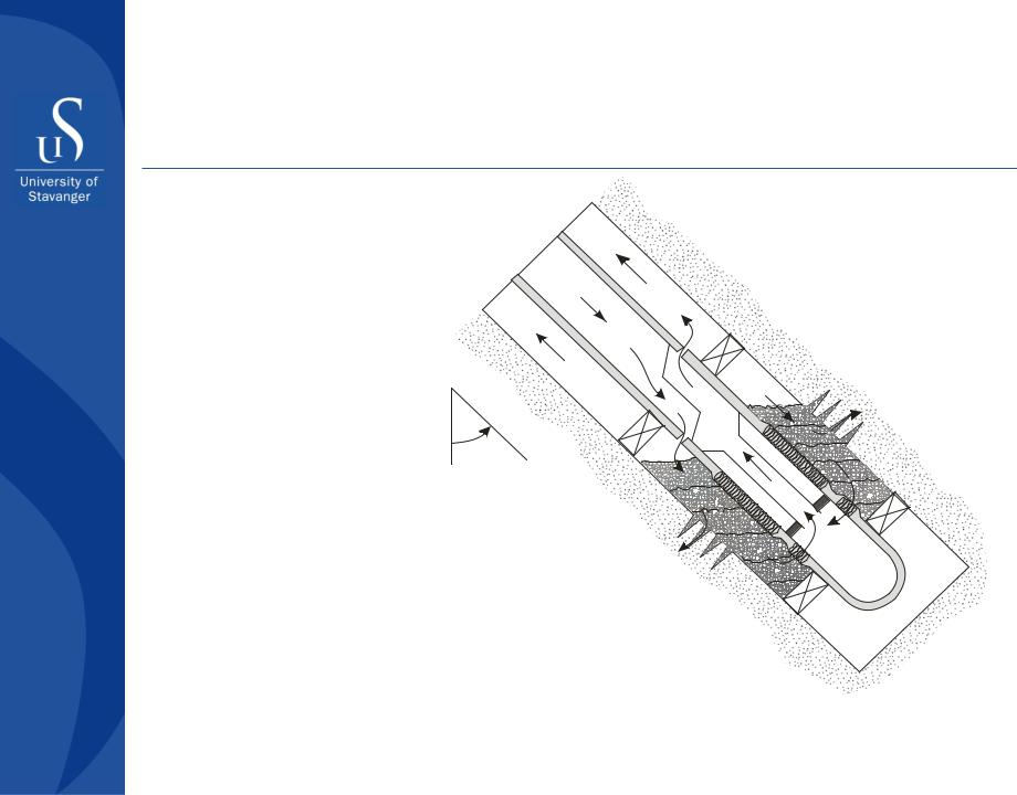
Gravel packing
450
Flow paths and the sequence in a deviated
Part II - Well completion design
Gravel packing
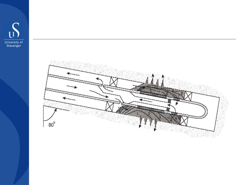
Flow paths and the packing sequence in a high angle deviated or horizontal well.
The numbers show the order of gravel pack placement. Numbers from 1 to 7 correspond to the alpha-wave, while numbers from 8 to 11 indicate the beta-wave.
Part II - Well completion design
Gravel packing
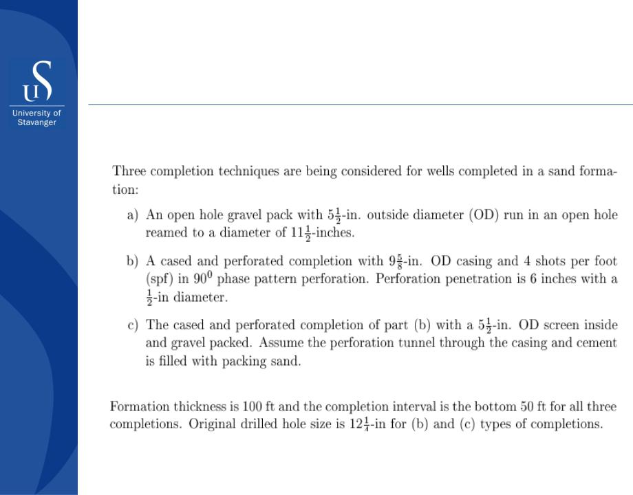
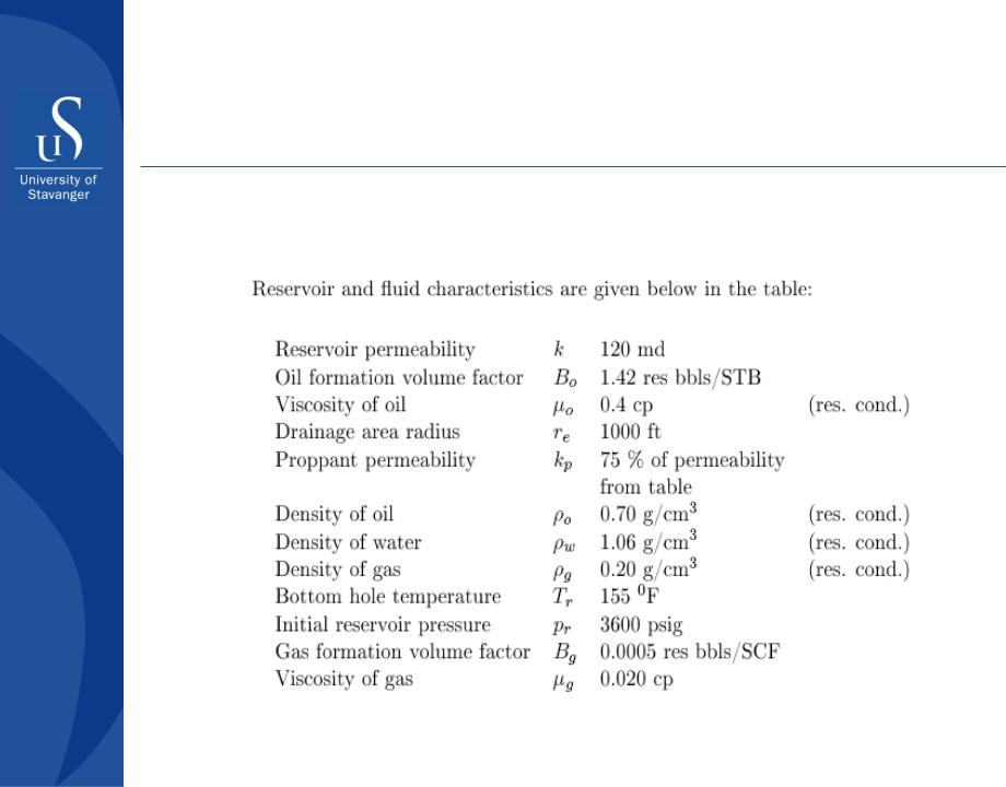
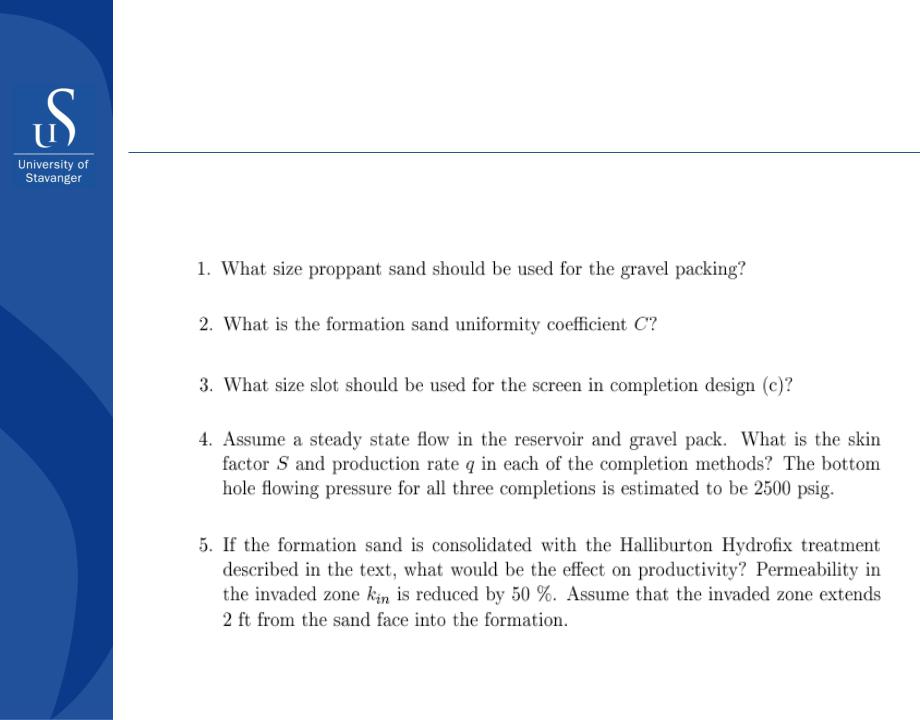
Exercise (compendium, p. 193)
Part II - Well completion design
Gravel packing
Exercise
Part II - Well completion design
Gravel packing
Exercise
Part II - Well completion design
Gravel packing
Exercise
Part II - Well completion design
Gravel packing
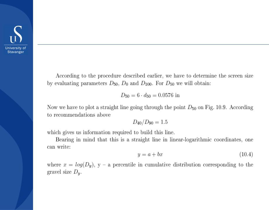
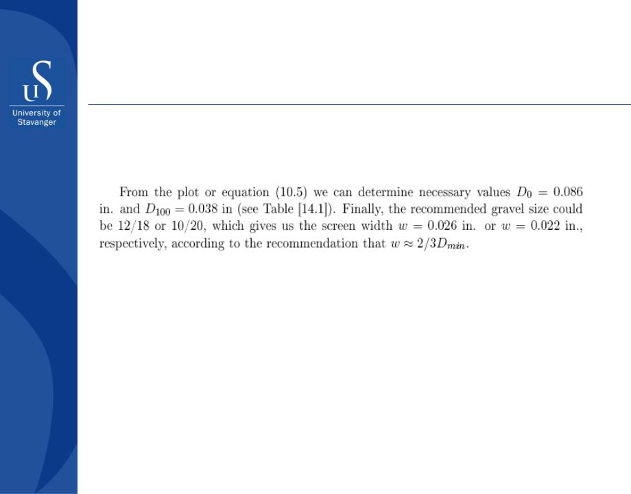
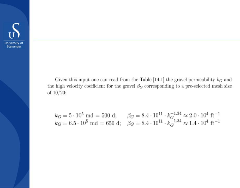
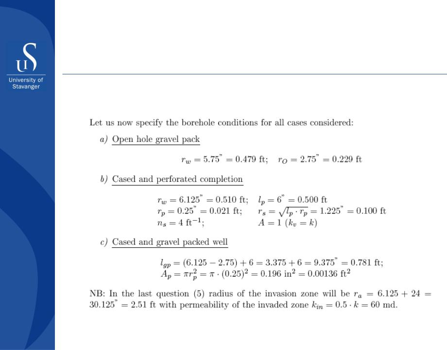
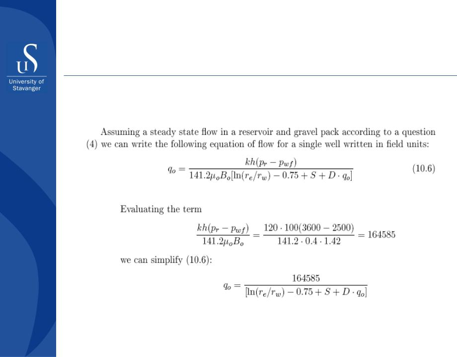
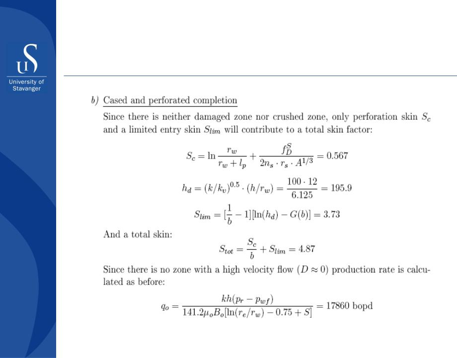
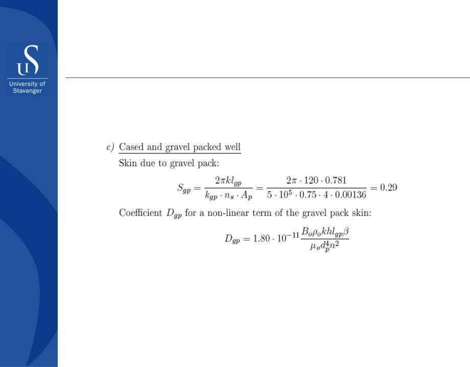
Solution to Exercise
Part II - Well completion design
Gravel packing
Solution to Exercise
Part II - Well completion design
Gravel packing
Solution to Exercise
Part II - Well completion design
Gravel packing
Solution to Exercise
Part II - Well completion design

Gravel packing
Solution to Exercise
Part II - Well completion design

Gravel packing
Solution to Exercise
Part II - Well completion design
Gravel packing
Solution to Exercise
Part II - Well completion design
Gravel packing
Solution to Exercise
Part II - Well completion design
Gravel packing
Solution to Exercise
Part II - Well completion design
Gravel packing
Solution to Exercise
Part II - Well completion design
Gravel packing
Solution to Exercise
Part II - Well completion design
Gravel packing
Solution to Exercise
Part II - Well completion design
Gravel packing
Solution to Exercise
Part II - Well completion design
Gravel packing
Solution to Exercise
Part II - Well completion design
Gravel packing
Solution to Exercise
Part II - Well completion design
Gravel packing
Solution to Exercise
Part II - Well completion design
Gravel packing
Solution to Exercise
Part II - Well completion design