

Saving a Run Under a New Name
Before creating a new run, create and save a copy of Solid2 with a new Run ID, Solid3. Then you can make modifications under this new Run ID.
1From the Aspen Plus menu bar, select File | Save As.
2In the Save As dialog box, choose the directory where you want to save the simulation.
3In the File name field, enter Solid3.
4In the Save as type field, click  and select Aspen Plus Documents (*.apw).
5Click Save to save the simulation and continue.
Aspen Plus creates a new simulation model, Solid3, which is a copy of the base case simulation, Solid2.
4-4 • Modeling Gas-Solid Separators |
Getting Started - Solids |

Drawing the Graphical Simulation Flowsheet
In the previous simulation, the SSplit block after combustion assumed perfect separation of the ash from the combustion gases. In the simulation in this chapter, replace the SSplit block with the following blocks in series: Heater, Cyclone, FabFl, and ESP.
1Click and drag a region around the SSplit block and its product streams.
2Press Delete on the keyboard.
3In the dialog box, click OK to delete the group.
4Draw the flowsheet shown below. (See Getting Started Building and Running a Process Model, Chapter 2, if you need to review how to create a graphical simulation flowsheet.) Change the name of the product stream of the RGibbs block and connect it to the new Heater block.
Getting Started - Solids |
Modeling Gas-Solid Separators • 4-5 |
To Update the Title for This Simulation
To Modify the Particle
Size Distribution
Intervals
Changing the Default Particle Size
Distribution
1From the Data menu, select Setup.
The Setup | Specifications | Global sheet appears.
2Enter the new title Getting Started with Solids—Simulation 3.
Next, modify the system defaults for the size intervals in a particle size distribution:
3From the Data Browser, expand the Substreams folder.
4From the Substreams folder, select PSD.
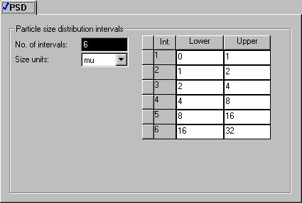
The Setup | Substreams | PSD | PSD sheet appears. Use this sheet to modify the default particle size distribution.
5In the No. of intervals field, enter 6.
6Enter the following six intervals to describe the particle size distribution. Each Upper value is automatically copied to the next Lower value.
Interval |
Lower [mu] |
Upper [mu] |
1 |
0 |
1 |
2 |
1 |
2 |
3 |
2 |
4 |
4 |
4 |
8 |
5 |
8 |
16 |
6 |
16 |
32 |
4-6 • Modeling Gas-Solid Separators |
Getting Started - Solids |
Updating Particle
Size Distributions
Previously Entered
Changing the intervals of the particle size distribution (PSD) modifies the particle size distributions you entered in the previous simulations.
1In the Data Browser menu tree, select the Streams | WETCOAL | Input form.
2Click the PSD tab.
The Streams | WET-COAL | Input | PSD sheet appears. The original PSD for this stream used size intervals 7 through
10.Since you just deleted intervals 7 through 10, the PSD is now empty and you must provide a new PSD. Because the coal is combusted before it reaches any of the solids-handling unit operation models, an accurate PSD for coal is not necessary.
3Enter a value of 1.0 for the Weight Fraction between 16 and
32microns.
You must also modify the particle size distribution you specified in the RYield block DECOMP.
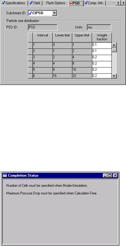
4In the Data Browser menu tree, select the Blocks | DECOMP | Setup form.
5Select the PSD tab.
The Blocks | DECOMP | Setup | PSD sheet appears.
6In the Substream field, click  and select CIPSD.
7Enter the following values of Weight Fraction for the CIPSD substream. (These particle size distributions are chosen for illustrative purposes only and are not meant to be typical of an industrial application.)
Interval Weight Fraction
10.1
20.1
30.2
40.2
50.2
60.2
Getting Started - Solids |
Modeling Gas-Solid Separators • 4-7 |
8In the Substream field, click  and select NCPSD.
9Enter the same weight fractions for the particle size distribution for the NCPSD substream that you entered for the CIPSD substream above.
10Click  to continue.
Specifying the Solids-Handling
Blocks
The BAG-FILT | Input | Specifications sheet appears.
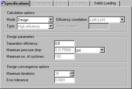
1 Click  to find out what must be specified on this sheet.
4-8 • Modeling Gas-Solid Separators |
Getting Started - Solids |

2Click  to close the Completion Status window.
Use the design mode of the fabric filter model (FabFl), not the simulation mode. Simulation mode determines the capacity of an existing piece of equipment. Design mode determines the size of a new piece of equipment with a given capacity.
3In the Mode field, click  and select Design.
4Click  to determine what input is required for the FabFl model in design mode.
In design mode, FabFl requires a specification for the maximum pressure drop.
5Click  to close the Completion Status window.
6In the Maximum pressure drop field, enter a value of 0.5 psi.
7Click  to continue.
The COOLER | Input | Specifications sheet appears. This block cools the gas after combustion, allowing the solid ash to be removed. The Heater block requires two thermodynamic specifications.
8In the Temperature field, enter 400 F.
9In the Pressure field, enter 14.7 psi.
10Click  to continue.
The CYCLONE | Input | Specifications sheet appears.
Getting Started - Solids |
Modeling Gas-Solid Separators • 4-9 |
To Learn About the
Cyclone Model Using
Help
1From the main toolbar, click  .
.
2Click anywhere in the CYCLONE | Input | Specifications sheet. If a small popup help window appears, click the link for Sheet Help.
The help for the Cyclone Input Specifications sheet appears.
3In the See Also list at the end of the topic, click the Specifying Cyclone hypertext link.
4Use the links, scrollbars, and arrow keys to move through the topics.
5After reviewing the help, click  to close the help window.
6In the Mode field, click  and select Design.
7In the Separation efficiency field, enter a separation efficiency of 0.8.
No further specifications are required for CYCLONE.
8Click  to continue.
The ESP | Input | Specifications sheet appears.
9In the Mode field, click  and select Design.
10In the Separation efficiency field, enter 0.995.
4-10 • Modeling Gas-Solid Separators |
Getting Started - Solids |

11Click the Dielectric Constant tab.
12Specify a dielectric constant of 5.0 for both CIPSD and NCPSD substreams. (The value of the dielectric constant is for illustrative purposes only.)
13 Click  to continue.
Getting Started - Solids |
Modeling Gas-Solid Separators • 4-11 |