

156 ELECTROSURGICAL UNIT (ESU)
cone function, in clinical circumstances the mfERG should always be taken in conjunction with conventional full-field ERG.
CONCLUSIONS AND FUTURE DIRECTIONS
Diagnosis and management of the patient with visual pathway disease is greatly assisted by the objective functional information provided by electrophysiological examination. Separation of the function of different retinal cell types and layers enables characterization both of acquired and inherited retinal disorders, of great importance when counseling families affected by or at risk of a genetically determined disease. The PERG is complementary to the ERG by providing a measure of central retinal function; the mfERG may play a similar role.
BIBLIOGRAPHY
Cited References
1.Corbett MC, Shilling JS, Holder GE. The assessment of clinical investigations: the Greenwich grading system and its application to electrodiagnostic testing in ophthalmology. Eye 1995;9 (Suppl.): 59–64.
2.Holder GE. The pattern electroretinogram and an integrated approach to visual pathway diagnosis. Prog Retin Eye Res 2001;20:531–561.
3.Marmor MF. Standardization notice: EOG standard reapproved. Doc Ophthalmol 1998;95:91–92.
4.Marmor MF, Holder GE, Seeliger MW, Yamamoto S. Standard for clinical electroretinography (2004 update). Doc Ophthalmol 2004;108:107–114.
5.Bach M et al. Standard for Pattern Electroretinography. Doc Ophthalmol 2000;101:11–18.
6.Odom JV et al. Visual Evoked Potentials Standard (2004). Doc Ophthalmol 2004;108:115–123.
7.Heckenlively JR, Arden GB, editors. Principles and Practice of Clinical Electrophysiology of Vision. St. Louis: Mosby Year Book; 1991.
8.Fishman GA, Birch DG, Holder GE, Brigell MG. Electrophysiologic Testing in Disorders of the Retina, Optic Nerve, and Visual Pathway. 2nd ed. Ophthalmology Monograph 2. San Francisco: The Foundation of the American Academy of Ophthalmology; 2001.
9.Marmor MF, et al. Guidelines for basic multifocal electroretinography (mfERG). Doc Ophthalmol 2003;106:105–115.
10.Hood DC, Birch DG. Rod phototransduction in retinitis pigmentosa: Estimation of parameters from the rod a-wave. Invest Ophthalmol Vis Sci 1994;35:2948–2961.
11.Shiells RA, Falk G. Contribution of rod, on-bipolar, and horizontal cell light responses to the ERG of dogfish retina. Vis Neurosci 1999;16:503–511.
12.Bush RA, Sieving PA. Inner retinal contributions to the primate photopic fast flicker electroretinogram. J Opt Soc Am A 1996;13:557–565.
13.Bush RA, Sieving PA. A proximal retinal component in the primate photopic ERG a-wave. Invest Ophthalmol Vision Sci 1994;35:635–645.
14.Sieving PA. Photopic ONand OFF-pathway abnormalities in retinal dystrophies. Trans Am Ophthalmol Soc 1993; 91:701–773.
15.Koh AHC, Hogg CR, Holder GE. The Incidence of Negative ERG in Clinical Practice. Doc Ophthalmol 2001;102: 19–30.
16.Arden GB et al. S-cone ERGs elicited by a simple technique in normals and in tritanopes. Vision Res 1999;39:641–650.
17.Arden GB et al. A gold foil electrode: extending the horizons for clinical electroretinography. Invest Ophthalmol Vision Sci 1979;18:421–426.
18.Dawson WW, Trick GL, Litzkow CA. Improved electrode for electroretinography. Invest Ophthalmol Vision Sci 1979;18: 988–991.
19.Hawlina M, Konec B. New noncorneal HK-loop electrode for clinical electroretinography. Doc Ophthalmol 1992;81:253– 259.
20.Berninger TA. The pattern electroretinogram and its contamination. Clin Vision Sci 1986;1:185–190.
21.Holder GE. Significance of abnormal pattern electroretinography in anterior visual pathway dysfunction. Br J Ophthalmol 1987;71:166–171.
22.Viswanathan S, Frishman L J, Robson JG. The uniform field and pattern ERG in macaques with experimental glaucoma: removal of spiking activity. Invest Ophthalmol Vis Sci 2000;41:2797–2810.
23.Holder GE, Robson AG, Pavesio CP, Graham EM. Electrophysiological characterisation and monitoring in the management of birdshot chorioretinopathy. Br J Ophthalmol 2005; in press.
24.Lois N, Holder GE, Bunce C, Fitzke FW, Bird AC. Stargardt macular dystrophy—Fundus flavimaculatus: Phenotypic subtypes. Arch Ophthalmol 2001;119:359–369.
See also BLIND AND VISUALLY IMPAIRED, ASSISTIVE TECHNOLOGY FOR;
CONTACT LENSES; VISUAL PROSTHESES.
ELECTROSHOCK THERAPY. See ELECTROCONVULSIVE
THERAPY.
ELECTROSTIMULATION OF SPINAL CORD. See
SPINAL CORD STIMULATION.
ELECTROSURGICAL UNIT (ESU)
JOHN PEARCE
The University of Texas
Austin, Texas
INTRODUCTION
Electrosurgery means the application of radio frequency (RF) current at frequencies between 300 kHz and 5 MHz to achieve a desired surgical result; typically the fusion of tissues or surgical cutting in which the tissue structure is disrupted. In either case, the effect is achieved by heat dissipated in the tissues from the RF current by resistive, or joule, heating. This method has the ability to cut and coagulate tissues simultaneously; and, as a consequence, has made substantial contributions to several branches of clinical medicine since its introduction in the late 1920s.
The tissue effects applied in electrosurgery are typically described as (a) white coagulation, named for its appearance, in which the tissue proteins are degraded at lower temperatures, typically 50–90 8C; (b) black coagulation or carbonization in which tissues are completely dried out (desiccated) and reduced to charred carbonaceous
remnants at higher temperatures; and (c) cutting in which tissue structures are separated by the rapid boiling of small volumes of tissue water. These three results usually occur in some combination depending on the applied current and voltage at the so-called active or surgical electrode.
Electrosurgery accomplishes many surgical jobs better than any other device or technique while drastically reducing the morbidity and mortality associated with surgery. It does this by reducing the time under anesthesia and complications due to operative and postoperative hemorrhage. Many of the delicate techniques in neurosurgery would be impossible without electrosurgery—and it is likely that open heart surgery and much of urologic surgery would likewise not be done.
Historical Background
The application of heat for the treatment of wounds dates back to antiquity. According to Major (1), Neolithic skulls unearthed in France show clear evidence of thermal cauterization. The Edwin Smith papyrus ( 3000 BC) (2) describes the use of thermal cautery for ulcers and tumors of the breast. Licht (3) reports that according to Jee (4) the ancient Hindu god Susruta, the highest authority in surgery, said that ‘‘caustic is better than the knife, and the cautery is better than either.’’ Cautery in ancient Hindu medicine included heated metallic bars, boiling liquids, and burning substances.
In cauterization the essential physical mechanism behind the treatment is conduction heat transfer from a hot object placed on the surface to raise the temperature high enough to denature the tissue proteins. Cutting and coagulation by means of electrosurgery is also accomplished by heating tissue to high temperatures, but the essential difference is that the primary mechanism is electrical power dissipation directly in the affected tissues themselves, rather than heat transfer from an external hot object on the tissue surface. It is rather like the difference between heating food in a conventional oven and a microwave oven, in a loose sense. Electrosurgery is sometimes erroneously referred to as electrocautery. Since the physical mechanisms are different it is important to keep these two techniques separate by precise terminology. Electrosurgery is also referred to as surgical diathermy, particularly in Europe. While this term is generally understood, it is a bit of a misnomer since diathermy literally means through-heating, such as might be applied in physical medicine for the relief of pain or in hyperthermia therapy for tumor treatment. Electrosurgical devices in operating rooms are designed and built for surgical use only, and the terminology in this section is standardized on that basis.
Early Experiments with High Frequency Current. The origin of the application of rf current to achieve surgical results is difficult to establish owing to the rapid pace of development in the electrical arts during the late nineenth and early twentieth centuries. Lee De Forrest, the inventor of the vacuum tube (the audion, 1907 and 1908), filed a patent for a spark gap rf generator to be used for electrosurgery in February of 1907 (it was granted in December of 1907) (5). Also, during the same year, Doyen noted that the
ELECTROSURGICAL UNIT (ESU) |
157 |
effect of a surgical arc on the tissue was not a function of the length of the arc, and that the temperatures of carbonized tissue were as high as 500–600 8C (6). He also found that final temperatures in the range of 65–70 8C resulted in white coagulation while there was no damage to tissues for temperatures < 60 8C (7).
By far, the most effective promoters of electrosurgery were Cushing and Bovie. W. T. Bovie was a physicist attached to the Harvard Cancer Commission. He had developed two electrosurgical units, one for coagulating and one for cutting. Harvey Cushing, the father of neurosurgery, had been concerned for some time with the problem of uncontrolled hemorrhage and diabetes insipidus, the often fatal complications of hypophysectomy, among other concerns (8). In 1926, working with Bovie, he applied high frequency current in cerebral surgery with excellent results. They published their work in 1928, emphasizing the three distinct effects of electrosurgery: desiccation, cutting and coagulation (9).
Early Electrosurgical Generators. Cameron-Miller offered the Cauterodyne in 1926, similar to the later model of 1930 that featured both vacuum tube cutting and spark gap coagulation. It came in a burled walnut bakelite case for $200. It is not known if the original 1926 device included tube cutting. The device designed and manufactured by W. T. Bovie was of higher fundamental frequency than the other early devices. The Bovie device used a 2.3 MHz vacuum tube oscillator for pure cutting (i.e., Cut 1) and a 500 kHz fundamental frequency spark gap oscillator for fulguration and desiccation (Cut 2–4 and Coag). The overall size, circuit and configuration of the Bovie device remained essentially constant through the 1970s. Bovie’s name is so closely associated with electrosurgery that it is frequently referred to as the Bovie knife in spite of the extensive work which preceded his device and the numerous devices of different manufacture available then and now. In essence, the available electrosurgical generators between 1930 and the 1960s were of the similar design to that used by Bovie, and consisted of a spark gap generator for coagulating and a vacuum tube generator for cutting.
The introduction of solid-state electrosurgical generators in the early 1970s by Valleylab and EMS heralded the modern era of isolated outputs, complex waveforms, more extensive safety features and hand-activated controls. Interestingly, hand-activated controls are actually a recent rediscovery and improvement on those used by Kelly and Ward (10) and those available on the Cauterodyne device. In some ways, higher technology devices of all designs are made inevitable by the recent proliferation of delicate measurement instrumentation that is also attached to a patient in a typical surgical procedure.
Clinical Applications
The topics chosen in this introductory survey are by no means comprehensive. Those readers interested in specific surgical techniques should consult the texts by Kelly and Ward (10) and Mitchell et al. (11) for general, gynecologic, urologic and neurosurgical procedures; Otto (12) for minor
158 ELECTROSURGICAL UNIT (ESU)
electrosurgical procedures; Harris (13), Malone (14), and Oringer (15,16) for dental electrosurgery; and Epstein (17) and Burdick (18), for dermatologic procedures.
When high frequency currents are used for cutting and coagulating, the tissue at the surgical site experiences controlled damage due either to disruptive mechanical forces or distributed thermal damage. Cutting is accomplished by disrupting or ablating the tissue in immediate apposition to the scalpel electrode. Continuous sine waveforms (e.g., those obtained from vacuum tube or transistor oscillators) have proven most effective for cutting. Coagulating is accomplished by denaturation of tissue proteins due to thermal damage. Interrupted waveforms, such as exponentially damped sinusoids (obtained from spark gap or other relaxation-type oscillators) are effective for coagulation techniques requiring fulguration, or intense sparking (fulgur is Latin for lightning). However, when no sparks are generated, coagulation is created by tissue heating alone, and the specific waveform is immaterial: only its effective heating power, or root-mean-square (rms) voltage or current determine the extent of the effect. Suffice it to say that the difference between cutting and coagulation is due to combined differences in heat-transfer mechanisms and spatial distribution of mechanical forces. In general, the tissue damage from cutting current is confined to a very small region under the scalpel electrode and is quite shallow in depth. Cells adjacent to the scalpel are vaporized and cells only a few cellular layers deep are essentially undamaged. Though dependent on surgical technique, generally only the arterioles and smaller vessels are sealed when a cut is made using pure sine wave currents. Coagulation currents are used to close larger vessels opened by the incision, to fuse tissue volumes by denaturing the proteins (chiefly the collagen) and to destroy regions of tissue. The tissue damage when coagulating is deeper than when cutting. In the majority of applications for coagulating current, the damage in the tissue is cumulative thermal damage rather than tissue disruption or ablation.
Cutting is a monopolar procedure, although some experiments have been performed with bipolar cutting. That is, the scalpel electrode represents essentially a point current source and the surgical current is collected at a remote site by a large area dispersive, or return electrode. Coagulation may be accomplished using either monopolar or bipolar electrodes. In bipolar applications, both the current source and current sink electrodes are located at the surgical site. A typical bipolar electrode might consist of forceps with the opposing tongs connected the two active terminals of the generator. In both cutting and coagulating processes, whether monopolar or bipolar electrodes are used, a layer of charred tissue often condenses on the cool electrode that must periodically be removed (19).
The histologic effects of cutting current are varied and apparently depend on technique. Knecht et al. (20) found that the healing process in an electrosurgical incision was a bit slower than for incisions made by a cold scalpel. In their study, the wound strength of an electrosurgical cut was less than that of a cold scalpel cut until 21 days after surgery. After 21 days, no difference in wound strength was measurable. Ward found that an electrosurgical cut
generally formed slightly more scar tissue on healing than a cold scalpel cut if the closure of the two wounds was identical (21). The cellular layers within 0.1 mm of the scalpel electrode showed electrodesiccation effects when sine wave cutting was used (21). In a later series of studies on tissues of the oral cavity, Oringer observed that when the cutting current was carefully controlled, the damage was confined to the cut cellular layer, and the layer of cells adjacent to the cut was undamaged (14,15). The cell destruction was apparently self-limiting to the extent that no damage to the cytoplasm or cell nucleus of the cut layer was visible in light or electron micrographs (14). Oringer (16) describes the margin of an excised squamous cell carcinoma that had been removed with electrosurgery. Under the electron microscope at a magnification of 47,400 the margin was seen to contain several clear examples of cells sheared in half with no damage to the remainder. Oringer, and others, observed faster healing with less scar tissue in the electrosurgical incision. The variety of results obtained is likely due to differences in waveform, surgical technique, tissue characteristics and scalpel electrodes used in the studies.
When combined sine wave and interrupted (coagulating) waveforms are used, or when spark gap sources are used for cutting, a coagulum layer extends deeper into the tissues under the desiccated layer (21). Coagulation techniques include (1) fulguration (also called spray coagulation or black coagulation) in which the tissue is carbonized by arc strikes, (2) desiccation, in which the cells are dehydrated resulting in considerable shrinking, and (3) white coagulation, in which the tissue is more slowly cooked to a coagulum. In fulguration techniques, the active electrode is held a few millimeters from the surface of the tissue and arcs randomly strike from the electrode to the tissue. The cell structure is destroyed at a very high temperature resulting in charring of the tissue. In desiccation, the water is evaporated from the cell relatively slowly leaving a white dry flake of powder, the cells appear shrunken and drawn out with elongated nuclei. The overall cellular anatomical characteristics are preserved (21). Desiccation techniques normally take longer to accomplish than fulguration for the same volume of tissue. In white coagulation, the electrode is in intimate contact with the tissue. No arcs strike so the electrode voltage is low by comparison. The total electrode current may be high, but the tissue current density (current per unit area) at all points on the electrode is moderate and the duration of the activation is therefore relatively long. The cellular effects are varied, ranging from a tough coagulum when connective tissue predominates to granular debris easily removed by a curet when the majority of the tissue is epithelial (21). Often the goal of coagulation is to shrink and fuse or thermally damage tissue collagen.
Minor Surgery. Minor surgery may be described as surgery applied to tissues on exterior surfaces of the body under local anesthetic, which includes dermatology. Other external surfaces, which include oral, vaginal and cervical tissues, are also routinely treated as minor surgery cases on an outpatient basis or in the office. Typical minor surgery procedures include the removal of warts, moles
“ Cut ” “ Coag ” Handswitch
Metal Blade
Blade Cross-Section
(a)Scalpel blade electrode
(b)Needle electrode
(c)Ball electrode
(d) Cutting loop
Bipolar
(e) Bipolar nasal turbinate electrode
ELECTROSURGICAL UNIT (ESU) |
159 |
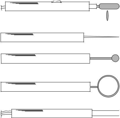
Figure 1. Electrodes typically used for general electrosurgery.
and vascular nevi, the surgical reduction of sebaceous cysts, epiliation, cervical conization, relief of chronic nasal obstruction, and the removal of polyps and tumors. The techniques used in minor surgery are very similar to those of general surgery, although the cutting electrodes come in a wider variety of shapes and sizes.
Figure 1 illustrates some of the electrodes used (19). The standard scalpel blade electrode used for incision is elliptical in cross-section with a cutting edge which is of small radius (not sharp) in order to yield the very high current densities required for tissue ablation. The scalpel electrode is sometimes angled for special techniques. Scalpel electrodes are usually used for incisions, but may also be used for coagulation. The flat side of the blade can be applied to a tissue mass to obtain coagulation. The tip of the electrode may be suspended above the tissue for fulguration. Other electrode shapes accumulate less carbonized tissue residue than the scalpel, and are often preferred for coagulation. The needle, standard coagulation and ball electrodes are used either for desiccation or fulguration. The ball electrode may be used with coagulating current to treat persistent nose bleed that does not respond to other methods.
Bipolar forceps and the turbinate electrode are used in bipolar procedures. The forceps electrode has one electrical connection on each side of the forceps, and is used, for example, to grasp a seeping vessel; current between the forceps electrodes then seals off the vessel end by fusing the vessel walls together. The turbinate electrodes are used to
obtain submucous coagulation (desiccation) in the nasal turbinates for relief of chronic vasomotor rhinitis: swelling of the soft tissue in the nasal cavity caused by, for example, allergies or irritants.
Neurosurgery and General Surgery. Blood is toxic to neural tissue. Consequently, blood loss during neurosurgery is to be avoided at all costs. At its inception, electrosurgery presented the first technique that accomplished cutting with negligible blood loss. This was this feature of electrosurgery that so strongly attracted Cushing. Many of the now commonplace neurosurgical procedures would be impossible without some method for obtaining hemostasis while cutting.
White coagulation is generally used in neurosurgery since it does not cause charring. White coagulation takes a relatively long time to obtain compared to fulguration or cutting. Holding the scalpel electrode to a location for long activation times allows deep penetration of the high temperature zone. This effect is used to advantage in rf lesion generation for selective disabling of neural tissue. Bipolar applicators restrict the current to a smaller region and are used extensively for microneurosurgical techniques, since they are more precise and safer. Many of the techniques are properly classed as microsurgery. Often the tissue being cut or coagulated is stabilized with a suction probe while current is applied. The suction probe is usually nonconductive glass or plastic; however, on occasion a metal

160 ELECTROSURGICAL UNIT (ESU)
suction probe is used with monopolar coagulation to localize the current to the immediate area (11). Incisions of the cerebral cortex are usually made with monopolar needle electrodes. Surface tumors are removed by applying a suction probe to the tumor and excising it at the base with a cutting loop.
Dental Electrosurgery. The tissues of the oral cavity are particularly highly vascularized. Also, the mouth and alimentary canal contain high concentrations of bacteria. Since the ability to ingest food is critical to survival these tissues are among the fastest healing of the body. Electrosurgery plays an important role in oral surgery in that it drastically reduces bleeding that would obscure the operative field and the undesirable postoperative effects of pain, edema and swelling in the submaxillary triangle (15). It can be quite difficult to accurately resect redundant tissue masses by cold scalpel techniques in the oral cavity. Electrosurgery allows accurate resection with minimal elapsed time and complications, an important feature when fitting prosthodontic devices. Electrosurgery reduces the hazard of transient bacteremia and secondary infection (14), and the danger of surgical or mechanical metastasis of malignant tumor emboli during biopsy (15). In short, all of the advantages obtained in other types of surgery are experienced in dental surgery as well as some additional beneficial aspects.
The active electrodes used in dental electrosurgery are for the most part similar to those shown in Fig. 2 (19). Several shapes specific to dental procedures are: the open hook electrodes in Fig. 2a are used along with other needle
(a)
(b) |
Figure 2. Electrodes typically used for dental electrosurgery.
(a) Open hooks and needles, straight and angulated to reach difficult locations. (b) Straight and angulated cutting loops.
electrodes to create subgingival troughs, those in Fig. 2b are used with ball electrodes, and loop electrodes for seating orthodontic appliances and denture prostheses and exposing roots. Other interesting applications include the removal of premalignant neoplastic lesions from the surface of the mucosa using a planing loop and the removal of tissue masses from the tongue. Carefully applied electrosurgery can be used to advantage on teeth as well as the soft tissues of the oral cavity.
Urologic Surgery. Electrosurgery is used extensively in urologic procedures. Urologic procedures, specifically transurethral resections of the prostate, utilize by far the highest currents at high voltage for the longest durations and largest number of activations per procedure of any electrosurgical technique. Other urologic applications of electrosurgery include: the resection of bladder tumors, polyp removal by means of a snare electrode or desiccating needle, kidney resection to remove a stone-bearing pocket, and enlarging the urethral orifice in order to pass stones. These other procedures utilize power levels similar to those of general surgery.
A transurethral resection is intended to increase the caliber of a urethra that has been partially closed by an enlarged prostate gland. This procedure is one of the earliest applications of electrosurgery in urology, having been described in considerable detail by Kelly and Ward in 1932 (21). During transurethral resection, the urethra is irrigated with a nonconductive sterile solution, either dextrose or glycerine, while a cutting loop is advanced to remove the encroaching tissue. Surgical cutting accomplished in a liquid medium requires higher currents since the liquid carries heat away and disperses the current (even though it is nonconductive) more than a gaseous environment would. A typical resectoscope used in this procedure is shown diagrammatically in Fig. 3. A long outer metal sheath, which is plastic coated, contains a cutting loop that can be extended from the sheath, a fiber optic cable bundle for viewing the cutting action, an illumination source (either a bulb at the end or an illumination fiber optic bundle), and spaces for influx and efflux of irrigating fluid. The cutting loop (of thin diameter to yield the high current densities required) is moved in and out of the sheath by the surgeon as required to accomplish the resection.
Gynecologic Surgery. One of the common gynecologic applications of electrosurgery is cervical conization. Other common gynecologic applications of electrosurgery include the removal of tumors, cysts, and polyps. The use of electrosurgery in laparoscopic tubal ligations will be treated in some detail since it is also a very common procedure. The laparoscopic tubal ligation is a minimally invasive sterilization procedure typically accomplished by advancing an electrode through a small incision in order to coagulate the Fallopian tube. The position of the uterus is fixed by a cannula inserted through the cervix under the surgeon’s control. The abdominal cavity is insufflated with CO2 gas in order to separate the tissue structures. The coagulating electrode is then advanced through a small incision in the abdominal wall to the Fallopian tube by the surgeon,

ELECTROSURGICAL UNIT (ESU) |
161 |
observing through an endoscope (laparoscope), which has been inserted through a separate small incision. The isolated Fallopian tube is then coagulated at high current but relatively low voltage.
Both monopolar and bipolar electrosurgical electrodes have been used for this procedure; however, monopolar tubal ligation methods are to be avoided as there have been many instances of bowel wall perforations and other complications following monopolar tubal ligation procedures owing to surgical current flow in the bowel wall. Bipolar techniques confine the current to a small region of tissue and the risk of bowel perforation is minimal in comparison. A bowel wall perforation can still result due to heat transfer from the coagulated tissue, so the coagulating forceps and Fallopian tube must be held away from the bowel wall and allowed to cool before being released. Note that a surrounding CO2 gas environment will increase the time required for tissue cooling.
FUNDAMENTAL ENGINEERING PRINCIPLES
OF ELECTROSURGERY
RF Generators for Electrosurgery
In general, the RF frequencies used for electrosurgery fall between 350 kHz and 4 MHz, depending on manufacturer and intended use. The available output power ranges from30–300 W. Peak open circuit output voltages vary from < 200 V to 10 kV. Higher open circuit voltages are used to strike longer arcs for fulguration, while the lower voltages are used for bipolar coagulation. Most devices are capable of generating several different waveforms, said to be appropriate for differing surgical procedures.
Vacuum Tube and Spark Gap Oscillators. The original rf generators used in electrosurgery, diathermy, radiotelegraphy, and radar circuits were spark gap oscillators (Fig. 4). The exponentially damped sine wavefrom (Fig. 4b) results from a breakdown of the spark gap (SG in Fig. 4a) that initializes the oscillations. The waveform is often called a Oudin waveform, though it is typical of all spark gap units, Oudin output circuit or not. The RFC is a RF choke to prevent the rf signal from coupling to the power line. Later generator designs utilized vacuum tube oscillator circuits that were typically Tuned-Plate, TunedGrid Oscillators (22), as shown in Fig. 5a (Birtcher Electrosectilis), or Hartley oscillators, Fig. 5b (Bovie AG). The output of vacuum tube electrosurgical units is available as either partially rectified [meaning that the RF oscillator is active only on one of the half-cycles of the mains power (i.e., one vacuum tube)] or fully rectified [meaning that the RF
Figure 3. Resectoscope typical for transurethral resections of the prostate (TURP).
oscillator is active on both half-cycles of the mains power (Fig. 5c)]. In both circuits of Fig. 5 each vacuum tube, V1 and V2, oscillates on opposite half cycles of the mains power, period T. Electrosurgery generator designs varied little from the standard units built by Bovie and CameronMiller in the 1920s until 1970 when solid-state generators became available. Solid-state generators made possible much more sophisticated waveforms and safety devices in a smaller overall package. Though not specific to solidstate technology, isolated outputs became common when solid-state electrosurgery units were introduced. Until1995 all electrosurgery generators acted essentially as voltage sources with a typical output resistance in the
Figure 4. Spark gap oscillator rf generator. (a) Spark gap oscillator circuit. SG ¼ spark gap, which acts as a switch, RFC ¼ radio frequency choke, L and C determine the fundamental rf frequency, f0 and R the damping (R ¼ the patient). (b) Oudin waveform with amplitude determineed by the supply voltage peak, Vs. (c) Frequency spectrum of the output Oudin waveform has energy centered at 0, the fundamental RF oscillation frequency with energy concentrated at harmonics of the repeat frequency to both high and low frequencies.

162 |
ELECTROSURGICAL UNIT (ESU) |
|
|
|
|
|
V S |
RFC |
|
|
|
|
V1 |
L/2 |
|
|
|
|
L |
|
Cout |
+ |
|
|
|
|
|
||
|
1 |
|
|
v(t) |
|
|
R |
|
|
|
|
|
C |
Cout |
|
|
|
|
Vh |
|
− |
|
|
|
|
|
|
|
|
|
V2 |
L/2 |
|
|
|
|
|
|
|
|
|
|
|
(a) |
|
|
|
|
RFC |
Cg |
C |
|
|
|
|
L |
|
+ |
|
|
V1 |
|
Cout |
||
|
|
v(t) |
|||
|
Rg |
|
|||
|
|
|
|
− |
|
Mains |
|
|
|
|
|
|
Rg |
|
|
|
|
Power |
|
|
|
|
|
|
V2 |
|
L |
Cout |
|
|
|
|
|
||
|
RFC |
Cg |
C |
|
|
|
|
|
|
||
|
|
(b) |
|
|
|
|
T |
|
|
|
|
|
|
|
t |
|
|
|
|
(c) |
|
|
|
Figure 5. Vacuum tube electrosurgical circuits. (a) Tuned plate, tuned grid oscillator, as used in the Birtcher Electrosectilis.
(b) Modified Hartley oscillator, as used in the Bovie AG. (c) Fully rectified output waveform.
neighborhood of 300–500 V. Recent generator designs incorporate embedded microprocessors and have constant power delivery modes. Interestingly, both Bovie and Cameron-Miller electrosurgical devices are available in the present day, though the designs are considerably different.
Solid-State Generators. Solid-state electrosurgical generators generally operate on a different design principle than the vacuum tube devices. Rather than combine the oscillator and power amplifier into one stage, solid-state generators utilize wave synthesis networks that drive a power amplifier output stage. This approach has the advantage that quite complex waveforms may be employed
for cutting and coagulating; although to date the waveforms used vary little, if at all, from those of vacuum tube and spark gap oscillators. Many solid-state generators (chiefly those with bipolar transistors in the output amplifier) do not have as high open circuit output voltages as vacuum tube and spark gap devices. It sometimes appears to the user of those devices that there is less power available for cutting and coagulating since the lower open circuit voltages will not strike arcs as far away from the tissue. This turns out to be a limitation of concern in the high voltage procedures, namely in TURPs, but not in high current procedures, such as laparoscopic tubal ligations. In general, solid-state generators that use bipolar transistors in the high voltage output amplifier stage are vulnerable to transistor failure. The more recently introduced solid-state generators (after 1985) employ high voltage VMOS or HEXFET field effect transistors (23) in the output stage to give higher open circuit voltages and/or to reduce the stress on the bipolar output transistors.
A general block diagram of a typical solid-state electrosurgical generator is shown in Fig. 6 (24). The fundamental frequency, most often 500 kHz, is generated by a master oscillator circuit, typically an astable multivibrator. The primary oscillator acts as the clock or timing reference for the rest of the generator. The unmodified master oscillator signal is amplified and used for cutting. An interrupted waveform is formed by gating the continuous oscillator output through an external timing circuit, as shown in the figure. The repeat frequency of the timer is typically on the order of 20 kHz (24), much higher than that of spark gap oscillators. The duty cycle of a waveform is the ratio of duration of the output burst to the time between initiation of bursts. Duty cycles for solid state coagulating waveforms vary, but a duty cycle of 10–20% would be considered typical. This is in sharp contrast to the spark gap devices that have duty cycles often < 1%. The higher duty cycle of solid-state units compensates in part for their lower peak output voltages so the actual maximum available power is similar in both families of devices.
Constant power output is obtained by measuring the output voltage and current and adjusting the drive signal to compensate for changes in the equivalent load impedance (25), as in Fig. 7a. The sampling rate for this adjustment is on the order of hundreds of hertz ( 200 Hz for the device depicted). In Fig. 7b, the performance of the example system is compared to a standard voltage source generator
Figure 6. Block diagram for typical solid state ESU. Footswitch (and hand switch) controls simplified by omitting the interlock circuitry that prevents simultaneous activation. Master oscillator sets fundamental RF frequency, f0. Interrupted waveform repeat frequency, frep. Provisions for blending cut and coag modes often provided. Power amplifier either bipolar junction transistors or HEXFET or VMOS transistors.
Master |
|
Panel |
|
|
oscillator |
|
control |
|
|
f0 |
|
Cut |
|
Active |
|
Level |
|
||
|
|
|
||
|
|
|
|
|
|
control |
Power |
Output |
Patient |
|
|
impedance |
||
|
|
amplifier |
leads |
|
|
|
matching |
||
|
Level |
|
|
|
Modulator |
|
|
|
|
control |
Coag |
|
|
|
|
|
Return |
||
|
|
Footswitch |
|
|
|
|
|
|
|
Relaxation |
|
|
|
|
oscillator |
Panel |
|
|
|
frep |
|
|
||
control |
|
|
||
|
|
|
||

|
|
Scale output measurement |
Current sense |
|
|
|
|
|
|
calculate output power |
|
Amplitude |
Power |
|
|
control |
amplifier |
|
|
|
|
Output |
Voltage |
|
|
sense |
|
RF |
|
transformer |
|
|
|
|
|
source |
|
|
|
|
|
(a) |
|
|
300 |
|
|
(W) |
200 |
|
|
power |
|
|
|
|
|
|
|
Output |
100 |
|
|
|
|
|
|
|
0 |
|
|
0 500 1000 1500 Load resistance (Ω)
(b)
ELECTROSURGICAL UNIT (ESU) |
163 |
Active
Patient
leads
Return
Figure 7. Constant power generator system. (a) Descrip2000 tive block diagram. (b) Typical performance (squares) compared to standard voltage source with fixed source voltage and equivalent output impedance (solid line), Nominal
250 W into 300 V (24).
with fixed output impedance 300 V and maximum output power of 250 W at 300 V load impedance. The differences at high load impedances typical of electrosurgical cutting (up to 2 kV) are easily seen in the figure.
Safety Appliances. Since the electrosurgical unit (ESU) represents a high power source in the operating room, the potential for adverse tissue effects and accidental results must be managed. One of the more common types of accident has historically been one or more skin burns at the dispersive, or return, electrode site (during monopolar procedures). Often these have resulted from the return electrode losing its attachment to the skin. Earlier ESU designs incorporated a so-called circuit sentry, or its equivalent, which ensured that the return electrode cable made contact with the return electrode by means of monitoring current continuity through the cable and electrode connection at some low frequency. This ensured that the electrode was connected to the ESU, but did not ensure that it was connected to the patient.
Modern ESU devices monitor the patient return electrode to ensure its continued connection to the skin. In these devices, the patient return electrode is divided approximately into halves and a small current (typically on the order of 5 mA or less) at high frequency but below the surgical frequency (typically in the neighborhood of 100 kHz) is applied between the electrode halves, the connection being through the skin, only, as in Fig. 8 (25). The impedance between them is monitored, and if it exceeds maximum or minimum limits, or a set fraction of
the baseline value (typically 40% or so over the baseline) an alarm sounds and the generator is deactivated. The patient return monitor system resets the baseline impedance if it falls below the initial value.
The high frequency of operation of electrosurgery units also contributes to the hazards associated with its use. At very high frequencies, current may flow in two different ways. First, in good conductors, such as skin and other wet tissues, the current flows by conduction and Ohm’s law applies. Second, in insulating dielectric substances, such as air, surgical rubber or plastic, the current flows as so-called displacement current. The value of the displacement current density is linearly related to the frequency, so for the same materials, voltages and geometric arrangement of conductors, higher frequencies conduct more displacement current in dielectric substances than do lower frequencies. A consequence of this relationship is that at electrosurgical frequencies and voltages the capacitance between the wire conductor in a scalpel electrode and tissue over which the wire passes may have low impedance if the insulation is thin. Scalpel electrode wires are covered with thick insulation of high dielectric constant in order to prevent tissue damage at high scalpel electrode voltages. If the wire is inadequately designed or the insulation is damaged, the displacement current in the wire insulation may be dense enough to cause damage to the underlying tissue.
Electrosurgical unit outputs may be isolated, referred to ground, or grounded terminals (Fig. 9). Grounded patient return leads (Fig. 9a) have a hard wired connection to the ESU chassis ground wire. Referred to ground means that

164 ELECTROSURGICAL UNIT (ESU)
Figure 8. Patient return monitor circuit ensures that the return electrode remains attached to the patient. Split return electrode conforms to patient contours; both halves of return electrode carry surgical rf current. Insulator prevents lower frequency interrogation current from finding a shorter pathway. Current pathway is through the patient’s skin, ensuring contact.
there is a fixed impedance, typically a capacitor, between the patient return lead and ground (Fig. 9b). The capacitance is chosen to represent a low impedance at the ESU rf frequency and a high impedance at power mains frequency and frequencies associated with stimulation of electrically excitable tissues. Isolated outputs (Fig. 9c) have high impedance to earth ground at both output terminals, usually by means of an output transformer; these are almost uniformly used for bipolar modes, and are common in monopolar modes as well. No isolation system is ideal,
Active
Power
amplifier |
|
|
Patient |
Step-up |
leads |
transformer |
|
Return
(a )
Active
Power
amplifier
Patient leads
Step-up transformer
Return
(b )
Active
Power
amplifier
Patient leads
Step-up transformer
Return
(c )
Figure 9. Generator output impedance matching circuits. The step up transformer is used to achieve higher open circuit output voltages. (a) grounded, (b) referred-to-ground, (c) isolated.
however, and all rf currents should be thought of as ground seeking in some sense. In an isolated system, either patient lead can become a source of RF current.
A less obvious consequence of the high frequency is that every object in the room (the surgeon, the patient, the operating table and associated fixtures, the electrosurgical generator, other instrumentation) all have a small but finite parasitic or distributed capacitance to earth. This makes all of the RF currents in the operating room ground seeking, to some extent. Even the best isolated generator will have some ground leakage current at RF, and this value may be much more than the mains frequency leakage current (depending on the design of the output circuitry). Certainly, all of the grounded output generators can have significant differences between the active cable current and the return or dispersive electrode cable current. The difference current flows in all of the parallel pathways, conductive and/or capacitive. If any of these pathways carry too much current in too small an area, a thermal burn could develop. To the extent reasonable, direct conductive pathways through clamps, foot stirrups, and other metallic fixtures should be eliminated. This can be accomplished by using devices that have insulating covers over the pieces likely to contact the tissue, or insulated couplings, connectors or other barriers at some location between the tissue and the clamp which connects the device to the surgical table. Additional safety can be obtained by using monitors and other instruments that have RF isolation built into their electrode leads. These precautions and others will greatly reduce the hazards associated with alternative current pathways. There are International Electrotechnical Commission standards that cover the requirements for electrosurgical applicators, generator output connections, and isolation schemes (26,27). It is important to note that safe operation of electrosurgical devices can be obtained by more than one design strategy. The ESU, patient, and surroundings should be thought of as a system, in order to ensure a safe environment.
Representative Surgical Procedures
The output voltages and currents that are required of an electrosurgical generator depend on the particular procedure for which it is to be used. Fulguration requires high voltages to initiate the arcs, but not large currents, so a generator of high output impedance works quite well. Spray coagulation uses higher currents at the high voltages, the difference between spray coagulation and fulguration being one of degree rather than principle. White coagulation requires relatively high current at low voltage
ELECTROSURGICAL UNIT (ESU) |
165 |
since no arc is formed at the scalpel electrode. The highest power, that is voltages and currents together, is required for transurethral resections of the prostate (TURP) procedures. The cutting characteristics of the various generator designs make them more or less optimal for certain procedures. Given the variety of designs available and variations in surgical technique among the users, it is no surprise to find that generator selection often boils down to personal preference.
The two modes used in electrosurgical procedures, bipolar, and monopolar, have quite different current field distributions. The bipolar mode is very effective in coagulating small vessels and tissue masses. Bipolar techniques are especially useful in microsurgical procedures. In bipolar electrosurgery, a two-wire coagulating electrode is clamped around a tissue lump or vessel and electrosurgical current is applied between the electrodes until the desired surgical effect is obtained. In monopolar electrosurgery, there are two separate electrodes, an active or cutting electrode and a large area dispersive or ground or return electrode located at some convenient remote site. Current is concentrated at the active electrode to accomplish the surgery while the dispersive or return electrode is designed to distribute the current in order to prevent tissue damage. The majority of applications of electrosurgery utilize monopolar methods, since that is the traditional technique and is most effective for cutting and excision. There are, however, many situations in which bipolar methods are preferred.
The power needed for a particular cutting or coagulating action depends on whether or not an arc is established at the scalpel electrode, on the volume of tissue, and on the type of electrosurgical action desired. Bipolar actions,
which are typified by forceps electrodes grasping a volume of tissue to be coagulated, engage only a very small volume of tissue, since the current field is confined to be near the forceps, and usually white coagulation is desired. Consequently, the current is moderate to high and the voltage is low: tens to hundreds of milliamps (rms) at 40–100 V (rms), typically. In bipolar activations the current is determined primarily by the size of forceps electrodes used, and to a lesser extent by the volume of tissue. The volume of tissue more directly affects the time required to obtain adequate coagulation.
Monopolar actions, which may be for cutting or coagulation, are more variable and difficult to classify. In a study reported in 1973 in Health Devices (28), the voltages, currents, resistances, powers, and durations of activation during various monopolar electrosurgical procedures were measured. The resistance measured in this study was the total resistance between the active electrode cable and the dispersive electrode cable. Two types of procedure have significantly different electrical statistics compared to all other surgical cases: laparoscopic tubal ligations and transurethral resections of the prostate. The data in Table 1 have been grouped into general surgery (hernia repair, laparotomies, cholesystectomies, craniotomies etc.), laparoscopic tubal ligations, and TURPs. The table has been assembled from data collected at several different hospitals during procedures performed by different surgeons. For each separate surgical case, the minimum, average and maximum of each variable was recorded. The data in the table represent the means and standard deviations of the recorded minimum, average and maximum value calculated over the cases as originally presented in Ref. 19. While the total
Table 1. Typical Statistics for Representative Surgical Procedures in Which Electrosurgery Is Useda
|
General Surgery |
Laparoscopic Tubal |
Transurethral |
||||
|
(8 cases) |
Ligation (19 cases) |
Resection (8 cases) |
||||
|
|
|
|
||||
Number of activations |
22 (s.d ¼ 24) |
9 (7.5) |
168 (151) |
||||
Voltage, V, rms |
|
|
|
|
|
|
|
Min |
118 |
(58) |
82 |
(20) |
212 |
(43) |
|
Avg |
179 |
(57) |
140 (65) |
340 |
(12) |
||
Max |
267 |
|
(143) |
207 |
(108) |
399 |
(17) |
Current, mA, rms |
|
|
|
|
|
|
|
Min |
128 |
(29) |
311 |
(108) |
304 (109) |
||
Avg |
243 |
|
(116) |
423 (73) |
600 |
(30) |
|
Max |
423 |
|
(240) |
615 |
(202) |
786 |
(47) |
Power, W |
|
|
|
|
|
|
|
Min |
18 (7.5) |
28 (9.3) |
86 (41) |
||||
Avg |
43 |
|
(25) |
57 |
(19) |
208 |
(15) |
Max |
103 |
(94) |
99 |
(44) |
290 |
(17) |
|
Resistance, V |
|
|
|
|
|
|
|
Min |
620 |
|
(720) |
200 (50) |
400 |
(40) |
|
Avg |
1070 |
(760) |
410 |
(430) |
580 |
(14) |
|
Max |
1960 |
(890) |
660(670) |
1110 |
(360) |
||
Duration of Activation, s |
|
|
|
|
|
|
|
Min |
|
1 |
|
1 |
1 |
||
Avg |
1.6 |
|
(1.0) |
4.8 |
(3.3) |
1.1 (0.12) |
|
Max |
3.6 |
|
(3.0) |
13.6 |
(13.1) |
2.9 (1.9) |
|
aData collected by ECRI and reported in Health Devices(28). Data given include the means of each variable and its associated standard deviation in parentheses. The raw data were given as the minimum, average and maximum value during a particular procedure. The mean is the mean of the recorded minimum, average, or maximum value over all procedures in the study. This table originally appeared in Ref. 19.

166 ELECTROSURGICAL UNIT (ESU)
number of cases studied under each category is not large, the data do give an overall indication of the range expected in surgical cases.
On the average, laparoscopic tubal ligations required the fewest activations (the range was 5–29), and TURPs by far the most activations (the range was 70–469). The resistances presented by the series combination of the scalpel electrode and tissue were similar for all procedures
at 410 V for laparoscopic tubal ligations (range |
130– |
1080 V), 580 V for TURPs (range 340–1800 V) |
and |
1070 V for general surgery (range 180–2650 V). Higher equivalent resistances correlate with arc formation during the cutting process, so the values associated with general surgery might reasonably be expected to be higher.
Ablation, Coagulation and Tissue Fusion
The electrosurgical unit is designed to create irreversible thermal alteration of tissues; that is, controlled thermal damage. The objective is to heat target tissues to temperatures for times sufficient to yield the desired result. All of the physical effects of rf current are the result of elevated temperatures. The key observation is that the degree of alteration depends on both the temperature and the time of exposure. This section describes tissue effects resulting from the rf current from lower to higher temperature ranges.
Kinetic models of thermal damage processes based on an Arrhenius formulation have been used for many years to describe and quantify thermal damage (29):
Z t
V t |
Þ ¼ |
Ae ½E=RT&dt |
1 |
Þ |
ð |
0 |
ð |
The dimensionless parameter, V is an indicator of the relative severity of the thermal damage. Thermal damage is a unimolecular reaction in which tissue proteins change irreversibly from their native ordered state to an altered damage state. In the kinetic model, A is a measure of the molecular collision frequency (s 1), E is an energy barrier the molecules surmount in order to transform from native state to denatured state (J mol 1), R is the universal gas constant (J mol 1-K), T is the absolute temperature (K), and t is the time (s). The damage process coefficients, A and
E, must be experimentally determined. This model assumes that only a single first-order process is active: The model can be used on multiple-process damage accumulation if each process is thermodynamically independent with its own set of process coefficients. A damage process may be described by its critical temperature, Tcrit, defined as the temperature at which dV/dt ¼ 1.0.
The physical significance of V is that it is the logarithm of the ratio of the initial concentration of undamaged material, C(0), to the remaining undamaged material at the conclusion, C(t):
V t |
|
ln |
Cð0Þ |
|
2 |
|
|
Þ ¼ |
CðtÞ |
|
Þ |
||||
ð |
|
ð |
However, typical damage end points have been qualitative tissue indicators such as edema formation or hyalinization of collagen (i.e., amorphous collagen as opposed to the normal regular fibrous array). One exception that has proved useful is the birefringent properties of some tissues, primarily muscle and collagenous structures. Birefringent tissue acts similarly to a quarter wave transformer in that polarized light has its polarization rotated as it passes through a regular array. Consequently, when observed through an analyzer filter rotated 908 with respect to the polarizer, birefringent tissue appears bright and nonbirefringent tissue dark (Fig. 10). In muscle, the birefringent properties are due to the regularity and spacing of the actin-myosin array. In collagenous connective tissues, it is the array of collagen fibers that determines birefringence. In both cases, elevated temperatures destroy the regularity of the array and birefringence is lost. In numerical models the transient temperature history of each point may be used along with equations 1 and 2 to predict the extent of thermal damage for comparison to histologic sections.
Ablation. Electrosurgical (RF) current, lasers, ultrasound, and microwaves have been used to obtain coagulative necrosis in myocardium In vivo for the elimination of ectopic contractile foci. The first meaning for ablation is to remove, as by surgery. The second meaning, to wear away, melt or vaporize is more familiar in the engineering sense (as in ablative heat transfer). In cardiac ablation, the goal
Figure 10. Principle of tissue birefringence.
(a) Birefringent tissue is able to rotate the polarization (large arrow) of polarized light. (b) Thermally damaged tissue loses this property.
is to deactivate badly behaved cardiac muscle (reentrant pathways). Though no actual mass defects are created in the tissue structure, the process is termed ‘‘ablation’’ in the sense that the affected tissue is removed from the inventory of electrophysiologically active cardiac muscle. Results are evaluated in clinical use by monitoring electrophysiologic activity during treatment. Additional feedback may be applied to improve the repeatability of results.
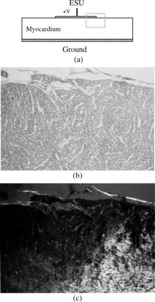
Figure 11 illustrates the loss of birefringence at elevated temperatures in cardiac muscle. Figure 11a shows a circular disk active electrode applied to the epicardial surface
Figure 11. Disk electrode applied to myocardium. (a) Geometry.
(b) Light microscopic view of region in dashed rectangle at the edge of the electrode. Original magnification 40 . (c) Transmission Polarizing Microscopy (TPM) view of the same section showing the clear delineation of the zone of birefringence loss. Original magnification 40 .
ELECTROSURGICAL UNIT (ESU) |
167 |
of excised myocardium. The ground plane is applied to the endocardial surface. Figure 11b is a light microscopic (LM) view of the histologic section at an original magnification of 10 stained with hematoxylin and eosin. Figure 11c is the corresponding Transmission Polarizing Microscopy (TPM) view of the same section. The views are taken from the region shown in dashes at the outer edge of the disk electrode. While the boundary of thermal damage can just be identified by a skilled observer in the LM image (Fig. 11b), a clear line of demarcation is visible in the TPM image (Fig. 11c). For heating times in the range of 1–2 min useful estimates of the kinetic coefficients are E ¼ 1.45 105 (J mol 1) and A ¼ 12.8 1021 (s 1). These coefficients give erroneous predictions for heating times outside of this range, however.
Birfringence loss identifies irreversible major structural damage in the cardiac myocyte. It is certainly arguable that electrophysiologic function is probably lost at lower temperatures than the 50þ 8C required to achieve the result shown in the figure. However, clinically, the 50 8C isotherm seems to correspond with the desired result (30), and also with the birefringence loss boundary for heating times in this range (31).
Tissue Fusion and Vessel Sealing. Irreversible thermal alteration of collagen is apparently the dominant process in coagulation and successful tissue fusion (32–34). Electron microscopic (EM) studies suggest that the end-to-end fusion process in blood vessels is dominated by random reentwinement of thermally dissociated adventitial collagen fibrils (Type I) during the end stage heating and early cooling phases (34). Successful vessel seals depend on the fusion of intimal surface tissues and the support provided by thermal alteration of medial and adventitial tissues.
Collagen is a ubiquitous tissue structural protein consisting of three left-hand a-helices wound in a rope-like molecular form (Fig. 12) with a periodicity of 68 nm (35). In this figure a small segment of a typical 300 nm long molecule is shown. The 300 nm molecules spontaneously organize into quarter-staggered microfibrils 20–40 nm in diameter and these coalesce into larger diameter collagen fibers In situ. There are at least 13 different types of collagen fibers that form the structural scaffolding for all tissues, the most common are Types I, II, and III collagen. Collagen In situ is birefringent. One useful measure of irreversible thermal alteration in collagen is that when heated for sufficient time to temperatures in excess of60 8C the regularity of the fiber array is disrupted and collagen loses its birefringent property (see Fig. 13). When viewed through the analyzer, native state collagen shows up as a bright field due to its birefringent properties. Thermally damaged collagen loses this property and is dark in the field. The kinetic coefficients for collagen birefringence loss in rat skin are (36): A ¼ 1.606 1045 (s 1) and E ¼ 3.06 105 (J mol 1). The birefringence-loss damage process in collagen has a critical temperature of 80 8C. These coefficients have proven useful over a wide range of heating times from milliseconds to hours.
Collagen shrinks in length as well as losing its organized regular rope-like arrangement of fibers. A model for

168 ELECTROSURGICAL UNIT (ESU)
Figure 12. Sketch of periodic structure of the 1 2 3 basic collagen molecule.
collagen shrinkage obtained by Chen et al. (37,38) is a bit different in style from the first-order kinetic model. They measured shrinkage in rat chordae tendonae over several orders of magnitude in time for temperatures between 65 and 90 8C and under different applied stresses. They were able to collapse all of their measured data into a single curve, sketched approximately in Fig. 14. In their experiments an initial ‘‘slow’’ shrinkage process (for equivalent exposure time < t1) is followed by a rapid shrinkage rate (t1 < t < t2) and a final slow shrinkage process. The practical maximum for shrinkage in length, j (%), is 60%. Longer equivalent exposures result in gellification of the collagen and complete loss of structural properties. After initial shrinkage, the collagen partially relaxes during cooling, indicated by the shrinkage decay region in Fig. 14. The curve fit functions utilize a nondimensional time axis, t/t2, where the fit parameters are expressed in the form of the logarithm of the time ratio:
n ¼ ln t ð3Þ t2
The shrinkage is obtained by interpolation between the two slow region curves (through the fast region):
j ¼ ð1 f ðnÞÞ½a0 þ a1n& þ f ðnÞ½b0 þ b1n& |
ð4Þ |
where a0 ¼ 1.80 2.25; a1 ¼ 0.983 0.937; b0 ¼ 42.4 2.94; and b1 ¼ 3.17 0.47 (all in %). The best-fit interpolation function, f(n), is given by
f ðnÞ ¼ |
eaðn nmÞ |
ð5Þ |
|
1 þ eaðn nmÞ |
|
||
where a ¼ 2.48 0.438, and nm ¼ ln{t1/t2} ¼ |
0.77 0.26. |
||
Finally, at any temperature t2 is given by |
|
||
t2 ¼ e½aþbPþM=T& |
ð6Þ |
||
where a ¼ 152.35; b ¼ 0.0109 (kPa 1); P ¼ applied stress (kPa); and M ¼ 53,256 (K).
68 nm
The functional form of t2 contains the kinetic nature of the process, but is in the form of an exposure time rather than a rate of formation, as was used in Eq. 2, and so the coefficient, M, is positive. To use the collagen shrinkage model, the shrinkage is referred to an equivalent t2. That is, at each point in space and time an equivalent value for the increment in t/t2 is calculated and accumulated until shrinkage is calculated.
A representative clinical application of collagen shrinkage is the correction of hyperopia using rf current, termed Conductive Keratoplasty. In this procedure a small needle electrode is inserted into the cornea to a depth of just over one-half of the thickness (see Fig. 15a). A teflon shoulder controls the depth of insertion. The speculum used to retract the eyelids comprises the return electrode in this procedure (Fig. 15b). The RF lesions are placed at 458 increments on circumferences with diameters of 6, 7, or 8 mm—8, 16, or 24 lesions depending on the degree of curvature correction (i.e., diopter change) required (Fig. 15c). Pulsed RF current heats and shrinks the corneal collagen to decrease the circumference and thus the radius of curvature of the cornea. Figure 16 is a histologic crosssection of a typical lesion seen a few minutes after its creation. Figure 16a is a light microscopic section (hematoxylin and eosin stain) and Fig. 16b is the corresponding transmission polarizing microscopy section showing the loss of collagenous birefringence near the electrode path. The effect of shrinkage on the collagen fibers is clearly visible as the normal fibrous wave is stretched in the vicinity of the electrode site (Fig. 16b).
A representative example of tissue fusion processes is the sealing of blood vessels by fusion of the intimal surfaces. In this application, forceps electrodes grasp the vessel and a bipolar rf current is used to heat and fuse the tissue (Fig. 17). An example experimental result is shown in Fig. 18, where a successful seal was obtained In vivo in a femoral artery. In that experiment a thermocouple was advanced through the vessel to the site of the electrodes, accounting for the hole in the cross-section.
Figure 13. Vessel collagen birefringence loss. (a) Thermally fused canine carotid artery, H&E stain (Original magnification 40 ). (b) TPM view of same section showing loss of birefringence in adventitial collagen under bipolar plate electrodes.

60
x (%)
t1 |
t2 |
Time (log scale) |
Figure 14. Collagen shrinkage model curve (38). [Reproduced with permission from ‘‘Corneal reshaping by radio frequency current: numerical model studies’’ Proc. SPIE v4247 (2001) pp 109–118.]
Sealing and fusion of vessels by electrosurgical current is strongly influenced by the inhomogeneous architecture of the tissue constituents, particularly in the large arteries. Inhomogeneities in electrical properties of the constituents, specifically smooth muscle, collagen and elastin, lead to sharp spatial gradients in volumetric power deposition that result in uneven heating. The mechanical properties of the various tissue constituents are also of considerable importance. Vascular collagen and elastin distribution varies from vessel to vessel, species to species in the same vessel, and point to point in the same vessel of the same species.
ELECTROSURGICAL UNIT (ESU) |
169 |
Cutting Processes
The essential mechanism of cutting is the vaporization of water. Water is by far the most thermodynamically active tissue constituent. Its phase transition temperature near 100 8C (depending on local pressure) is low enough that vaporization in tissue exerts tremendous forces on the structure and underlying scaffolding. The ratio of liquid to vapor density at atmospheric pressure is such that the volume is multiplied by a factor of 1300 when liquid water vaporizes. Expansion of captured water is capable of disrupting tissue structure and creating an incision. The goal in electrosurgical cutting is to vaporize the water in a very small tissue volume so quickly that the tissue structure bursts before there is sufficient time for heat transfer to thermally damage (coagulate) surrounding tissues (39). The same strategy is used in laser cutting.
Cutting electrodes have high rates of curvature to obtain the high electric fields necessary to accomplish cutting. The electrodes are not generally sharp, in a tactile sense, but the edge electrical boundary conditions are such that extremely strong electric fields result. With the possible exception of needle electrodes, the scalpel electrodes of Figs. 1 and 2 are not capable of mechanically damaging tissues. The intense electric fields vaporize tissue water
Figure 15. Needle electrode used to shrink corneal collagen and change curvature for correction of hyperopia.
(a)Cross-section of electrode in place,
(b)View of speculum return electrodes,
(c)spot pattern for shrinkage lesion location. [Reproduced with permission from ‘‘Corneal reshaping by radio frequency current: numerical model studies’’ Proc. SPIE v4247 (2001) pp109–118.]

170 ELECTROSURGICAL UNIT (ESU)
Figure 16. Histologic view of collagen shrinkage for Conductive Keratoplasty. (a) Light microscopic view, hematoxylin, and eosin stain.
(a) The TPM view, same section. Original magnification 40 .
ahead of the electrode, and the tissue structure parts due to internal tension to allow the electrode to pass essentially without tissue contact. Certainly, if the surgeon advances the electrode too quickly there is a dragging sensation due to perceptible friction, and much more radiating thermal damage around the incision site.
Good cutting technique requires matching the generator output characteristics (primarily the source impedance, but also to some extent the fundamental frequency), open circuit voltage setting, electrode shape and cutting speed to optimize the surgical result. Continuous sine waves are more effective for cutting than interrupted waveforms since the time between vaporization episodes is so much shorter that radiating heat transfer is virtually eliminated. Well-hydrated compartmentalized tissues, like skeletal muscle or gingiva, cut more cleanly than drier tissues, such as skin. Higher fundamental frequencies seem to give cleaner cuts than lower frequencies, but the reason for this is not known.
ADVANCED PRINCIPLES OF ELECTROSURGERY
Hazards of Use and Remedies
Any energy source, including electrosurgery, has hazards associated with its use. The goal of the user is to achieve safe use of the device by minimizing the risk. While it is not possible to completely eliminate hazards, it is possible by
careful technique to reduce them to acceptable levels. Several of the common hazards associated with electrosurgery are alternate site burns, explosions, stimulation of excitable tissues, and interference with monitoring devices and pacemakers. The RF currents are designed to thermally damage tissues, so the possibility of alternate site burns (at sites other than the surgical site) is always present. Explosions of combustible gases were, and still are, a hazard of electrosurgery. Combustible gases include at least two relatively little-used anesthetic agents (ether and cyclopropane) and bowel gas, which has both hydrogen and methane, as a result of bacterial metabolism. Arcs and/or sparks are routinely generated when cutting tissue so there is always an ignition source for a combustible mixture. While the fundamental frequency of electrosurgery is above the threshold for stimulation, arcs or sparks generate low frequency components that can stimulate electrically excitable tissues, that is, muscle and nerve. Radiated rf in the operating room and rf currents in the tissues posed few problems in early days, unless a faulty ground or other machine fault led to a burn at some alternate site. In the present day, electrosurgery raises considerable havoc with instrumentation amplifiers, pacemakers, and other electronic measurement
Figure 17. Bipolar forceps electrodes for vessel sealing.
Figure 18. Histologic cross-section of a vessel sealing experiment in the canine femoral artery. Successful seal obtained with a center temperature of 89 8C for 2 s. Hole in center of section is location of thermocouple used to monitor temperature. Original magnification 40 .

devices. Because so many potentially current-carrying objects and devices are now routinely attached to the patient, the attendant hazards have increased.
The remarkable feature of electrosurgical accidents is that, although they are rare (one estimate puts the probability at 0.0013%, or 200 out of 15 million procedures using electrosurgery, on an annual basis) they are usually a profound and traumatic event for the patient and the surgical team, and often cause for expensive litigation. The non-surgeon might reasonably wonder, in the light of the problems, why electrosurgery is used. The answer is that the tremendous advantages achieved by the use of electrosurgery (the remarkable reduction in morbidity and mortality and the low cost compared to competing technologies) make it a very effective technology for use in clinical medicine. It is important to note that hazards attend any energy source (and electrosurgery is one among several in the operating room) and they can be reduced and managed, but not eliminated. Clever application of appropriate technology can make considerable contributions in this area by reducing device interactions.
Alternate Site Burns
Electrosurgical units in general have very high open circuit output voltages that may appear at the scalpel electrode when it is not in contact with the tissue. When current is flowing the scalpel voltage is much reduced. Standard vacuum tube electrosurgery units may have open circuit voltages approaching 10,000 V peak-to-peak. This high open circuit output voltage is very effective in the initiation of fulguration techniques and in the spray coagulation of large tissue segments, which makes these units popular for certain procedures, especially in urologic surgery. However, the high voltages at the scalpel electrode also can initiate arcs to other objects, and must be handled with caution. This can be an especially difficult problem in minimally invasive surgery through an endoscope since the surgeon’s field of view may be limited. The solid-state electrosurgery units usually have lower maximum output voltages (somewhere in the range of 1000–5000 V peak-to- peak depending on design) the exception being recent designs based on HEXFET or VMOS technology, which approach the open circuit voltage of vacuum tube devices.
ELECTROSURGICAL UNIT (ESU) |
171 |
All electrosurgery units have output voltages that are potentially hazardous.
It is prudent to inspect all surgical cables periodically for damage to the insulation: especially those that are routinely steam sterilized. While in use, it is not a good idea to wrap the active cable around a towel clamp to stabilize it while accomplishing cutting or coagulation: The leakage current to the towel clamp will be concentrated at the tips of the towel clamp and may cause a burn. One should not energize the electrosurgical unit when the scalpel is not being used for cutting or coagulating. This is because when not using electrosurgery, the full open circuit voltage is applied between the active and return electrode cables, and one runs the risk of inadvertent tissue damage. Care should be taken to ensure that an unused scalpel electrode is not placed in a wet environment during surgery. The leakage current of any scalpel electrode may be increased by dampness. Additionally, some of the hand control designs can be activated by moisture at the handle. In one recent case, a hand control scalpel was placed on the drape in between activations. The scalpel was in a valley in the drape sheet in which irrigating fluid collected. The pooled fluid activated the electrosurgery machine and a fairly severe steam or hot water burn resulted on the patient’s skin.
The high voltages and frequencies typical of electrosurgery make it essential to use apparatus with insulation of good integrity. It should also be kept in mind that the electric fields extend for some distance around cables in use at high voltage. An effort should be made not to have active and return electrode cables running parallel to each other for any distance in order to reduce the capacitive coupling between them, unless the apparatus is specifically deigned to be used this way, as in bipolar device cables.
There is an additional problem in monopolar endoscopic surgery that must be addressed. It arises when a metal laparoscope with an operating channel is isolated from a voltage reference plane, as depicted in Fig. 19. In this case, the insulating skin anchor isolates the metal laparoscope (or metallic trochar sleeve) so that its potential is determined by parasitic capacitances between the metallic elements. The resulting circuit creates a capacitive voltage divider, diagrammed in Fig. 20. The two parasitic capacitances are unavoidable. The voltage divide ratio for this
Figure 19. Diagram of isolated laparoscope with active operating channel.

172 |
|
|
ELECTROSURGICAL UNIT (ESU) |
|
|||
|
|
|
|
|
|
|
|
|
|
|
C1 |
|
|
|
|
|
|
|
|
|
|
|
|
|
|
|
Scalpel to laparoscope |
|
|
||
|
+ |
: Voltage on laparoscope |
|||||
|
|
|
V L |
||||
|
|
|
ESU |
||||
|
- |
|
|
||||
|
|
|
|
|
|
||
|
|
|
C2 |
|
|
|
|
|
|
|
|
|
|
|
|
|
|
|
Laparoscope to tissue |
|
|
|
|
|
|
|
|
|
|
|
|
Figure 20. Equivalent capacitive voltage divider circuit for isolated laparoscope with active operating channel.
equivalent circuit is
C1 |
ð7Þ |
VL ¼ C1 þ C2 |
The parameter C1 is always quite a bit larger than C2, and the surface potential on the laparoscope, VL, may be as much as 80–90% of the surgical voltage. This induced voltage is capable of generating sparks to the surrounding tissues out of the field of view of the surgeon. Several cases of distributed severe burns have resulted from situations similar to this. There are two remedies. First, the operating laparoscope may be grounded. This does not eliminate the C1 capacitance, so there will be capacitively coupled currents between the scalpel electrode and the laparoscope. However, the laparoscope will be at zero potential. The second approach involves monitoring the scalpel electrode and return electrode currents. If they are substantially different then a hazard situation exists. There is at least one commercial device designed to do this.
Explosions. The original explosion hazard in the operating room arose from the use of explosive anesthetic agents, such as ether and cyclopropane. Combustible mixtures of these gases can be ignited by any arc discharge of sufficient energy—by static discharges between personnel and grounded objects, by arcs due to power switch openings in mains-powered devices, and by electrosurgical arcs at the cutting site. A few early instances of explosions and ensuing fires in operating rooms stimulated the establishment of requirements for operating room construction and use to lessen this hazard. In particular, operating rooms in the United States were required to have semiconducting flooring that was to be checked periodically for conductivity; operating room personnel were required to wear conductive shoe covers that would drain off accumulated static charge to the conductive flooring; and explosionproof switches and plugs were required below the five foot level where the relatively heavy combustible gases might collect. Also, surgical table coverings and fixtures are connected to ground through moderate impedance in order to prevent static accumulation. These requirements greatly reduced the explosion risk in the operating room, but lead to some rather amusing non sequiturs. For example, it makes little sense to attach an explosion-proof foot switch to an electrosurgical generator (particularly to a spark gap oscillator) since arcing is inherent to the use of electrosurgery. Of course, since the wall plugs for mains power were required to be explosion proof, the power line plug on the generator was also often explosion proof. Because of the inordinate expense of explosion proof construction and the
rare use of combustible gases, the majority of new operating room construction is designed to satisfy the requirements for oxygen use only and specifically designated not for use of explosive gases.
There are, however, other explosion–combustion sources. Two constituents of bowel gas are combustible, hydrogen and methane, and there is almost always sufficient swallowed air to comprise an explosive mixture. Approximately 33% of the adult population are significant methane producers due to the indigenous gut flora and fauna responsible for certain aspects of digestion. One preventive measure that has been used is insufflation of the bowel with carbon dioxide, or some other inert gas, during electrosurgery. A large volume of CO2 will dilute and displace the combustible mixture, reducing the chance of explosion.
Additionally, care must be taken in pure oxygen environments not to ignite organic materials. Body hair has been ignited in a pure oxygen environment by an electrosurgical arc. In surgery on the larynx, both electrosurgery and CO2 lasers have ignited plastic endotracheal tubes and surgical gloves in the oxygen-rich environment.
Stimulation of Electrically Excitable Tissues. The stimulation of motor nerves is a well-known phenomenon accompanying electrosurgery. Stimulation of the abdominal muscles is often observed, and the obturator nerve bundle (connecting the spinal column to the leg) is also quite often stimulated. Obturator nerve stimulation is inherent to transurethral resections, and the resulting movement is always undesirable. Part of the stimulation problem arises from the low frequency components of the surgical arc, and part from the confinement of current. For example, the obturator nerve is clustered with the major blood vessels supplying the leg (iliac/femoral artery and vein) and emerges from the pelvis under the inguinal ligament into the upper thigh area. The pelvic bone structures are essentially nonconductive and impede current flow. The nerve– artery–vein cluster represents a relatively high conductivity pathway of small cross-section between the abdomen and the upper thigh, a typical location for the return electrode. As such, the surgical current in TURP procedures is somewhat concentrated in that tissue cluster, and stimulation is often observed. In the case of general abdominal surgery, the majority of surgical current flows in the surface tissue structures, reducing the likelihood of obturator stimulation. In the case of transurethral resections, the current source is deep in the floor of the abdomen, and the surface tissues carry a smaller fraction of the total surgical current. The very high currents in TURPs and the frequent use of spark gap oscillators means that an abundant supply of intense low and high frequency signals is contained in the surgical current. It is a personal observation that motor unit stimulation is closely correlated with relatively intense arc strikes while accomplishing cutting or coagulating. This is to be expected from the frequency spectrum of the surgical signals.
There are, in addition, several reported instances of ventricular fibrillation induced by electrosurgery (40–43). The low frequency arc components and high intensity high frequency signals are capable of stimulating

excitable tissues, with ventricular fibrillation as a possible outcome.
Interference with Instrumentation. The cutting current generated by standard oscillators, such as the vacuum tube and solid-state devices, has a well defined, narrow bandwidth. When an arc is struck at the surgical site, extensive signal energy is added at the high frequency end and at the low frequency end of the spectrum. Signals from spark gap oscillators have these components whether or not an arc is established at the tissue. Over the range of physiological frequencies the arc components are of very low amplitude compared to the generator fundamental frequency; but since the surgical currents and voltages are very high, the arc components may be many times larger than physiological signals such as the ECG. This creates a considerable problem for all measuring instruments including demand, or noncompetitive, pacemakers. There are many reported instances of inhibition of demand pacemakers by electrosurgery (44–47).
The population most at risk for pacemaker inhibition is patients undergoing either open heart surgery or transurethral resections of the prostate. Open heart operations put the electrosurgical scalpel electrode in close proximity to the pacemaker electrodes. The TURPs use the highest currents and voltages, and the interference signals are potentially large at the pacemaker electrodes. There is some indication that a higher incidence of prostate problems is associated with long-term pacemaker implantation, so it is to be expected that this problem will continue. The present use of shielded pacemakers virtually eliminates microwave sensitivity, but not electrosurgical effects.
All pacemakers may be damaged to failure by electrosurgery signals, and some caution should be observed when performing electrosurgery in the presence of pacemakers. Bipolar electrosurgery is much less likely than monopolar to cause interference with pacemakers because the surgical current field is confined and the voltages are low. There are many techniques for which bipolar electrosurgery is unacceptable, however, so monopolar methods must be used. In those cases, care should be exercised to encourage the surgical current field to avoid the right ventricle. To the extent that is practical, elevate the pacing electrode site (either the right ventricular wall or the external surface) away from the conductive fluids and tissues when cutting near the heart. Place the dispersive electrode on the left side of the body (this will only help a little bit). Anticipate some form of pacemaker malfunction.
Representative Electric Field Distributions
The effect of rf current on tissues is to heat them according to the first law of thermodynamics:
rtct |
@T |
¼ r ðkrTÞ þ qgen þ qm þ wtcbðTa |
TÞ |
hfg |
@m |
|||||||||||
|
|
|
||||||||||||||
@t |
@t |
|||||||||||||||
|
|
|
|
|
|
|
|
|
|
|
|
|
|
ð8Þ |
||
where r¼ density (kg m |
3), c ¼ specific heat (J kg 1 K 1), |
|||||||||||||||
T ¼ |
|
|
|
1 |
|
1 |
|
¼ |
time (s), k |
¼ |
thermal conducti- |
|||||
|
temperature (K), t |
|
|
|||||||||||||
vity (W |
m |
|
K |
), |
qgen ¼ externally |
applied |
rf power |
|||||||||
(W m |
3 |
|
|
3 |
|
w ¼ perfusion |
||||||||||
), |
qm ¼ metabolic heat (W m |
|
), |
|||||||||||||
ELECTROSURGICAL UNIT (ESU) |
173 |
Figure 21. Geometry for infinite flat plate electrode calculation.
(kgb kgt 1 s 1), hfg ¼ vaporization enthalpy (J kg 1) and dm/dt is the mass rate of vaporization (kg s 1). Each term in the relation has units of (W m 3) and the t subscript refers to tissue, while the b subscript refers to blood properties. This form does not include vaporization processes typical in cutting. Typically, both metabolic heat and perfusion heat transfer are negligible in electrosurgery. It is important to note that all of the tissue properties are dependent on the water content. As tissue dries out the density, electrical, and thermal conductivity decrease. As temperature rises the electrical conductivity increases1–2%/8C, until drying at higher temperatures causes a decrease.
At electrosurgical frequencies the quasistatic assumption applies (simplifying calculations) and heat dissipation is dominated by joule, or resistive, heating (W m 3):
q |
gen ¼ |
E |
|
J |
¼ |
s |
E |
j |
2 |
¼ |
jJj2 |
9 |
Þ |
|
|||||||||||||
|
|
|
j |
|
|
s |
ð |
where E ¼ electric field vector (V m 1), J ¼ current density vector (A m 2), and s ¼ electrical conductivity (S m 1). This section reviews several representative electric field distributions.
Simple Field Geometries: Analytical Solutions. The simplest case is that of the electric field between parallel plates (Fig. 21). For a uniform medium between the plates the electric field is uniform (i.e., V increases linearly from V2 to V1) and is equal to the voltage difference divided by the distance between the plates: (V1 V2)/d ¼ DV/d. It points from the higher potential (V1) to the lower potential (V2). In
this case the heating term, qgen, is also simple: qgen ¼ s DV2/ d2. For an operating voltage difference of 50 V(rms) and
plate separation distance of 2 cm, the electric field is 2500 (V m 1), and if the electrical conductivity is 0.3 (S m 1) the power density would be 1.88 W cm 3.
Another simple analytical solution is for the case of coaxial cylinders (Fig. 22). In this geometry the potential increases as the natural log of the radius from V2 to V1, and the electric field (pointing in the radial direction) is given by
E ¼ |
IL |
ar |
ð10Þ |
2psr |
where IL ¼ the current per unit length of coaxial structure (i.e., length into the page, A m 1). For this geometry the rf power generation decreases as 1/r2:
|
IL |
2 |
1 |
|
|
|
|
|
|||
qgen ¼ E J ¼ s |
|
|
|
|
ð11Þ |
2ps |
|
r2 |
|||

174 ELECTROSURGICAL UNIT (ESU)
Figure 22. Geometry for coaxial cylinder electrode example. The outer cylinder typically comprises the return electrode, V2 ¼ 0.
For a center cylinder electrode 2 mm in diameter and outer cylinder 2 cm in diameter and tissue electrical conductivity 0.3 (S m 1), the overall conductance per unit length would be G ¼ 0.816 (S m 1)— that is, G ¼ 2s/ (ln{b/a}). At a voltage difference of 50 V(rms), the current per unit length would be IL ¼ 40.9 (A m 1) and maximum electric field 21.7 (kV m 1) at r ¼ 1 mm. The maximum volume power density would be 142 W cm 3 at r ¼ 1 mm in this example.
These examples are useful in understanding simple surgical fields. The uniform electric field case is not very different from that obtained near the center of a bipolar forceps electrode used to coagulate a tissue volume. The coaxial case is close to the electric field around a needle electrode as long as one is not too close to the tip. In both cases the analytical field expressions are simple because the boundaries are parallel to Cartesian and cylindrical coordinates, respectively. Also, the boundaries are chiefly isopotential, or Dirichlet, boundaries.
Disk Electrode Field. The electric field around a disk electrode applied to a large volume of tissue is a much more complex geometry (Fig. 23). This geometry was solved analytically by Wiley and Webster (48) for the V ¼ 0 reference electrode located at r ¼ þ1 and z ¼ 1. The electrode is an isopotential surface (@V/@r ¼ 0) and the air is insulating (zero flux, @V/@z ¼ 0); and at the edge of the disk (r ¼ a) the field must satisfy two mutually exclusive boundary conditions. The consequence is that the electric field and current density both increase without bound at
Figure 23. Solution geometry for disk electrode applied to infinite medium. Return electrode, V ¼ 0, located at r ¼ 1 and z ¼ 1.
|
2.0 |
|
|
|
|
|
(r,0) |
1.5 |
|
|
|
|
|
|
|
|
|
|
|
|
z |
|
|
|
|
|
|
J |
|
|
|
|
|
|
Normalized |
1.0 |
|
|
|
|
|
0.5 |
|
|
|
|
|
|
|
|
|
|
|
|
|
|
0.0 |
|
|
|
|
|
|
0.0 |
0.2 |
0.4 |
0.6 |
0.8 |
1.0 |
|
|
|
Normalized Radius (r/a) |
|
|
|
Figure 24. Normalized surface current density under the electrode from r ¼ 0–0.95a.
the electrode edge, r ¼ a (48):
Jzðr; 0Þ ¼ |
J0 |
ð12Þ |
2h1 ðr=aÞ2i1=2 |
where J0 ¼ I/pr2, the average current density. Figure 24 plots the normalized surface current (J0 ¼ 1) density versus normalized radius under the electrode. For radii less than0.89a the current density is less than the average value. This is at first glance an alarming result: It is not obvious why burns do not result at the edge of every electrode. There are three mitigating factors. First, the singularity at r ¼ a is an integrable singularity—meaning that one may integrate Jz(r,0) from r ¼ 0 to r ¼ a and get a finite result (i.e., integral {Jz dA} ¼ I, the total current). Second, actual electrodes do not have mathematically sharp edges, but rather are filleted. Third, heat transfer dissipates the temperature rise at the edge and even though qgen increases without bound (in a microscopic sense) the temperature rise at the edge reaches a finite maximum—still much higher than that at the center of the electrode, however.
The electric fields near a disk electrode, such as that used to ablate myocardium (Fig. 11) is very similar to the analytical solution. Figure 25 is the result of a quasi static Finite Element Method (FEM) calculation for the geometry used to create Fig. 11. The assumed electrode potential is 50 V(rms), and the isopotential lines (25a) are not significantly different in shape from those of the analytical solution (48). The electric field (current density lines) lines (Fig. 25b) are very crowded at the edge of the electrode, as expected from the above discussion. The result is that the volume power density, qgen, (Fig. 25c) is higher by a factor of 1000 or more (see the 12 W cm 3 contour) than about one electrode radius away (cf. to the 0.062 W cm 3 contour).
Needle Electrode Field. Needle electrodes are often used to desiccate or coagulate small lesions. They are also used to shrink corneal collagen to change its curvature, as was discussed above (in the section Ablation, Coagulation and Tissue Fusion). The electric field around the tip of such an electrode is extremely high compared to the average value.
ELECTROSURGICAL UNIT (ESU) |
175 |
For comparison, the electric field and corresponding volume power density field were calculated around a needle electrode in cornea: Cornea electrical conductivity, at 1.125 S m 1, is quite a bit higher that the 0.3 S m 1 assumed for muscle in previous calculations. An electrical conductivity of 1.5 S m 1 was assumed for the aqueous humor, accounting for the discontinuity in the constant power density contours at the interface. The results are shown in Fig. 26 for an assumed electrode potential of
50V(rms).
Note that the volume power densities are extremely
high compared to the disk electrode calculation due to the small dimensions of the needle electrode. Power densities of 100 kW cm 3 have adiabatic (no heat transfer) heating rates near 27,000 8C s 1 and will vaporize significant amounts of water in microseconds. In practice, the applied voltage is in the neighborhood of 50–80 V (rms), however, pulsed rf is used with pulse times in the neighborhood of 15 ms. Vaporization begins during the first rf pulses in a very small volume around the electrode tip. Subsequent drying near the tip causes the dominant heat-
Figure 25. Circular disk electrode FEM model results. Muscle conductivity 90.3 S m 1. (a) Potential field, V(r,z). (b) Electric field streamlines.
(c) Volume power density with contours at 0.062, 0.86, and 12 W cm 3.
ing field to advance from the tip toward the surface while the overall impedance decreases due to an average increase in temperature around the electrode. At the higher voltage settings the heating may be sufficient to cause the impedance to increase near the end of rf activation due to drying in the cornea (49).
Bipolar Forceps Electrode Field. The bipolar forceps electrodes typically used in vessel sealing are essentially flat plate electrodes. The electric field between them is nearly uniform, with some small electrode edge effect. Figure 27 is a representative FEM calculation assuming an applied potential of 50 V(rms) and electrode separation of 2 mm. Here the power densities are in the neighborhood of 150–200 W cm 3. The calculations have again assumed a uniform electrical conductivity of 0.3 S m 1 while the actual value is a complex combination of collagen (s ¼ 0.26–0.42 S m 1 depending on orientation), elastin
(s ¼ 0.67–1.0 S m 1 depending on orientation) and smooth muscle (s ¼ 0.3 S m 1).
Figure 26. Needle electrode in cornea, FEM model results. Cornea conductivity 1.125 S m 1, aqueous humor 1.5 S m 1. (a) Potential field V(r,z) for 50 V (rms) electrode potential. (b) Electric field streamlines. (c) Volume power density with contours at 115, 3.2, and 0.098 kW cm 3.

176 ELECTROSURGICAL UNIT (ESU)
Figure 27. Bipolar forceps applied to a vessel, FEM model results.
(a) Potential field, V(x,y) for 50 V(rms) electrode potential. (b) Electric field streamlines. (c) Volume power density, qgen, with contours at 85, 193, and 443 (W cm 3). (d) Typical result: canine femoral artery temperature 89 8C for 2 s (thermocouple in center of artery; original magnification 40 , Mallory’s trichrome stain).
SUMMARY
Radio frequency current has been used for many years to reduce time under anesthesia and improve the clinical result. The ability to simultaneously cut tissue and coagulate blood vessels greatly reduces morbidity and mortality, and enables a large number of procedures that are otherwise not possible, especially in neurosurgery. Electrosurgery is one of several energy sources making substantial contributions in surgery, sources that include: lasers, microwaves, ultrasound, micromechanical disruption, and cryogenics. The major advantage of electrosurgery over the other modes originates from its ability to shape the treated tissue volume by design of the applicator electrode geometry alone. Consequently, a single electrosurgical generator is capable of a wide range of applications from various forms of coagulation and tissue fusion to cutting, either through an endoscope or in open procedures, either microsurgery or, as it were, macrosurgery. Since the
electrodes are in contact with tissue, apposition pressure may be applied to improve the fusion probability. Electrode contact also gives the surgeon tactile feedback not characteristic of many of the other energy sources.
Useful predictions of clinical outcomes may be made with quasistatic electric field models coupled to transient thermal models including kinetic formulations of damage accumulation. Numerical model work can be used (1) to study trends due to uncertainty in tissue properties or changes in electrode voltage, current, power, or time of application; (2) to reveal discontinuities in the electric field due to boundary, conditions; and (3) to study the relative importance of each of the governing physical phenomena individually. When trends in the model match experimental results, one knows that all of the relevant physical phenomena have been included and the surgical process is well understood.
As with any such source of energy there are hazards in the use of electrosurgery. The hazards may be minimized, but not eliminated. Nevertheless, the advantages of use far outweigh the disadvantages, particularly in several very important procedures. The best safeguard is an informed and vigilant user population.
BIBLIOGRAPHY
Cited References
1.Major RA. History of Medicine Vols. I and II. Springfield (IL): Charles C. Thomas; 1954.
2.Breasted JH. The Edwin Smith Surgical Papyrus. Chicago: 1930.
3.Licht S. The history of therapeutic heat. Therapeutic Heat and Cold. 2nd ed. Elizabeth Licht; 1965. Chapt. VI.
4.Jee BS. A Short History of Aryan Medical Sciences. London: 1896.
5.Geddes LA, Roeder RA. DeForest and the first electrosurgical unit. IEEE Eng Med Biol Mag Jan/Feb 2003; 84–87.
6.Doyen E. Sur la destruction des tumeurs cancereuses accessibles; par la methode de la voltaisation bipolaire et de l’electro-coagulation thermique. Archg Elec Med Physiother Cancer 1909;17:791–795.
7.Doyen E. Surgical Therapeutics and Operative Techniques. Vol. 1. New York: Wm. Wood; 1917; p 439–452.
8.Moyer CA, Rhoads JE, Allen JG, Harkins HN. Surgery Principles and Practices. 3rd ed. Philadelphia: Lippincott; 1965.
9.Cushing H, Bovie WT. Electrosurgery as an aid to the removal of intracranial tumors. Surg Gyn Obstet 1928;47: 751–784.
10.Kelly HA, Ward GE. Electrosurgery. Philadelphia: Saunders; 1932.
11.Mitchell JP, Lumb GN, Dobbie AK. A Handbook of Surgical Diathermy. Bristol: John Wright & Sons; 1978.
12.Otto JF, editor. Principles of Minor Electrosurgery. LiebelFlarsheim Co.; 1957.
13.Harris HS. Electrosurgery in Dental Practice. Philadelphia: Lippincott; 1976.
14.Malone WF. Electrosurgery in Dentistry; Theory and Application in Clinical Practice. Springfield (IL): Chas C Thomas; 1974.
15.Oringer MJ. Electrosurgery in Dentistry. 2nd ed. Philadelphia: Saunders; 1975.
16.Oringer MJ. Color Atlas of Oral Electrosurgery. Chicago: Quintessence; 1984.