


1
Introduction
1.1 Objectives
This book addresses the problem of hardware synthesis from an initial, infinite precision, specification of a digital signal processing (DSP) algorithm. DSP algorithm development is often initially performed without regard to fi- nite precision e ects, whereas in digital systems values must be represented to a finite precision [Mit98]. Finite precision representations can lead to undesirable e ects such as overflow errors and quantization errors (due to roundo or truncation). This book describes methods to automate the translation from an infinite precision specification, together with bounds on acceptable errors, to a structural description which may be directly implemented in hardware. By automating this step, raise the level of abstraction at which a DSP algorithm can be specified for hardware synthesis.
We shall argue that, often, the most e cient hardware implementation of an algorithm is one in which a wide variety of finite precision representations of di erent sizes are used for di erent internal variables. The size of the representation of a finite precision ‘word’ is referred to as its word-length. Implementations utilizing several di erent word-lengths are referred to as ‘multiple word-length’ implementations and are discussed in detail in this book.
The accuracy observable at the outputs of a DSP system is a function of the word-lengths used to represent all intermediate variables in the algorithm. However, accuracy is less sensitive to some variables than to others, as is implementation area. It is demonstrated in this book that by considering error and area information in a structured way using analytical and semi-analytical noise models, it is possible to achieve highly e cient DSP implementations.
Multiple word-length implementations have recently become a flourishing area of research [KWCM98, WP98, CRS+99, SBA00, BP00, KS01, NHCB01]. Stephenson [Ste00] enumerates three target areas for this research: SIMD architectures for multimedia [PW96], power conservation in embedded systems [BM99], and direct hardware implementations. Of these areas, this book
21 Introduction
targets the latter, although Chapters 3 to 5 could form the basis of an approach to the first two application areas.
Throughout the book, both the word-length of operations, and the overflow methods used, are considered to be optimization variables for minimizing the area or power consumption of a hardware implementation. At the same time, they impost constraints on possible solutions on the basis of signal quality at the system outputs. The resulting multiple word-length implementations pose new challenges to the area of high-level synthesis [Cam90], which are also addressed in this book.
1.2 Overview
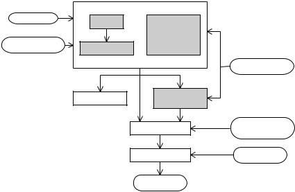
The overall design flow proposed and discussed is illustrated in Fig. 1.1. Each of the blocks in this diagram will be discussed in more detail in the chapters to follow.
|
(Chapter 3) |
(Chapter 5) |
|
Simulink |
signal |
combined |
|
|
scaling |
|
|
|
scaling |
|
|
|
|
|
|
|
|
and |
|
error |
wordlength |
wordlength |
|
constraints |
optimization |
|
|
optimization |
|
||
|
|
|
|
|
(Chapter 4) |
|
library |
|
|
|
|
|
|
|
cost models |
|
bit-true |
resource |
|
|
sharing |
|
|
|
simulator |
|
|
|
(Chapter 6) |
|
|
|
|
|
|
|
|
synthesis of |
multiple |
|
|
word-length |
|
|
|
structural HDL |
|
|
|
libraries |
|
|
|
vendor |
HDL |
|
|
synthesis |
libraries |
completed design
Fig. 1.1. System design flow and relationship between chapters
We begin in Chapter 2 by reviewing some relevant backgroud material, including a very brief introduction to important nomenclature in DSP, digital design, and algorithm representation. The key idea here is that in an e cient hardware implementation of a DSP algorithm, the representation used for each signal can be di erent from that used for other signals. Our representation consists of two parts: the scaling and the word-length. The optimization of these two parts are covered respectively in Chapters 3 and 4.
1.2 Overview |
3 |
Chapter 3 reviews approaches to determining the peak signal value in a signal processing system, a fundamental problem when selecting an appropriate fixed precision representation for signals.
Chapter 4 introduces and formalizes the idea of a multiple word-length implementation. An analytic noise model is described for the modelling of signal truncation noise. Techniques are then introduced to optimize the word-lengths of the variables in an algorithm in order to achieve a minimal implementation area while satisfying constraints on output signal quality. After an analysis of the nature of the constraint space in such an optimization, we introduce a heuristic algorithm to address this problem. An extension to the method is presented for nonlinear systems containing di erentiable nonlinear components, and results are presented illustrating the advantages of the methods described for area, speed, and power consumption.
Chapter 5 continues the above discussion, widening the scope to include the ability to predict the severity of overflow-induced errors. This is exploited by the proposed combined word-length and scaling optimization algorithm in order to automate the design of saturation arithmetic systems.
Chapter 6 addresses the implications of the proposed multiple word-length scheme for the problem of architectural synthesis. The chapter starts by highlighting the di erences between architectural synthesis for multiple wordlength systems and the standard architectural synthesis problems of scheduling, resource allocation, and resource binding. Two methods to allow the sharing of arithmetic resources between multiple word-length operations are then proposed, one optimal and one heuristic.
Notation will be introduced in the book as required. For convenience, some basic notations required throughout the book are provided in Appendix A, p. 151. Some of the technical terms used in the book are also described in the glossary, p. 153. In addition, it should be noted that for ease of reading the box symbol: is used throughout this book to denote the end of an example, definition, problem, or claim.
This page intentionally left blank