

AutoCAD 2005 For Dummies (2004)
.pdf30 Part I: AutoCAD 101
•A Default value or option appears in angled brackets: <>. To choose the default value or option, simply press Enter.
Observe the command line. You’ll discover a lot about how to use the command line simply by watching it after each action that you take. When you click a toolbar button or menu choice, AutoCAD types the name of the command automatically, so if you’re watching the command line, you’ll absorb the command names more-or-less naturally.
When AutoCAD types commands automatically in response to your toolbar and menu clicks, it usually adds one or two extra characters to the front of the command name.
•AutoCAD usually puts an underscore in front of the command name (for example, _LINE instead of LINE). The underscore is an Autodesk programmers’ trick that enables non-English versions of AutoCAD to understand the English command names that are embedded in the menus.
•AutoCAD sometimes puts an apostrophe in front of the command name and any underscore (for example, ‘_ZOOM instead of ZOOM). The apostrophe indicates a transparent command; you can run the command in the middle of another command without canceling the first command. For example, you can start the LINE command, run the ZOOM command transparently, and then pick up where you left off with the LINE command.
Leave the command line in the default configuration initially. The command line area, like most other parts of the AutoCAD screen, is resizable and relocateable. The default location (docked at the bottom of the AutoCAD screen) and size (three lines deep) work well for most people. Resist the temptation to mess with the command line area’s appearance — at least until you’re comfortable with how to use the command line.
Right-click in the command line area for options. If you right-click in the command line area, you’ll see a menu with some useful choices, including Recent Commands — the last six commands that you ran.
Press the upand down-arrow keys to cycle through the stack of commands that you’ve typed recently. This is another handy way to recall and rerun a command. Press the leftand right-arrow keys to edit the command line text that you’ve typed or recalled.
Main course: The drawing area
After all these screen hors d’oeuvres, you’re probably getting hungry for the main course — the AutoCAD drawing area. This is where you do your drawing, of course. In the course of creating drawings, you click points to specify locations and distances, click objects to select them for editing, and zoom and pan to get a better view of what you’re working on.

Chapter 2: Le Tour de AutoCAD 2005 |
31 |
AutoCAD is no vin ordinaire
The back and forth needed to get AutoCAD to draw and complete a line is a great example of AutoCAD’s power — and its power to confuse new users. It’s kind of like a wine that tastes a bit harsh initially, but that ages better than something more immediately drinkable.
In other programs, if you want to draw a line, you just draw it. In AutoCAD, you have to press Enter one extra time when you’re done just to tell AutoCAD you really are finished drawing.
But the fact that the Line command remains active after you draw the first line segment makes it much faster to draw complicated, multisegment lines, which is a common activity in a complex drawing.
This is just one example of how AutoCAD favors ease of use for power users doing complex drawings over ease of mastery for beginners, who frequently forget to hit Enter that extra time to close out a command.
Most of this book shows you how to interact with the drawing area, but you should know a few things up front.
The Model and Layout tabs (Model and Paper Space)
One of the initially disorienting things about AutoCAD is that finished drawings can be composed of objects drawn in different spaces, which AutoCAD indicates with the tabs along the bottom of the drawing area (Model, Layout1, and Layout2 by default).
Model space is where you create and modify the objects that represent things in the real world — walls, widgets, waterways, or whatever.
Paper space is where you create particular views of these objects for plotting, usually with a title block around them. Paper space comprises one or more layouts, each of which can contain a different arrangement of model space views and different title block information.
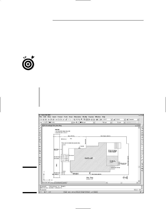
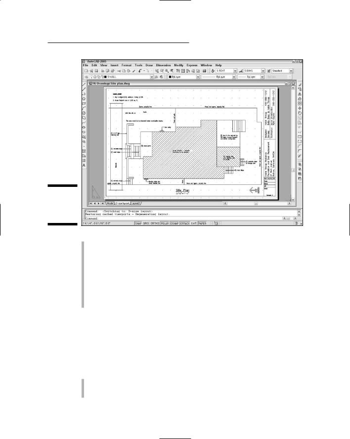
When you click the Model tab in the drawing area, you see pure, unadulterated model space, as shown in Figure 2-7. When you click one of the paper space layout tabs (Layout1 or Layout2, unless someone has renamed or added to them), you see a paper space layout, as shown in Figure 2-8. A completed layout usually includes one or more viewports, which are windows that display all or part of model space at a particular scale. A layout also usually includes a title block or other objects that exist only in the layout and don’t appear when you click the Model tab. (Think of the viewport as a window looking into model space and the title block as a frame around the window.) Thus, a layout displays model space and paper space objects together, and AutoCAD lets you draw and edit objects in either space. See Chapter 3 for information about creating paper space layouts and Chapter 12 for the lowdown on plotting them.
As I describe in the “Looking for Mr. Status Bar” section in this chapter, after you’ve clicked one of the layout tabs, the status bar’s MODEL/PAPER button
32 Part I: AutoCAD 101
moves the cursor between model and paper space while remaining in the particular layout. (As shown in Figures 2-7 and 2-8, the orientation icon at the lower-left corner of the AutoCAD drawing area changes between an X-Y axis for model space and a drafting triangle for paper space as an additional reminder of which space the cursor currently resides in.) Chapter 3 describes the consequences of changing the MODEL/PAPER setting and advises you on how to use it.
This back-and-forth with the MODEL/PAPER button or double-clicking is necessary only when you’re drawing things while viewing one of the paper space layouts. In practice, you probably won’t encounter that situation very often.
Instead, you’ll do most of your drawing on the Model tab and, after you’ve set up a paper space layout, click its layout tab only when you want to plot.
Drawing on the drawing area
Here a few other things to know about the AutoCAD drawing area:
Efficient, confident use of AutoCAD requires that you continually glance from the drawing area to the command line area (to see those all-important prompts!) and then back up to the drawing area. This sequence is not a natural reflex for most people. Get in the habit of looking at the command line after each action that you take, whether picking something on a toolbar, on a menu, or in the drawing area.
Figure 2-7:
Our model lounging around in model space.
Chapter 2: Le Tour de AutoCAD 2005 |
33 |
Figure 2-8:
Freshly laid out in paper space.
Clicking at random in the drawing area is not quite as harmless in AutoCAD as it is in many other Windows programs. When you click in the AutoCAD drawing area, you’re almost always performing some action — usually specifying a point or selecting objects for editing. Feel free to experiment, but look at the command line after each click. If you get confused, press the Esc key a couple of times to clear the current operation and return to the naked command prompt.
In most cases, you can right-click in the drawing area to display a menu with some options for the current situation.
A Palette-Cleanser
In AutoCAD 2005, two features called Properties and DesignCenter, a toolbarlike interface called Tool Palettes, and the new Sheet Set Manager appear in spiffy modeless dialog boxes, or palettes.
Properties and DesignCenter: Used to control object properties and named objects (layers, blocks, and so on), respectively. Chapter 4 shows you how.

34 Part I: AutoCAD 101
Tool Palettes: Resembles a stack of painter’s palettes, except that each palette holds content (drawing symbols and hatch patterns) and/or commands (toolbar-like macros — a new feature in AutoCAD 2005) instead of paints. Chapters 11, 13, and 15 help you unlock your inner Tool Palette artistry.
Sheet Set Manager: Provides tools for managing all of a project’s drawings as a sheet set. Chapter 14 gives you the lowdown on why you might
want to and how to do so.
You toggle these palettes on and off by clicking three buttons near the end of the Standard toolbar or by pressing Ctrl+1 (Properties), Ctrl+2 DesignCenter), Ctrl+3 (Tool Palettes), or Ctrl+4 (Sheet Set Manager). Figure 2-9 shows all four toggled on.
Modeless is just a fancy way of saying that these dialog boxes don’t take over AutoCAD in the way that modal dialog boxes do. Modal dialog boxes demand your undivided attention. You enter values, click buttons, or whatever, and then click the OK or Cancel button to close the dialog box. While the modal dialog box is open, you can’t do anything else in AutoCAD. A modeless dialog box, on the other hand, can remain open while you execute other commands that have nothing to do with the dialog box. You return to the modeless dialog box when or if you need its features.
Manipulating AutoCAD modeless dialog boxes — or palettes — is similar to manipulating a regular Windows dialog box, except that the title bar is along the side instead of at the top. In other words, you click and drag the title strip along the side to move the palette. If you experiment with the control buttons at the bottom of this strip (or right-click anywhere on the strip), you’ll quickly get the hang of what you can do with these palettes. In particular, turning on the auto-hide feature causes the dialog box to “roll up” into the strip so that it’s not taking up much screen space. When you point the cursor at the strip, the palette unfurls again.
Another cool feature — for the Tool Palettes but not the Properties and DesignCenter palettes — is transparency. Right-click the Tool Palettes’ title strip and choose Transparency to control this feature. With transparency turned on, you can see your drawing objects behind a faded version of the Tool Palettes. (According to my dictionary, that would make the palettes translucent, not transparent, but whatever.) If you combine transparency with auto-hide, you end up with Tool Palettes that have a low impact on your drawing area. And if you’re bothered by the amount of screen space taken by the command line area, you can make it transparent, too: Undock it, right-click the title bar and turn off Allow Docking, and then right-click again and choose Transparency. After you’ve set the transparency to your taste, click and drag the command line area to where you want it.

|
Chapter 2: Le Tour de AutoCAD 2005 |
35 |
|
Properties palette |
DesignCenter palette |
Tool palettes |
|
Figure 2-9:
A modeless menagerie.
What Really Makes AutoCAD Cook?
Knowing how to use the command line, as described in the section, “Take an order: The command line area,” is one of the secrets of becoming a competent AutoCAD user. In reading about and using AutoCAD, you encounter two additional topics frequently: system variables, which are AutoCAD’s basic control levers, and dialog boxes, many of which put a friendlier face on the system variables.
Sizzling system variables
System variables are settings that AutoCAD checks before it decides how to do something. If you set the system variable SAVETIME to 10, AutoCAD automatically saves your drawing file every ten minutes; if you set SAVETIME to 60, the time between saves is one hour. Hundreds of system variables control AutoCAD’s operations.

36 Part I: AutoCAD 101
Of these hundreds of system variables in AutoCAD, 70 system variables control dimensioning alone. (Dimensioning is the process of labeling objects with their lengths, angles, or special notes. Different professions have different standards for presenting dimensions on their drawings. Using dimensions is described in detail in Chapter 10.)
To change the value of a system variable, just type its name at the AutoCAD command prompt and press Enter. AutoCAD will display the current value of the system variable setting and prompt you for a new value. Press Enter alone to keep the existing setting, or type a value and press Enter to change the setting.
The procedure for entering a system variable is exactly the same as for entering a command name — type the name and press Enter. The only difference is what happens afterward:
A system variable changes a setting.
A command usually adds objects to the drawing, modifies objects, or changes your view of the drawing.
Being able to change system variables by typing their names at the command line is a boon to power users and occasionally a necessity for everybody else. The only problem is finding or remembering what the names are. In most cases, you’ll be told what system variable name you need to type — by me
in this book or by the local AutoCAD guru in your office.
To see a listing of all the system variables in AutoCAD and their current settings, use the following steps:
1.Type SETvar at the AutoCAD command prompt and press Enter.
AutoCAD prompts you to type the name of a system variable (if you want to view or change just one) or question mark (if you want to see the names and current settings of more than one):
Enter variable name or [?]
2.Type ? (question mark) and press Enter.
AutoCAD asks which system variables to list:
Enter variable(s) to list <*>:
3.Press Enter to accept the default asterisk (which means “list all system variables”).
AutoCAD displays the first 16 system variables and their settings:
ACADLSPASDOC |
0 |
|
ACADPREFIX |
“C:\Documents and...” (read only) |
|
ACADVER |
“16.1” |
(read only) |
ACISOUTVER |
70 |
|

|
|
Chapter 2: Le Tour de AutoCAD 2005 |
37 |
|
AFLAGS |
0 |
|||
|
|
|||
ANGBASE |
0 |
|
|
|
ANGDIR |
0 |
|
|
|
APBOX |
0 |
|
|
|
APERTURE |
10 |
|
|
|
AREA |
0.0000 |
(read only) |
|
|
ATTDIA |
0 |
|
|
|
ATTMODE |
1 |
|
|
|
ATTREQ |
1 |
|
|
|
AUDITCTL |
0 |
|
|
|
AUNITS |
0 |
|
|
|
AUPREC |
0 |
|
|
|
AUTOSNAP |
63 |
|
|
|
BACKGROUNDPLOT |
2 |
|
|
|
BACKZ |
0.0000 |
(read only) |
|
|
BINDTYPE |
0 |
|
|
|
BLIPMODE |
0 |
|
|
Press ENTER to continue:
4.Press Enter repeatedly to scroll through the entire list, or press Esc to bail out.
AutoCAD returns to the command prompt:
Command:
If you want to find out more about what a particular system variable controls, see the System Variables chapter in the Command Reference in the AutoCAD online help.
Three kinds of system variables exist:
Those saved in the Windows Registry. If you change this kind of system variable, it affects all drawings when you open them with AutoCAD on your system.
Those saved in the drawing. If you change this kind, the change affects only the current drawing.
Those that aren’t saved anywhere. If you change this kind, the change lasts only for the current drawing session.
The System Variables chapter in the online Command Reference tells you which kind of system variable each one is.
Delicious dialog boxes
Fortunately, you don’t usually have to remember the system variable names. AutoCAD exposes most of the system variable settings in dialog boxes so that

38 Part I: AutoCAD 101
you can change their values simply by clicking check boxes or typing values in edit boxes. This approach is a lot more user-friendly than remembering an obscure name like “ACADLSPASDOC.”
For example, many of the settings on the tabs in the Options dialog box, shown in Figure 2-10, are in fact system variables. If you use the dialog box quick help (click the question mark in the Options dialog box’s title bar, and then click an option in the dialog box), the pop-up description not only describes the setting, but also tells which system variable it corresponds to.
Figure 2-10:
Options — a handy way to change some system variable settings.
Fun with F1
The AutoCAD 2005 Help menu, shown in Figure 2-11, offers a slew of online help options. I describe most of them here:
Figure 2-11:
Lots of
AutoCAD
help.

Chapter 2: Le Tour de AutoCAD 2005 |
39 |
Help: The main AutoCAD 2005 online help system, shown in Figure 2-12, uses the same help engine as the Microsoft Office programs, Internet Explorer, and other modern Windows applications. Click the Contents tab to browse through the various online reference manuals, the Index tab to look up commands and concepts, and the Search tab to look for specific words. In this book, I sometimes direct you to the AutoCAD online help system for information about advanced topics.
Info Palette: This option opens a Quick Help Info Palette, which is the Autodesk version of the Microsoft paper clip guy who tries to tell you what to do in Word or Excel at each step along the way. Like paper-clip guy, Info Palette seems helpful — for 30 seconds. Then you get tired of the distraction and the wasted screen space.
New Features Workshop: This describes the new and enhanced features in AutoCAD 2005. It’s especially useful for people who are upgrading
from a previous AutoCAD version.
Figure 2-12:
Help is at your F1 fingertip.
Online Resources: Most of the choices in the Online Resources submenu connect you to various parts of Autodesk’s Web site. The most useful is Product Support. From the support Web page, you can search the Autodesk Knowledge Base, download software updates, and get help from Weband newsgroup-based discussion groups.