

AutoCAD 2005 For Dummies (2004)
.pdf40 Part I: AutoCAD 101
AutoCAD is one program with which you really need to take advantage of the online help resources. AutoCAD contains many commands, options, and quirks, and everyone from the greenest beginner to the most seasoned expert can find out something by using the AutoCAD online help. Take a moment to peruse the Contents tab of the main help system so that you know what’s available. Throughout this book, I direct you to pages in the help system that I think are particularly useful, but don’t be afraid to explore on your own when you get stuck or feel curious.

Chapter 3
Setup for Success
In This Chapter
Developing a setup strategy
Starting a new drawing
Setting up model space
Setting up paper space layouts
Creating and using drawing templates
Surprisingly, drawing setup is one of the trickier aspects of using AutoCAD. It’s an easy thing to do incompletely or wrong, and AutoCAD 2004 doesn’t
provide a dialog box or other simple, all-in-one-fell-swoop tool to help you do all of it right. And yet, drawing setup is a crucial thing to get right. Setup steps that you omit or don’t do right will come back to bite you — or at least gnaw on your leg — later.
Sloppy setup really becomes apparent when you try to plot your drawing. Things that seemed more or less okay as you zoomed around on the screen suddenly are completely the wrong size or scale on paper. And nothing brands someone as a naive AutoCAD wannabe as quickly as the inability to plot a drawing at the right size and scale. Chapter 12 covers plotting procedures, but the information in this chapter is a necessary prerequisite to successful plotting. If you don’t get this stuff right, there’s a good chance you’ll find that . . . the plot sickens.
This chapter describes the decisions you need to make before you set up a new drawing, shows the steps for doing a complete and correct setup, and demonstrates how to save setup settings for reuse.
Don’t assume that you can just create a new blank DWG file and start drawing things. In other words, do read this chapter before you get too deep into the later chapters in this book. Many AutoCAD drawing commands and concepts depend on proper drawing setup, so you’ll have a much easier time of drawing and editing things if you’ve done your setup homework. A few minutes invested in setting up a drawing well can save hours of thrashing around later on.

42 Part I: AutoCAD 101
After you’ve digested the detailed drawing setup procedures described in this chapter, use the Drawing Setup Roadmap on the Cheat Sheet at the front of this book to guide you through the process.
An Appetizing Setup Strategy
You need to set up AutoCAD correctly, partly because AutoCAD is so flexible and partly because, well, you’re doing CAD — computer-aided drafting (or design). The computer can’t aid your drafting (or design) if you don’t clue it in on things like drawing scale, paper size, and units. In this context, the following reasons help explain why AutoCAD drawing setup is important:
Electronic paper: The most important thing you can do to make using AutoCAD fun is to work on a correctly set up drawing so that your screen acts like paper, only smarter. When drawing on real paper, you constantly have to translate between units on the paper and the real-life units of
the object you’re drawing. But when drawing in AutoCAD, you can draw directly in real-life units — feet and inches, millimeters, or whatever you typically use on your projects. AutoCAD can then calculate distances and dimensions for you and add them to the drawing. You can make the mouse pointer jump directly to hot spots on-screen, and a visible, resizable grid gives you a better sense of the scale of your drawing. However, this smart paper function works well only if you tell AutoCAD some crucial parameters for your specific drawing. AutoCAD can’t really do its job until you tell it how to work.
Dead-trees paper: Creating a great drawing on-screen that doesn’t fit well on paper is all too easy. After you finish creating your drawing on the smart paper AutoCAD provides on-screen, you usually must then plot it on the good, old-fashioned paper that people have used for thousands of years. At that point, you must deal with the fact that people like to use certain standard paper sizes and drawing scales. (Most people also like everything to fit neatly on one sheet of paper.) If you set up AutoCAD correctly, good plotting results automatically; if not, plotting time can become one colossal hassle.
It ain’t easy: AutoCAD provides templates and Setup Wizards for you, but the templates don’t work well unless you understand them, and some of the wizards don’t work well even if you do understand them. This deficiency is one of the major weaknesses in AutoCAD. You must figure out on your own how to make the program work right. If you just plunge in without carefully setting it up, your drawing and printing efforts are likely to wind up a real mess.
Fortunately, setting up AutoCAD correctly is a bit like cooking a soufflé: Although the steps for performing your setup are complex, you can master them with attention and practice. Even more fortunately, this chapter provides a detailed and field-tested recipe.
Chapter 3: Setup for Success |
43 |
AutoCAD and paper
In other Windows programs, you can use any scaling factor you want to squeeze content onto paper. You’ve probably printed an Excel spreadsheet or Web page at some odd scaling factor, such as 82.5 percent of full size, because that’s what it took to squeeze the content onto a single sheet of paper while keeping the text as large as possible.
In drafting, your printout needs to use a specific, widely accepted scaling factor, such as 1⁄4” = 1’–0”, to be useful and understandable to
others. But the AutoCAD screen does not automatically enforce any one scaling factor or paper size. If you just start drawing stuff on the AutoCAD screen to fit your immediate needs, it’s unlikely that the final result will fit neatly on a piece of paper at a desirable scale.
This chapter tells you how to start your drawing in such a way that you’ll like how it ends up. With practice, this kind of approach will become second nature.
While you’re working in AutoCAD, always keep in mind what your final output should look like on real paper. Even your first printed drawings should look just like hand-drawn ones — only without all those eraser smudges.
Before you start the drawing setup process, you need to make decisions about your new drawing. These three questions are absolutely critical. If you don’t answer them, or you answer them wrong, you’ll probably need to do lots of reworking of the drawing later:
What drawing units will you use?
At what scale — or scales — will you plot it?
On what size paper does it need to fit?
In some cases, you can defer answering one additional question, but it’s usually better to deal with it up front: What kind of border or title block does your drawing require?
If you’re in a hurry, it’s tempting to find an existing drawing that was set up for the drawing scale and paper size that you want to use, make a copy of that DWG file, erase the objects, and start drawing. Use this approach with care, though. When you start from another drawing, you inherit any setup mistakes in that drawing. Also, drawings that were created in much older versions of AutoCAD may not take advantage of current program features and CAD practices. If you can find a suitable drawing that was set up in a recent version of AutoCAD by an experienced person who is conscientious about doing setup right, consider using it. Otherwise, you’re better off setting up a new drawing from scratch.

44 Part I: AutoCAD 101
Choosing your units
AutoCAD is extremely flexible about drawing units; it lets you have them your way. Usually, you choose the type of units that you normally use to talk about whatever you’re drawing: feet and inches for a building in the United States, millimeters for a metric screw, and so on.
During drawing setup, you choose two units characteristics: a type of unit — Scientific, Decimal, Engineering, Architectural, and Fractional — and a precision of measurement in the Drawing Units dialog box, shown in Figure 3-1. (I show you how later in this chapter.) Engineering and Architectural units are in feet and inches; Engineering units use decimals to represent partial inches, and Architectural units use fractions to represent them. AutoCAD’s other unit types — Decimal, Fractional, and Scientific — are unitless because AutoCAD doesn’t know or care what the base unit is. If you configure a drawing to use Decimal units, for example, each drawing unit could represent a micron, millimeter, inch, foot, meter, kilometer, mile, parsec, the length of the king’s forearm, or any other unit of measurement that you deem convenient. It’s up to you to decide.
After you specify a type of unit, you draw things on-screen full size in those units just as though you were laying them out on the construction site or in the machine shop. You draw an 8-foot-high line, for example, to indicate the height of a wall and an 8-inch-high line to indicate the cutout for a doggie door (for a Dachshund, naturally). The on-screen line may actually be only 2 inches long at a particular zoom resolution, but AutoCAD stores the length as 8 feet. This way of working is easy and natural for most people for whom CAD is their first drafting experience, but it seems weird to people who’ve done a lot of manual drafting. If you’re in the latter category, don’t worry; you’ll soon get the hang of it.
Figure 3-1:
The Drawing Units dialog box.
Chapter 3: Setup for Success |
45 |
Drawing scale versus the drawing scale factor
CAD users employ two different ways of talking about a drawing’s intended plot scale: drawing scale and drawing scale factor.
Drawing scale is the traditional way of describing a scale — traditional in that it existed long before CAD came to be. Drawing scales are expressed with an equal sign or colon; for example 1⁄8” = 1’–0”, 1 = 20, or 2:1. Translate the equal sign or colon as “corresponds to.” In all cases, the measurement to the left of the equal sign or colon indicates a paper measurement, and the number to the right indicates a CAD drawing and real-world measurement. In other words, the architectural scale 1⁄8” = 1’–0” means “1⁄8” on the plotted drawing corresponds to 1’–0” in the CAD drawing and in the real world,” assuming that the plot was made at the proper scale.
Drawing scale factor is a single number that represents a multiplier, such as 96, 20, or 0.5. The drawing scale factor for a drawing is the conversion factor between a measurement on the plot and a measurement in a CAD drawing and the real world.
Those of you who did your math homework in junior high will realize that drawing scale and drawing scale factor are two interchangeable ways of describing the same relationship. The drawing scale factor is the multiplier that converts the first number in the drawing scale into the second number.
When you use dash-dot linetypes (Chapter 4) and hatching (Chapter 11) in a drawing, AutoCAD imposes one additional units consideration — whether the drawing uses an imperial (inches, feet, miles, and so on) or metric (millimeters, meters, kilometers, and so on) system of units. The MEASUREMENT system variable controls whether the linetype and hatch patterns that AutoCAD lists for you to choose from are scaled with inches or millimeters in mind as the plotting units. MEASUREMENT=0 means inches (that is, an imperial units drawing), whereas MEASUREMENT=1 means millimeters (that is, a metric units drawing). If you start from an appropriate template drawing, as described later in this chapter, the MEASUREMENT system variable will be set correctly and you won’t ever have to think about it.
Weighing your scales
The next decision you should make before setting up a new drawing is choosing the scale at which you’ll eventually plot the drawing. This decision gives you the drawing scale and drawing scale factor — two ways of expressing the same relationship between the objects in the real world and the objects plotted on paper.

46 Part I: AutoCAD 101
You shouldn’t just invent some arbitrary scale based on your CD-ROM speed or camera’s zoom lens resolution. Most industries work with a fairly small set of approved drawing scales that are related to one another by factors of 2 or 10. If you use other scales, you’ll at best be branded a clueless newbie — and at worst have to redo all your drawings at an approved scale.
Table 3-1 lists some common architectural drawing scales, using both English and metric units. (Ratios such as 1:200 are unitless. Building plan and detail measurements often are expressed in millimeters, so you can think of 1:200 as meaning “1 millimeter on the plotted drawing equals 200 millimeters in actual building.”) The table also lists the drawing scale factor corresponding to each drawing scale and the common uses for each scale. If you work in other industries than those listed here, ask drafters or coworkers what the common drawing scales are and for what kinds of drawings they’re used.
Table 3-1 |
Common Architectural Drawing Scales |
|
Drawing Scale |
Drawing Scale Factor |
Common Uses |
1⁄16” = 1’–0” |
192 |
Large building plans |
1⁄8” = 1’–0” |
96 |
Building plans |
1⁄4” = 1’–0” |
48 |
House plans |
1⁄2” = 1’–0” |
24 |
Plan details |
1” = 1’–0” |
12 |
Details |
|
|
|
1:200 |
200 |
Large building plans |
|
|
|
1:100 |
100 |
Building plans |
|
|
|
1:50 |
50 |
House plans |
|
|
|
1:20 |
20 |
Plan details |
|
|
|
1:10 |
10 |
Details |
|
|
|
After you choose a drawing scale, engrave the corresponding drawing scale factor on your desk, write it on your hand, and put it on a sticky note on your monitor. You need to know the drawing scale factor for many drawing tasks, as well as for some plotting. You should be able to recite the drawing scale factor of any drawing you’re working on in AutoCAD without even thinking about it.
Even if you will use the Plot dialog box’s Fit to Paper option, rather than a specific scale factor, to plot the drawing, you need to choose an artificial scale to make text, dimensions, and other annotations appear at a useful size. Choose a scale that’s in the neighborhood of the Fit to Paper plotting factor, which AutoCAD displays in the Plot Scale area of the Plot dialog box. For example, if you determine that you need to squeeze your drawing down
Chapter 3: Setup for Success |
47 |
about 90 times to fit on the desired sheet size, choose a drawing scale of 1⁄8 inch = 1 foot – 0 inches (drawing scale factor = 96) if you’re using architectural units or 1 = 100 (drawing scale factor = 100) for other kinds of units.
Thinking about paper
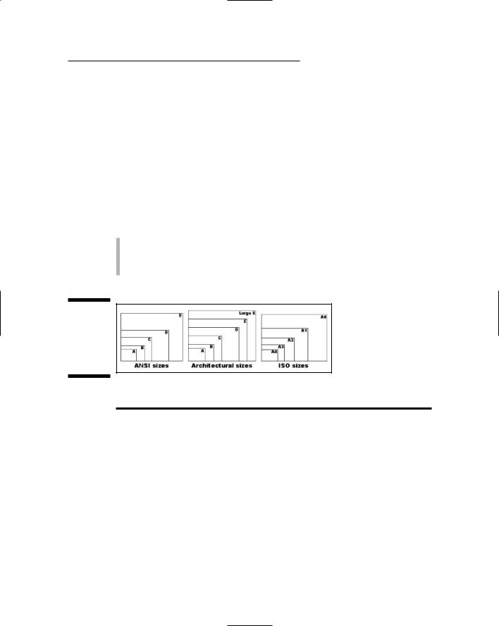
With knowledge of your industry’s common drawing scales, you can choose a provisional scale based on what you’re depicting. But you won’t know for sure whether that scale works until you compare it with the size of the paper that you want to use for plotting your drawing. Here again, most industries use a small range of standard sheet sizes. Three common sets of sizes exist, as shown in Figure 3-2 and Table 3-2:
ANSI (American National Standards Institute)
Architectural
ISO (International Standard Organization)
Figure 3-2:
Relationships among standard paper sizes.
Table 3-2 |
Common Plot Sheet Sizes |
|
Sheet Size |
Dimensions |
Comment |
ANSI E |
34 x 44” |
|
|
|
|
ANSI D |
22 x 34” |
E sheet folded in half |
|
|
|
ANSI C |
17 x 22” |
D sheet folded in half |
|
|
|
ANSI B |
11 x 17” |
C sheet folded in half |
|
|
|
ANSI A |
81⁄2 x 11” |
B sheet folded in half |
Architectural Large E |
36 x 48” |
|
|
|
|
Architectural E |
30 x 42” |
|
|
|
|
Architectural D |
24 x 36” |
|
|
|
|
(continued)

48 Part I: AutoCAD 101
Table 3-2 (continued)
Sheet Size |
Dimensions |
Comment |
Architectural C |
18 x 24” |
|
|
|
|
Architectural B |
12 x 18” |
|
|
|
|
Architectural A |
9 x 12” |
|
|
|
|
ISO A0 |
841 x 1189 mm |
|
|
|
|
ISO A1 |
594 x 841 mm |
A0 sheet folded in half |
|
|
|
ISO A2 |
420 x 594 mm |
A1 sheet folded in half |
|
|
|
ISO A3 |
297 x 420 mm |
A2 sheet folded in half |
|
|
|
ISO A4 |
210 x 297 mm |
A3 sheet folded in half |
|
|
|
You select a particular set of sheet sizes based on the common practices in your industry. You then narrow down your choice based on the area required by what you’re going to draw. For example, most architectural plans are plotted on Architectural D or E size sheets.
If you know the desired sheet size and drawing scale factor, you can calculate the available drawing area easily. Simply multiply each of the sheet’s dimensions (X and Y) by the drawing scale factor. For example, if you choose an 11-x-17-inch sheet and a drawing scale factor of 96 (corresponding to a plot scale of 1⁄8” = 1’–0”), you multiply 17 times 96 and 11 times 96 to get an available drawing area of 1,632 inches x 1,056 inches (or 136 feet x 88 feet). If your sheet size is in inches but your drawing scale is in millimeters, you need to multiply by an additional 25.4 to convert from inches to millimeters. For example, with an 11-x-17-inch sheet and a scale of 1:200 (drawing scale factor = 200), you multiply 17 times 200 times 25.4 and 11 times 200 times 25.4 to get 86,360 x 55,880 mm or 86.36 x 55.88 m — not quite big enough for a football field (United States or European football).
Conversely, if you know the sheet size that you’re going to use and the realworld size of what you’re going to draw, and you want to find out the largest plot scale you can use, you have to divide, not multiply. Divide the needed real-world drawing area dimensions (X and Y) by the sheet’s dimensions (X and Y). Take the larger number — either X or Y — and round up to the nearest real drawing scale factor (that is, one that’s commonly used in your industry). For example, suppose you want to draw a 60-x-40-foot or, 720-x-480-inch, floor plan and print it on 11-x-17-inch paper. You divide 720 by 17 and 480 by 11 to get 42.35 and 43.64, respectively. The larger number, 43.64, corresponds in this example to the short dimension of the house and the paper. The nearest larger common architectural drawing scale factor is 48 (corresponding to 1⁄4” = 1’–0”), which leaves a little room for the plotting margin and title block.

Chapter 3: Setup for Success |
49 |
The Cheat Sheet at the front of this book includes two tables that list the available drawing areas for a range of sheet sizes and drawing scales. Use those tables to help you decide on an appropriate paper size and drawing scale, and revert to the calculation method for situations that the tables don’t cover. (If you don’t keep a favorite old calculator on your physical desktop, this may be a good time to put a shortcut to the Windows Calculator on your virtual one.)
When you select a sheet size and drawing scale, always leave some extra room for the following two reasons:
Most plotters and printers can’t print all the way to the edge of the sheet — they require a small margin. For example, my trusty old HewlettPackard LaserJet III has a printable area of about 7.9 x 10.5 inches on an 8.5-x-11-inch ANSI A size (letter size) sheet. (You’ll find this information in the Plot dialog box, as described in Chapter 12.) If you’re a stickler for precision, you can use the printable area instead of the physical sheet area in the calculations described earlier in this section.
Most drawings require some annotations — text, grid bubbles, and so on — outside the objects you’re drawing, plus a title block surrounding the objects and annotations. If you don’t leave some room for the annotations and title block, you’ll end up having to cram things together too much or to change to a different sheet size. Either way, you’ll be slowed
down later in the project when you can least afford it. Figure 3-3 shows an extreme example of selecting a sheet size that’s too small or, conversely, a drawing scale that’s too large. In this example, the building is too long for the sheet, and it overlaps the title block on both the right and left sides.
Some industries deal with the “sheet-is-too-small/drawing-scale-is-too-large” problem by breaking drawings up onto multiple plotted sheets.
Don’t be afraid to start with paper. Experienced drafters often make a quick, throwaway pencil and paper sketch called a cartoon. A drawing cartoon usually includes a rectangle indicating the sheet of paper you intend to plot on, a sketch of the title block, and a very rough, schematic sketch of the thing you’re going to draw. It helps to scribble down the dimensions of the sheet, the main title block areas, and the major objects to be drawn. By sketching out a cartoon, you’ll often catch scale or paper size problems before you set up a drawing, when repairs only take a few minutes, not after you’ve created the drawing, when fixing the problem can take hours.