- •1. TABLE OF CONTENTS
- •2. BASIC MANUFACTURING
- •2.1 INTRODUCTION
- •2.2 PRACTICE PROBLEMS
- •3. MANUFACTURING COST ESTIMATING
- •3.1 COSTS ESTIMATES
- •3.2 COGS (COST OF GOODS SOLD)
- •3.3 VALUE ENGINEERING
- •3.4 REFERENCES
- •4. BASIC CUTTING TOOLS
- •4.1 CUTTING SPEEDS, FEEDS, TOOLS AND TIMES
- •4.2 HIGH SPEED MACHINING
- •4.3 REFERENCES
- •5. CUTTING THEORY
- •5.1 CHIP FORMATION
- •5.2 THE MECHANISM OF CUTTING
- •5.2.1 Force Calculations
- •5.2.1.1 - Force Calculations
- •5.2.1.2 - Merchant’s Force Circle With Drafting (Optional)
- •5.3 POWER CONSUMED IN CUTTING
- •5.4 PRACTICE QUESTIONS
- •5.5 TEMPERATURES IN CUTTING
- •5.6 TOOL WEAR
- •5.7 CUTTING TOOL MATERIALS
- •5.7.1 A Short List of Tool Materials
- •5.8 TOOL LIFE
- •5.8.1 The Economics of Metal Cutting
- •5.9 REFERENCES
- •5.10 PRACTICE PROBLEMS
- •6. SAWS
- •6.1 SPEEDS AND FEEDS
- •6.2 PRACTICE PROBLEMS
- •7. DRILLING
- •7.1 TYPES OF DRILL PRESSES
- •7.2 TYPICAL DRILL PRESS OPERATIONS
- •7.3 TYPICAL DRILL BITS
- •7.3.1 Reamers
- •7.3.2 Boring
- •7.3.3 Taps
- •7.4 DRILLING PROCESS PARAMETERS
- •7.4.1 The mrr For Drilling
- •7.5 PRACTICE PROBLEMS
- •8. LATHES
- •8.1 INTRODUCTION
- •8.2 OPERATIONS ON A LATHE
- •8.2.1 Machine tools
- •8.2.1.1 - Production Machines
- •8.3 LATHE TOOLBITS
- •8.3.1 Thread Cutting On A Lathe
- •8.3.2 Cutting Tapers
- •8.3.3 Turning Tapers on Lathes
- •8.4 FEEDS AND SPEEDS
- •8.4.1 The mrr for Turning
- •8.4.2 Process Planning for Turning
- •8.5 PRACTICE PROBLEMS
- •9. MILLING
- •9.1 INTRODUCTION
- •9.1.1 Types of Milling Operations
- •9.1.1.1 - Arbor Milling
- •9.1.2 Milling Cutters
- •9.1.3 Milling Cutting Mechanism
- •9.1.3.1 - Up-Cut Milling
- •9.1.3.2 - Down-Cut Milling
- •9.2 FEEDS AND SPEEDS
- •9.2.1 The mrr for Milling
- •9.2.2 Process Planning for Prismatic Parts
- •9.2.3 Indexing
- •9.3 PRACTICE PROBLEMS
- •10. GRINDING
- •10.1 OPERATIONS
- •10.2 MACHINE TYPES
- •10.2.1 Surface
- •10.2.2 Center
- •10.2.3 Centerless
- •10.2.4 Internal
- •10.3 GRINDING WHEELS
- •10.3.1 Operation Parameters
- •10.4 PRACTICE PROBLEMS
- •11. SURFACES
- •11.1 MEASURES OF ROUGHNESS
- •11.2 METHODS OF MEASURING SURFACE ROUGHNESS
- •11.2.1 Observation Methods
- •11.2.2 Stylus Equipment
- •11.2.3 Specifications on Drawings
- •11.3 OTHER SYSTEMS
- •11.4 PRACTICE PROBLEMS
- •11.4.0.1 - Roundness Testing
- •11.4.0.1.1 - Intrinsic Roundness Testing
- •11.4.0.1.2 - Extrinsic Roundness Testing
- •11.4.0.1.3 - Practice Problems
- •11.5 PRACTICE PROBLEMS
- •35. METROLOGY
- •35.1 INTRODUCTION
- •35.1.1 The Role of Metrology
- •35.2 DEFINITIONS
- •35.3 STANDARDS
- •35.3.1 Scales
- •35.3.2 Calipers
- •35.3.3 Transfer Gauges
- •35.4 INSTRUMENTS
- •35.4.1 Vernier Scales
- •35.4.2 Micrometer Scales
- •35.4.2.1 - The Principle of Magnification
- •35.4.2.2 - The Principle of Alignment
- •35.4.3 Dial Indicators
- •35.4.4 The Tool Makers Microscope
- •35.4.5 Metrology Summary
- •35.5 PRACTICE PROBLEMS
- •35.5.0.1 - Interferometry (REWORK)
- •35.5.0.1.1 - Light Waves and Interference
- •35.5.0.1.2 - Optical Flats
- •35.5.0.1.3 - Interpreting Interference Patterns
- •35.5.0.1.4 - Types of Interferometers
- •35.5.0.2 - Laser Measurements of Relative Distance
- •35.5.0.2.1 - Practice Problems
- •35.6 GAUGE BLOCKS
- •35.6.1 Manufacturing Gauge Blocks
- •35.6.2 Compensating for Temperature Variations
- •35.6.2.1 - References
- •35.6.3 Testing For Known Dimensions With Standards
- •35.6.3.1 - References
- •35.6.4 Odd Topics
- •35.6.5 Practice Problems
- •35.6.6 Limit (GO & NO GO) Gauges
- •35.6.6.1 - Basic Concepts
- •35.6.6.2 - GO & NO GO Gauges Using Gauge Blocks
- •35.6.6.3 - Taylor’s Theory for Limit Gauge Design
- •35.6.6.4.1 - Sample Problems
- •35.6.7 Sine Bars
- •35.6.7.1 - Sine Bar Limitations
- •35.6.7.1.1 - Practice Problems
- •35.6.8 Comparators
- •35.6.8.1 - Mechanical Comparators
- •35.6.8.2 - Mechanical and Optical Comparators
- •35.6.8.3 - Optical Comparators
- •35.6.8.4 - Pneumatic Comparators
- •35.6.9 Autocollimators
- •35.6.10 Level Gauges
- •35.6.10.1 - Clinometer
- •35.6.10.2 - The Brookes Level Comparator
- •35.6.11 The Angle Dekkor
- •35.7 MEASURING APARATUS
- •35.7.1 Reference Planes
- •35.7.1.1 - Granite Surface Plates
- •35.7.1.2 - Cast Iron Surface Plates
- •35.7.2 Squares
- •35.7.2.1 - Coordinate Measureing Machines
- •35.7.2.2 - Practice Problems
- •AM:35.7.3 Coordinate Measuring Machines (CMM)
- •36. ASSEMBLY
- •36.1 THE BASICS OF FITS
- •36.1.1 Clearance Fits
- •36.1.2 Transitional Fits
- •36.1.3 Interference Fits
- •36.2 C.S.A. B97-1 1963 LIMITS AND FITS(REWORK)
- •36.3 CSA MODIFIED FITS
- •36.4 CSA LIMITS AND FITS
- •36.5 THE I.S.O. SYSTEM
- •36.6 PRACTICE PROBLEMS
- •42. WELDING/SOLDERING/BRAZING
- •42.1 ADHESIVE BONDING
- •42.2 ARC WELDING
- •42.3 GAS WELDING
- •42.4 SOLDERING AND BRAZING
- •42.5 TITANIUM WELDING
- •42.5.1 Practice Problems
- •42.6 PLASTIC WELDING
- •42.7 EXPLOSIVE WELDING
- •42.7.1 Practice Problems
- •43. AESTHETIC FINISHING
- •43.1 CLEANING AND DEGREASING
- •43.2 PAINTING
- •43.2.1 Powder Coating
- •43.3 COATINGS
- •43.4 MARKING
- •43.4.1 Laser Marking
- •43.5 PRACTICE PROBLEMS
- •44. METALLURGICAL TREATMENTS
- •44.1 HEAT TREATING
- •44.2 ION NITRIDING
- •44.3 PRACTICE PROBLEMS
- •45. CASTING
- •45.1 SAND CASTING
- •45.1.1 Molds
- •45.1.2 Sands
- •45.2 SINGLE USE MOLD TECHNIQUES
- •45.2.1 Shell Mold Casting
- •45.2.2 Lost Foam Casting (Expandable Pattern)
- •45.2.3 Plaster Mold Casting
- •45.2.4 Ceramic Mold Casting
- •45.2.5 Investment Casting
- •45.3 MULTIPLE USE MOLD TECHNIQUES
- •45.3.1 Vacuum Casting
- •45.3.2 Permanent Mold Casting
- •45.3.2.1 - Slush Casting
- •45.3.2.2 - Pressure Casting
- •45.3.2.3 - Die Casting
- •45.3.3 Centrifugal Casting
- •45.3.4 Casting/Forming Combinations
- •45.3.4.1 - Squeeze Casting
- •45.3.4.2 - Semisolid Metal Forming
- •45.3.5 Single Crystal Casting
- •45.4 OTHER TOPICS
- •45.4.1 Furnaces
- •45.4.2 Inspection of Casting
- •45.5 Design of Castings
- •45.6 REFERENECES
- •45.7 PRACTICE PROBLEMS
- •46. MOLDING
- •46.1 REACTION INJECTION MOLDING (RIM)
- •46.1.1 References
- •46.2 INJECTION MOLDING
- •46.2.1 Hydraulic Pumps/Systems
- •46.2.2 Molds
- •46.2.3 Materials
- •46.2.4 Glossary
- •46.3 EXTRUSION
- •46.4 PRACTICE PROBLEMS
- •47. ROLLING AND BENDING
- •47.1 BASIC THEORY
- •47.2 SHEET ROLLING
- •47.3 SHAPE ROLLING
- •47.4 BENDING
- •48. SHEET METAL FABRICATION
- •48.1 SHEET METAL PROPERTIES
- •48.2 SHEARING
- •48.2.1 Progressive and Transfer Dies
- •48.2.2 DRAWING
- •48.3 DEEP DRAWING
- •48.4 SPINNING
- •48.5 MAGNETIC PULSE FORMING
- •48.6 HYDROFORMING
- •48.7 SUPERPLASTIC FORMING
- •48.7.1 Diffusion Bonding
- •48.8 PRACTICE PROBLEMS
- •49. FORGING (to be expanded)
- •49.1 PROCESSES
- •49.1.1 Open-Die
- •49.1.2 Impression/Closed Die
- •49.1.3 Heading
- •49.1.4 Rotary Swaging
- •50. EXTRUSION AND DRAWING
- •50.1 DIE EXTRUSION
- •50.1.1 Hot Extrusion
- •50.1.2 Cold Extrusion
- •50.2 HYDROSTATIC EXTRUSION
- •50.3 DRAWING
- •50.4 EQUIPMENT
- •50.5 PRACTICE PROBLEMS
- •51. ELECTROFORMING
- •51.1 PRACTICE PROBLEMS
- •52. COMPOSITE MANUFACTURING
- •52.1 FIBER REINFORCED PLASTICS (FRP)
- •52.2 COMPOSITE MANUFACTURING
- •52.2.1 Manual Layup
- •52.2.2 Automated Tape Lamination
- •52.2.3 Cutting of Composites
- •52.2.4 Vacuum Bags
- •52.2.5 Autoclaves
- •52.2.6 Filament Winding
- •52.2.7 Pultrusion
- •52.2.8 Resin-Transfer Molding (RTM)
- •52.2.9 GENERAL INFORMATION
- •52.2.10 REFERENCES
- •52.2.11 PRACTICE PROBLEMS
- •53. POWDERED METALLURGY
- •53.1 PRACTICE PROBLEMS
- •54. ABRASIVE JET MACHINING (AJM)
- •54.1 REFERENCES
- •54.2 PRACTICE PROBLEMS
- •55. HIGH PRESSURE JET CUTTING
- •56. ABRASIVE WATERJET CUTTING (AWJ)
- •57. ULTRA SONIC MACHINING (USM)
- •57.1 REFERENCES
- •57.1.1 General Questions
- •58. ELECTRIC DISCHARGE MACHINING (EDM)
- •58.1 WIRE EDM
- •58.2 PRACTICE PROBLEMS
- •58.3 REFERENCES
- •59. ELECTROCHEMICAL MACHINING (ECM)
- •59.1 REFERENCES
- •59.2 PRACTICE PROBLEMS
- •60. ELECTRON BEAM MACHINING
- •60.1 REFERENCES
- •60.2 PRACTICE PROBLEMS
- •61. ION IMPLANTATION
- •61.1 THIN LAYER DEPOSITION
- •61.2 PRACTICE PROBLEMS
- •62. ELECTROSTATIC SPRAYING
- •62.1 ELECTROSTATIC ATOMIZATION METHOD
- •62.2 PRACTICE PROBLEMS
- •63. AIR-PLASMA CUTTING
- •63.1 REFERENCES
- •63.2 PRACTICE PROBLEMS
- •64. LASER CUTTING
- •64.1 LASERS
- •64.1.1 References
- •64.2 LASER CUTTING
- •64.2.1 References
- •64.3 PRACTICE PROBLEMS
- •65. RAPID PROTOTYPING
- •65.1 STL FILE FORMAT
- •65.2 STEREOLITHOGRAPHY
- •65.2.1 Supports
- •65.2.2 Processing
- •65.2.3 References
- •65.3 BONDED POWDERS
- •65.4 SELECTIVE LASER SINTERING (SLS)
- •65.5 SOLID GROUND CURING (SGC)
- •65.6 FUSED DEPOSITION MODELLING (FDM)
- •65.7 LAMINATE OBJECT MODELING (LOM)
- •65.8 DIRECT SHELL PRODUCTION CASTING (DSPC)
- •65.9 BALLISTIC PARTICLE MANUFACTURING (BPM)
- •65.9.1 Sanders Prototype
- •65.9.2 Design Controlled Automated Fabrication (DESCAF)
- •65.10 COMPARISONS
- •65.10.1 References
- •65.11 AKNOWLEDGEMENTS
- •65.12 REFERENCES
- •65.13 PRACTICE PROBLEMS
- •66. PROCESS PLANNING
- •66.1 TECHNOLOGY DRIVEN FEATURES
- •66.2 MOST SIGNIFICANT FEATURE FIRST
- •66.3 DATABASE METHODS
- •66.4 MANUFACTURING VOLUMES
- •66.5 STANDARD PARTS
- •66.6 PRACTICE PROBLEMS
- •66.6.1 Case Study Problems
- •66.6.1.1 - Case 1
- •66.7 REFERENCES
page 375
58.2 PRACTICE PROBLEMS
1.We try an EDM process where the copper tool has a mass of 200g before beginning and 180g after. The iron workpiece drops from 3.125kg to 3.096kg, but has rounded corners.
a)What is the tool wear factor?
b)If the tool was cylindrical to begin with, draw sketches of the electrode before and after.
2.What are the selection criteria for choosing between machining and EDM?
ans. EDM is particularly useful when dealing with internal cuts that are hard to get tools into. Machining tends to work best with external cuts. EDM is suitable for removal of smaller amounts of material at a much slower rate.
58.3 REFERENCES
Ghosh, A., Manufacturing Science, Ellis Horwood Ltd., Chichester, UK, 1986.
Lascoe, O.D., Handbook of Fabrication Processes, American Society of Materials, Metals Park, Ohio, 1988.
59. ELECTROCHEMICAL MACHINING (ECM)
•The physics - an electrode and workpiece (conductor) are placed in an electrolyte, and a potential voltage is applied. On the anode (+ve) side the metal molecules ionize (lose electrons) break free of the workpiece, and travel through the electrolyte to the electrode (a cathode; has a -ve charge; a surplus of electrons).
•NOTE: in EDM an arc was used to heat metal, here the metal dissolves chemically.
page 376
cathode electrode
electrolyte
current density (closer sections have higher density)
anode work
electrode is moved down to cut
•Variation in the current density will result in work taking the electrodes shape.
•The electrode is fed with a constant velocity, and the electrolyte is fed through the tool. The tool is designed to eliminate deposition of the ionized metal on the electrode.
electrolyte is pumped
using high pressure
insulation
Vs
electrolyte splashes out
•Supply V = 8 to 20V, I = >1000A.
•Electrode gap is typically 0.1 to 0.2 mm.
•mrr is about 1600mm3/min. per 1000A, OR 3KWhr for 16000 mm3 (not very efficient, 30 times
page 377
more than standard machining techniques).
•mrr is independent of material hardness.
•Good for low machinability, or complicated shapes.
•Very little tool wear,
•Forces are large with this method because of fluid pumping forces.
•Faraday’s laws state that,
m = |
Itε |
|
------ |
||
|
|
F |
m = |
weight (g) of a material |
|
I |
= |
current (A) |
t |
= |
time (sec) |
ε |
= |
gram equivalent weight of the material |
F= constant of proportionality - Faraday (96,500 coulombs)
•The basic principle is shown below
Cu |
Fe |
|
could be a battery, or electroplating, or ECM bath |
NaCl + H2O electrolyte |
• The chemical reaction between an electrode and the electrolyte leads to electrons being added, or removed from the electrode metal. This addition/subtraction leads to a voltage potential.
page 378
For Iron |
|
|
|
|
Fe |
Fe2 + |
+ 2e– |
V2 |
= –0.409V |
For Copper |
|
|
|
|
Cu |
Cu2 + |
+ 2e– |
V1 |
= 0.304V |
• To make a battery.
|
I |
|
|
Cu |
+ |
- |
Fe |
|
V |
||
|
|
|
|
+ |
- |
+ |
- |
|
V1 |
||
|
V2 |
|
|
|
|
|
V = V1 - V2
V = 0.304V - (-0.409V) = 0.713V
|
|
|
2e– |
|
|
|
2e– |
|
|
2( H2O) |
Fe + |
+ |
||
|
|
|
||
H |
2 |
+ 2( OH) – |
Fe( OH) 2 |
|
|
|
|||
|
|
|
||
|
|
2( OH) – |
= 2e– |
|
• To do electrolysis.
I
Fe |
+ |
- |
Cu |
|
|
V |
|
|
electron |
|
|
|
flow |
|
page 379
In the iron (anode) - the iron dissolves, and 2 electrons are pulled out by the battery.
Fe → Fe++ + 2e–
In the copper (cathode) - extra electrons are pushed in
by the battery and they go to the electrolyte. The electrons liberate hydrogen gas, and create a base.
2e + 2H2O → H2 + 2( OH) –
hydroxides, and the radical iron react to create an insoluble precipitate that falls to the bottom.
Fe++ + 2( OH) – → Fe( OH) 2
The electrodes and electrolyte are chosen so that deposition does not occur at either electrode. (In electrolysis we would want deposition at one of the electrodes.)
• The mrr is,
|
|
|
|
|
|
|
|
|
|
|
|
|
|
|
|
|
AI |
cm |
3 |
|
|
0.1035 10 |
–2 |
|
|
1 |
|
|
cm |
3 |
|
Q = |
|
= |
|
|
|
|
|
||||||||
---------- |
---------- |
------------------------------ρ |
|
|
--------------- |
|
-------------- |
||||||||
|
ρ ZF sec |
|
|
|
|
∑ |
x |
Z |
A sec |
|
|||||
|
|
|
|
|
|
|
|
|
--------i |
i |
|
|
|
|
|
|
|
|
|
|
|
|
|
|
|
Ai |
|
|
|
|
|
|
|
|
|
|
|
|
|
|
|
i |
|
|
|
|
|
for alloys
• e.g.
page 380
Using ECM remove 5cm3/min from an iron workpiece. What current is required?
Q = |
5 |
cm3 |
|
= 5 |
cm3 |
|
1min |
= |
5 cm3 |
||
---------min |
|
---------min |
|
----------------- |
60----- ----------sec |
||||||
|
|
|
|
|
60 sec |
|
|||||
I |
= ? |
|
|
|
|
|
|
|
|
|
|
A = 56g (periodic table) |
|
|
|||||||||
ρ |
|
|
|
g |
|
|
|
|
|
|
|
= 7.8 |
--------- |
(from handbook) |
|
|
|||||||
cm |
3 |
|
|
||||||||
|
|
|
|
|
|
|
|
|
|
|
|
Z = 2 (from chemical reaction) |
|
|
|||||||||
F = 96, 500 coulombs |
|
|
|||||||||
|
5 |
= |
|
|
56I |
|
|
|
|
||
----- |
7.8-------------------------------------- |
( 2) ( 96, 500) |
|
|
|||||||
|
60 |
|
|
|
|
I= 2240A
•Actual rates may vary from theory as other factors come into effect.
Theory |
for nickel |
mrr (g/min) |
Current (A) |
This can be caused by other chemical reactions also taking place. e.g. production of Fe3+ instead of Fe2+ ions can result when a
larger current or different electrolyte is used.
• The table below shows various materials and relevant properties,
page 381
metal |
gram atomic |
valency of |
density |
|
weight |
dissolution |
(g/cm3) |
aluminum |
26.97 |
3 |
2.67 |
chromium |
51.99 |
2/3/6 |
7.19 |
cobalt |
58.93 |
2/3 |
8.85 |
copper |
63.57 |
1/2 |
8.96 |
iron |
55.85 |
2/3 |
7.86 |
nickel |
58.71 |
2/3 |
8.90 |
tin |
118.69 |
2/4 |
7.30 |
titanium |
47.9 |
3/4 |
4.51 |
tungsten |
183.85 |
6/8 |
19.3 |
zinc |
65.37 |
2 |
7.13 |
silicon |
28.09 |
4 |
2.33 |
manganese |
54.94 |
2/4/6/7 |
7.43 |
carbon |
|
2/4 |
1.8-2.1 |
• e.g.
page 382
The composition of the Nimonic 75 alloy is given below. Find the mmr for a current of 1000A.
|
|
|
|
|
|
|
Q = |
0.1035× 10⁻² |
|
|
1 |
|
|
------------------------------ |
|
--------------------- |
||||
|
ρ |
|
∑ |
x Z |
|
|
|
|
|
-------- |
|||
|
|
|
|
i |
i |
|
|
|
|
|
Ai |
||
|
|
|
i |
|
|
|
%component
72.5Ni
19.5Cr
5.0Fe
0.4Ti
1.0Si
1.0Mn
0.6Cu
ρ = |
100 |
|
|
|
|
|
|
|
|
|
|
|
100 |
|
|
|
|
|
|
|
|
|
g |
|
|
|
|
xi |
= |
---------------------------------------------------------------------------------------------------------------- |
= |
8.18 |
--------- |
|
|||||||||||||||||||
|
72.5 |
+ |
19.5 |
+ |
|
5.0 |
+ |
0.4 |
+ |
1 |
+ |
1 |
+ |
0.6 |
cm |
3 |
|
|||||||||
∑ |
---- |
|
--------- |
|
--------- |
--------- |
|
|
--------- |
--------- |
--------- |
--------- |
|
|
|
|
|
|||||||||
|
ρ i |
|
8.9 |
|
7.19 |
|
|
7.86 |
|
4.51 |
|
2.33 |
|
7.43 |
|
8.96 |
|
|
|
|
|
|
||||
|
|
|
|
|
|
|
|
|
|
|
|
|
|
|
||||||||||||
|
i |
|
|
|
|
|
|
|
|
|
|
|
|
|
|
|
|
|
|
|
|
|
|
|
|
|
|
0.1035× 10 |
–2 |
|
|
|
|
|
|
|
|
|
|
|
|
1 |
|
|
|
|
|
|
|
|
|||
|
|
|
|
|
|
|
|
|
|
|
|
|
|
|
|
|
|
|
|
|
|
|||||
Q = |
|
8.18------------------------------ |
|
---------------------------------------------------------------------------------------------------------------------------------------------------- |
||||||||||||||||||||||
|
|
|
|
( 72.5) 2 |
|
|
( 19.5) 2 |
( 5) 2 |
|
( 0.4) 3 |
( 1) 4 |
|
( 1) 2 |
|
( 0.6) 1 |
|||||||||||
|
|
|
|
|
|
------------------ |
58.71 |
|
+ |
------------------51.99 + 55.85------------ |
+ |
---------------47.9 |
+ 28.09------------ |
+ |
54.94------------ + |
--------------63.57 |
||||||||||
Q = |
0.35× 10 |
–4 cm3 |
|
|
|
|
|
|
|
|
|
|
|
|
|
|
|
|
|
|
|
|
||||
-------------- |
|
|
|
|
|
|
|
|
|
|
|
|
|
|
|
|
|
|
|
|||||||
|
|
|
|
A sec |
|
|
|
|
|
|
|
|
|
|
|
|
|
|
|
|
|
|
|
|
||
therefore, for 1 min, and 1000A |
|
|
|
|
|
|
|
|
|
|
|
|
|
|
||||||||||||
|
|
|
|
= 0.35× 10 |
–4 |
( 1000) ( 60) |
|
|
cm3 |
|
|
|
|
|
|
|
|
|||||||||
|
|
|
|
|
|
|
|
--------- |
|
|
|
|
|
|
|
|
||||||||||
|
|
|
|
|
|
|
= 2.1 min |
|
|
|
|
|
|
|
|
•While the current required is related to the metal removed, the voltage required depends upon,
-electrode potential.
-the current flow in and about the electrodes will disturb the normal distribution of voltage. Extra potential is required to overcome the effects.
-Ion collect near electrodes and impede ion transfer from the electrode to the electrolyte, also adding a potential.
-Some solid film forms on the surface of the electrode, also increasing resistance.
-electrolyte resistance,
I |
= |
V – ∆ V |
|
---------------- |
|||
1 |
|
R |
|
= |
10 → 1( Ω cm) |
||
-- |
|||
R |
|
|
page 383
required V |
|
|
|
anode potential |
|
|
activation polarization overvoltage |
|
|
ohmic overvoltage |
|
|
concentration polarization overvoltage |
|
|
electrolyte ohmic voltage |
cathode |
|
|
|
anode |
concentration polarization overvoltage |
|
|
||
|
|
ohmic overvoltage |
|
activation polarization overvoltage |
|
|
|
cathode potential |
|
|
distance |
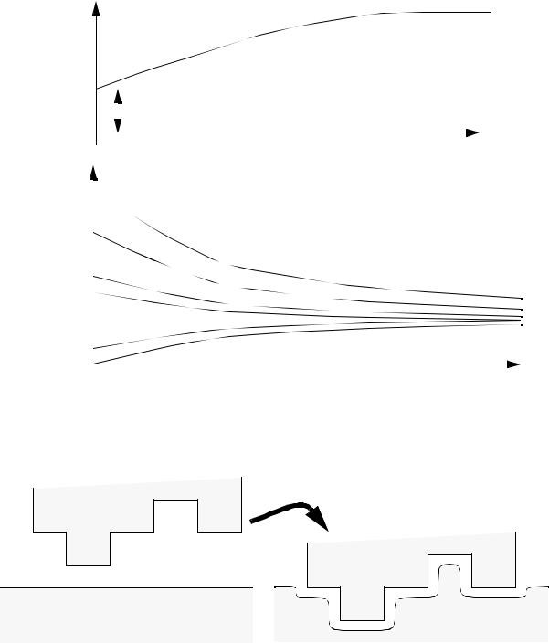
• The feed of the electrodes has the following effects
+ |
- |
|
tool |
|
v |
|
y |
|
work |
dy |
= |
|
KA( V – ∆ V) |
|
1 |
– v |
|
|
|||||
----- |
|
-----------------------------ρ ZF |
|
-- |
||
dt |
|
|
|
y |
|
K = conductivity of electrolyte( Ω –1)
page 384
y(t)
|
|
|
|
|
|
|
|
|
|
|
|
|
|
|
|
|
|
|
|
|
|
|
|
|
|
|
|
for electrode velocity v = 0 |
|
|
|
|
|
|
|
|
|
||||||||||||||||||||||||
|
|
|
|
|
|
|
|
y0 |
|
|
t |
||||||||||||||||||||||||||||||||||||||||||||||||||
|
|
|
|
|
|
|
|
|
|
|
|
|
|
|
|
|
|
|
|
|
|
|
|
|
|
|
|
|
|
|
|
|
|
|
|
|
|
|
|
|
|
|
|||||||||||||||||||
|
|
|
|
|
|
|
|
|
|
|
|
|
|
|
|
|
|
|
|
|
|
|
|
|
|
|
|
|
|
|
|
|
|
|
|
|
|
|
|
|
|
|
|||||||||||||||||||
|
|
|
|
|
|
|
|
|
|
|
|
|
|
|
|
|
|
|
|
|
|
|
|
|
|
|
|
|
|
|
|
|
|
|
|
|
|
|
|
|
|
|
|
|
|
|
|
|
|
|
|
|
|
|
|||||||
4 |
|
|
|
|
gap |
|
|
|
|
|
|
|
|
|
|
|
|
|
|
|
|
|
|
|
|
|
|
|
|
|
|
|
|
|
|
|
|
|
|||||||||||||||||||||||
|
|
|
|
|
|
|
|
|
|
|
|
|
|
|
|
|
|
|
|
|
|
|
|
|
|
|
|
|
|
|
|
|
|
|
|
|
|
|
|
|
|
|
|
|
|
||||||||||||||||
|
|
|
|
|
|
|
|
|
y0 = 4 |
|
|
For electrode starting above/below equilibrium |
|||||||||||||||||||||||||||||||||||||||||||||||||
|
|
|
|
|
|
|
|
|
|
|
|
||||||||||||||||||||||||||||||||||||||||||||||||||
|
|
|
|
|
|
|
|
|
|
|
|
electrode gap - eventually the electrode approaches |
|||||||||||||||||||||||||||||||||||||||||||||||||
3 |
|
|
|
|
3 |
|
|
|
|
|
|
|
|
|
|
|
|
the equilibrium gap. |
|
|
|
|
|
|
|
|
|
|
|
|
|
|
|
|
|
|
|
|
|
|
|
|
|||||||||||||||||||
2 |
|
|
|
|
|
|
|
|
|
|
|
|
|
|
|
|
|
|
|
|
|
|
|
|
|
|
|
|
|
|
|
|
|
|
|
|
|
|
|
|
|
|
|
|
|
|
|
|
|
|
|
|
|
|
|
||||||
|
|
|
|
2 |
|
|
|
|
|
|
|
|
|
|
|
|
|
|
|
|
|
|
|
|
|
|
|
|
|
|
|
|
|
|
|
|
|
|
|
|
|
|
|
|
|
|
|
|
|
|
|
|
|
|
|
|
|||||
|
|
|
|
|
|
|
|
|
|
|
|
|
|
|
|
|
|
|
y |
|
|
|
|
|
|
|
|
|
|
|
|
|
|
|
|
|
|
|
|
|
|
|
|
||||||||||||||||||
|
|
|
1.5 |
|
|
|
|
|
|
|
|
|
|
|
|
|
|
|
|
|
|
|
|
|
|
|
|
|
|
|
|
|
|
|
|
|
|
|
|
|
|
|
|||||||||||||||||||
1 |
|
|
|
|
|
|
|
|
|
|
|
|
|
|
|
|
|
|
|
|
|
|
|
|
|
|
|
|
|
|
|
|
|
|
|
|
|
|
|
|
|
|
|
|
|
|
|
|
|
|
|
|
|
|
|||||||
|
|
|
|
|
|
|
|
|
|
|
|
|
|
|
|
|
|
|
|
|
|
|
|
|
|
|
|
|
|
|
|
|
|
|
|
|
|
|
|
|
|
|
|
|
|
|
|
|
|
|
|
|
|
|
|
|
|
|
|
|
|
|
|
|
0.5 |
|
|
|
|
|
|
|
|
|
|
|
|
|
|
|
|
|
|
|
|
|
|
|
|
|
|
|
|
|
|
|
|
|
|
|
|
|
|
|
|
|
|
|
|
|
|
|
|
|
|
|
|||||||
0 |
|
|
0 |
|
|
|
|
|
|
|
|
|
|
|
|
|
|
|
|
|
|
|
|
|
|
|
|
|
|
|
|
|
|
|
|
|
|
|
|
|
|
|
|
|
|
|
|
|
|
|
|
||||||||||
|
|
|
|
|
|
|
|
|
|
|
|
|
|
|
|
|
|
|
|
|
|
|
|
|
|
|
|
|
|
|
|
|
|
|
|
|
|
|
|
|
|
|
|
|
|
|
|
|
|
||||||||||||
|
|
|
2 |
|
4 |
|
|
|
|
|
6 |
|
|
|
|
|
|
t |
|||||||||||||||||||||||||||||||||||||||||||
|
|
|
|
|
|
|
|
|
|
|
|
|
|
• The ECM process will erode material in a radial direction, so care must be made in tooling design.
Produces
•As current flows through the electrolyte, it is heated, and conductivity decreases.
•Surface finish is affected by,
-selective dissolution
-sporadic breakdown of the anodic film