

Furber S.ARM system-on-chip architecture.2000
.pdfThe ARM programmer's model |
39 |
2.3The ARM programmer's model
A processor's instruction set defines the operations that the programmer can use to change the state of the system incorporating the processor. This state usually comprises the values of the data items in the processor's visible registers and the system's memory. Each instruction can be viewed as performing a defined transformation from the state before the instruction is executed to the state after it has completed. Note that although a processor will typically have many invisible registers involved in executing an instruction, the values of these registers before and after the instruction is executed are not significant; only the values in the visible registers have any significance. The visible registers in an ARM processor are shown in Figure 2.1.
When writing user-level programs, only the 15 general-purpose 32-bit registers (r0 to r!4), the program counter (r15) and the current program status register (CPSR) need be considered. The remaining registers are used only for system-level programming and for handling exceptions (for example, interrupts).
Figure 2.1 ARM's visible registers.
40 |
The ARM Architecture |
The Current
Program Status
Register (CPSR)
The memory system
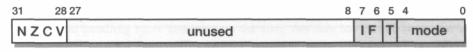
Figure 2.2 ARM CPSR format.
The CPSR is used in user-level programs to store the condition code bits. These bits are used, for example, to record the result of a comparison operation and to control whether or not a conditional branch is taken. The user-level programmer need not usually be concerned with how this register is configured, but for completeness the register is illustrated in Figure 2.2. The bits at the bottom of the register control the processor mode (see Section 5.1 on page 106), instruction set ('T', see Section 7.1 on page 189) and interrupt enables ('I' and 'F', see Section 5.2 on page 108) and are protected from change by the user-level program. The condition code flags are in the top four bits of the register and have the following meanings:
•N: Negative; the last ALU operation which changed the flags produced a negative result (the top bit of the 32-bit result was a one).
•Z: Zero; the last ALU operation which changed the flags produced a zero result (every bit of the 32-bit result was zero).
•C: Carry; the last ALU operation which changed the flags generated a carry-out, either as a result of an arithmetic operation in the ALU or from the shifter.
•V: oVerflow; the last arithmetic ALU operation which changed the flags generated an overflow into the sign bit.
Note that although the above definitions for C and V look quite complex, their use does not require a detailed understanding of their operation. In most cases there is a simple condition test which gives the desired result without the programmer having to work out the precise values of the condition code bits.
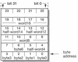
In addition to the processor register state, an ARM system has memory state. Memory may be viewed as a linear array of bytes numbered from zero up to 232-l. Data items may be 8-bit bytes, 16-bit half-words or 32-bit words. Words are always aligned on 4-byte boundaries (that is, the two least significant address bits are zero) and half-words are aligned on even byte boundaries.
The memory organization is illustrated in Figure 2.3 on page 41. This shows a small area of memory where each byte location has a unique number. A byte may occupy any of these locations, and a few examples are shown in the figure. A word-sized data item must occupy a group of four byte locations starting at a byte address which is a multiple of four, and again the figure contains a couple of examples. Half-words occupy two byte locations starting at an even byte address.
The ARM programmer's model |
41 |
|
Figure 2.3 ARM memory organization. |
|
(This is the standard, 'little-endian', memory organization used by the ARM. ARM |
|
can also be configured to work with a 'big-endian' memory organization; we will |
|
return to this issue in Chapter 5.) |
Load-store |
In common with most RISC processors, ARM employs a load-store architecture. |
architecture |
This means that the instruction set will only process (add, subtract, and so on) |
|
values which are in registers (or specified directly within the instruction itself), and |
|
will always place the results of such processing into a register. The only operations |
|
which apply to memory state are ones which copy memory values into registers |
|
(load instructions) or copy register values into memory (store instructions). |
|
CISC processors typically allow a value from memory to be added to a value in a |
|
register, and sometimes allow a value in a register to be added to a value in memory. |
|
ARM does not support such 'memory-to-memory' operations. Therefore all ARM |
|
instructions fall into one of the following three categories: |
|
1. Data processing instructions. These use and change only register values. For |
|
example, an instruction can add two registers and place the result in a register. |
|
2. Data transfer instructions. These copy memory values into registers (load |
|
instructions) or copy register values into memory (store instructions). An addi |
|
tional form, useful only in systems code, exchanges a memory value with a reg |
|
ister value. |
|
3. Control flow instructions. Normal instruction execution uses instructions stored |
|
at consecutive memory addresses. Control flow instructions cause execution to |
|
switch to a different address, either permanently (branch instructions) or saving |
|
a return address to resume the original sequence (branch and link instructions) |
|
or trapping into system code (supervisor calls). |
42 |
The ARM Architecture |
Supervisor mode The ARM processor supports a protected supervisor mode. The protection mechanism ensures that user code cannot gain supervisor privileges without appropriate checks being carried out to ensure that the code is not attempting illegal operations. The upshot of this for the user-level programmer is that system-level functions can only be accessed through specified supervisor calls. These functions generally include any accesses to hardware peripheral registers, and to widely used operations such as character input and output. User-level programmers are principally concerned with devising algorithms to operate on the data 'owned' by their programs, and rely on the operating system to handle all transactions with the world outside their programs. The instructions which request operating system functions are covered in 'Supervisor calls' on page 67.
The ARM instruction set
The I/O system
All ARM instructions are 32 bits wide (except the compressed 16-bit Thumb instructions which are described in Chapter 7) and are aligned on 4-byte boundaries in memory. Basic use of the instruction set is described in Chapter 3 and full details, including the binary instruction formats, are given in Chapter 5. The most notable features of the ARM instruction set are:
•The load-store architecture;
•3-address data processing instructions (that is, the two source operand registers and the result register are all independently specified);
•conditional execution of every instruction;
•the inclusion of very powerful load and store multiple register instructions;
•the ability to perform a general shift operation and a general ALU operation in a single instruction that executes in a single clock cycle;
•open instruction set extension through the coprocessor instruction set, including adding new registers and data types to the programmer's model;
•a very dense 16-bit compressed representation of the instruction set in the Thumb architecture.
To those readers familiar with modern RISC instruction sets, the ARM instruction set may appear to have rather more formats than other commercial RISC processors. While this is certainly the case and it does lead to more complex instruction decoding, it also leads to higher code density. For the small embedded systems that most ARM processors are used in, this code density advantage outweighs the small performance penalty incurred by the decode complexity. Thumb code extends this advantage to give ARM better code density than most CISC processors.
The ARM handles I/O (input/output) peripherals (such as disk controllers, network interfaces, and so on) as memory-mapped devices with interrupt support. The internal registers in these devices appear as addressable locations within the ARM's
ARM development tools |
43 |
memory map and may be read and written using the same (load-store) instructions as any other memory locations.
Peripherals may attract the processor's attention by making an interrupt request using either the normal interrupt (IRQ) or the fast interrupt (FIQ) input. Both interrupt inputs are level-sensitive and maskable. Normally most interrupt sources share the IRQ input, with just one or two time-critical sources connected to the
|
higher-priority FIQ input. |
|
Some systems may include direct memory access (DMA) hardware external to the |
|
processor to handle high-bandwidth I/O traffic. This is discussed further in |
|
Section 11.9 on page 312. |
|
Interrupts are a form of exception and are handled as outlined below. |
ARM exceptions |
The ARM architecture supports a range of interrupts, traps and supervisor calls, all |
|
grouped under the general heading of exceptions. The general way these are handled |
|
is the same in all cases: |
|
1. The current state is saved by copying the PC into rl4_exc and the CPSR into |
|
SPSR_exc (where exc stands for the exception type). |
|
2. The processor operating mode is changed to the appropriate exception mode. |
|
3. The PC is forced to a value between 0016 and 1C16, the particular value depending |
|
on the type of exception. |
|
The instruction at the location the PC is forced to (the vector address) will usually |
|
contain a branch to the exception handler. The exception handler will use rl3_exc, |
|
which will normally have been initialized to point to a dedicated stack in memory, to |
|
save some user registers for use as work registers. |
|
The return to the user program is achieved by restoring the user registers and then |
|
using an instruction to restore the PC and the CPSR atomically. This may involve |
|
some adjustment of the PC value saved in rl4_exc to compensate for the state of the |
|
pipeline when the exception arose. This is described in more detail in Section 5.2 on |
|
page 108. |
2.4ARM development tools
Software development for the ARM is supported by a coherent range of tools developed by ARM Limited, and there are also many third party and public domain tools available, such as an ARM back-end for the gcc C compiler.
Since the ARM is widely used as an embedded controller where the target hardware will not make a good environment for software development, the tools are intended for cross-development (that is, they run on a different architecture from the

44
The ARM C compiler
The ARM Architecture
one for which they produce code) from a platform such as a PC running Windows or a suitable UNIX workstation. The overall structure of the ARM cross-development toolkit is shown in Figure 2.4. C or assembler source files are compiled or assembled into ARM object format (.aof) files, which are then linked into ARM image format (.aif) files. The image format files can be built to include the debug tables required by the ARM symbolic debugger (ARMsd which can load, run and debug programs either on hardware such as the ARM Development Board or using a software emulation of the ARM (the ARMulator). The ARMulator has been designed to allow easy extension of the software model to include system features such as caches, particular memory timing characteristics, and so on.
The ARM C compiler is compliant with the ANSI (American National Standards Institute) standard for C and is supported by the appropriate library of standard functions. It uses the ARM Procedure Call Standard (see Section 6.8 on page 175) for all externally available functions. It can be told to produce assembly source output instead of ARM object format, so the code can be inspected, or even hand optimized, and then assembled subsequently. The compiler can also produce Thumb code.
Figure 2.4 The structure of the ARM cross-development toolkit.
ARM development tools |
45 |
The ARM assembler
The linker
ARMsd
ARMulator
The ARM assembler is a full macro assembler which produces ARM object format output that can be linked with output from the C compiler.
Assembly source language is near machine-level, with most assembly instructions translating into single ARM (or Thumb) instructions. ARM assembly language programming is introduced in the next chapter, and the full details of the ARM instruction set, including assembly language formats, are given in Chapter 5. The Thumb instruction set and assembly language formats are given in Chapter 7.
The linker takes one or more object files and combines them into an executable program. It resolves symbolic references between the object files and extracts object modules from libraries as needed by the program. It can assemble the various components of the program in a number of different ways, depending on whether the code is to run in RAM (Random Access Memory, which can be read and written) or ROM (Read Only Memory), whether overlays are required, and so on.
Normally the linker includes debug tables in the output file. If the object files were compiled with full debug information, this will include full symbolic debug tables (so the program can be debugged using the variable names in the source program). The linker can also produce object library modules that are not executable but are ready for efficient linking with object files in the future.
The ARM symbolic debugger is a front-end interface to assist in debugging programs running either under emulation (on the ARMulator) or remotely on a target system such as the ARM development board. The remote system must support the appropriate remote debug protocols either via a serial line or through a JTAG test interface (see Section 8.6 on page 226). Debugging a system where the processor core is embedded within an application-specific system chip is a complex issue that we will return to in Chapter 8.
At its most basic, ARMsd allows an executable program to be loaded into the ARMulator or a development board and run. It allows the setting of breakpoints, which are addresses in the code that, if executed, cause execution to halt so that the processor state can be examined. In the ARMulator, or when running on hardware with appropriate support, it also allows the setting of watchpoints. These are memory addresses that, if accessed as data addresses, cause execution to halt in a similar way.
At a more sophisticated level ARMsd supports full source level debugging, allowing the C programmer to debug a program using the source file to specify breakpoints and using variable names from the original program.
The ARMulator (ARM emulator) is a suite of programs that models the behaviour of various ARM processor cores in software on a host system. It can operate at various levels of accuracy:
46 |
The ARM Architecture |
•Instruction-accurate modelling gives the exact behaviour of the system state without regard to the precise timing characteristics of the processor.
•Cycle-accurate modelling gives the exact behaviour of the processor on a cycle- by-cycle basis, allowing the exact number of clock cycles that a program requires to be established.
•Timing-accurate modelling presents signals at the correct time within a cycle, allowing logic delays to be accounted for.
All these approaches run considerably slower than the real hardware, but the first incurs the smallest speed penalty and is best suited to software development.
At its simplest, the ARMulator allows an ARM program developed using the C compiler or assembler to be tested and debugged on a host machine with no ARM processor connected. It allows the number of clock cycles the program takes to execute to be measured exactly, so the performance of the target system can be evaluated.
At its most complex, the ARMulator can be used as the centre of a complete, timing-accurate, C model of the target system, with full details of the cache and memory management functions added, running an operating system.
In between these two extremes the ARMulator comes with a set of model prototyping modules including a rapid prototype memory model and coprocessor interfacing support. (There is more detail on this in Section 8.5 on page 225.)
The ARMulator can also be used as the core of a timing-accurate ARM behavioural model in a hardware simulation environment based around a language such as VHDL. (VHDL is a standard, widely supported hardware description language.) A VHDL 'wrapper' must be generated to interface the ARMulator C code to the VHDL environment.
ARM |
The ARM Development Board is a circuit board incorporating a range of compo- |
development |
nents and interfaces to support the development of ARM-based systems. It includes |
board |
an ARM core (for example, an ARM7TDMI), memory components which can be |
|
configured to match the performance and bus-width of the memory in the target sys- |
|
tem, and electrically programmable devices which can be configured to emulate |
|
application-specific peripherals. It can support both hardware and software develop- |
|
ment before the final application-specific hardware is available. |
Software Toolkit |
ARM Limited supplies the complete set of tools described above, with some support |
|
utility programs and documentation, as the 'ARM Software Development Toolkit'. |
|
The Toolkit CD-ROM includes a PC version of the toolset that runs under most ver- |
|
sions of the Windows operating system and includes a full Windows-based project |
|
manager. The toolkit is updated as new versions of the ARM become available. |
|
The ARM Project Manager is a graphical front-end for the tools described above. It |
|
supports the building of a single library or executable image from a list of files that |
|
make up a particular project. These files may be: |
exercises |
47 |
•source files (C, assembler, and so on);
•object files;
•library files.
The source files may be edited within the Project Manager, a dependency list created and the output library or executable image built. There are many options which may be chosen for the build, such as:
•Whether the output should be optimized for code size or execution time.
•Whether the output should be in debug or release form.
(Code compiled for source-level debugging cannot be fully optimized since the mapping from the source to fully optimized output is too obscure for debugging purposes.)
•Which ARM processor is the target (and, particularly, whether it supports the Thumb instruction set).
The CD-ROM also contains versions of the tools that run on a Sun or HP UNIX host, where a command-line interface is used. All versions have on-line help available.
JumpStart |
The JumpStart tools from VLSI Technology, Inc., include the same basic set of |
|
development tools but present a full X-windows interface on a suitable workstation |
|
rather than the command-line interface of the standard ARM toolkit. There are many |
|
other suppliers of tools that support ARM development. |
2.5Example and exercises
Example 2.1 |
Describe the principal features of the ARM architecture. |
|
The main features of the ARM architecture are: |
|
• a large set of registers, all of which can be used for most purposes; |
|
• a load-store architecture; |
|
• 3-address instructions (that is, the two source operand registers and the result reg |
|
ister are all independently specified); |
|
• conditional execution of every instruction; |
|
• the inclusion of very powerful load and store multiple register instructions; |
|
• the ability to perform a general shift operation and a general ALU operation in a |
|
single instruction that executes in a single clock cycle; |
|
• open instruction set extension through the coprocessor instruction set, including |
|
adding new registers and data types to the programmer's model. |
48
Exercise 2.1.1
Exercise 2.1.2
Exercise 2.1.3
The ARM Architecture
If the Thumb instruction set is considered part of the ARM architecture, we could also add:
• a very dense 16-bit compressed representation of the instruction set in the Thumb architecture.
Which features does ARM have in common with many other RISC architectures?
Which features of the ARM architecture are not shared by most other RISCs? Which
features of most other RISC architectures are not shared by the ARM?