

- •1.1 TODO LIST
- •2. PROGRAMMABLE LOGIC CONTROLLERS
- •2.1 INTRODUCTION
- •2.1.1 Ladder Logic
- •2.1.2 Programming
- •2.1.3 PLC Connections
- •2.1.4 Ladder Logic Inputs
- •2.1.5 Ladder Logic Outputs
- •2.2 A CASE STUDY
- •2.3 SUMMARY
- •2.4 PRACTICE PROBLEMS
- •2.5 PRACTICE PROBLEM SOLUTIONS
- •2.6 ASSIGNMENT PROBLEMS
- •3. PLC HARDWARE
- •3.1 INTRODUCTION
- •3.2 INPUTS AND OUTPUTS
- •3.2.1 Inputs
- •3.2.2 Output Modules
- •3.3 RELAYS
- •3.4 A CASE STUDY
- •3.5 ELECTRICAL WIRING DIAGRAMS
- •3.5.1 JIC Wiring Symbols
- •3.6 SUMMARY
- •3.7 PRACTICE PROBLEMS
- •3.8 PRACTICE PROBLEM SOLUTIONS
- •3.9 ASSIGNMENT PROBLEMS
- •4. LOGICAL SENSORS
- •4.1 INTRODUCTION
- •4.2 SENSOR WIRING
- •4.2.1 Switches
- •4.2.2 Transistor Transistor Logic (TTL)
- •4.2.3 Sinking/Sourcing
- •4.2.4 Solid State Relays
- •4.3 PRESENCE DETECTION
- •4.3.1 Contact Switches
- •4.3.2 Reed Switches
- •4.3.3 Optical (Photoelectric) Sensors
- •4.3.4 Capacitive Sensors
- •4.3.5 Inductive Sensors
- •4.3.6 Ultrasonic
- •4.3.7 Hall Effect
- •4.3.8 Fluid Flow
- •4.4 SUMMARY
- •4.5 PRACTICE PROBLEMS
- •4.6 PRACTICE PROBLEM SOLUTIONS
- •4.7 ASSIGNMENT PROBLEMS
- •5. LOGICAL ACTUATORS
- •5.1 INTRODUCTION
- •5.2 SOLENOIDS
- •5.3 VALVES
- •5.4 CYLINDERS
- •5.5 HYDRAULICS
- •5.6 PNEUMATICS
- •5.7 MOTORS
- •5.8 COMPUTERS
- •5.9 OTHERS
- •5.10 SUMMARY
- •5.11 PRACTICE PROBLEMS
- •5.12 PRACTICE PROBLEM SOLUTIONS
- •5.13 ASSIGNMENT PROBLEMS
- •6. BOOLEAN LOGIC DESIGN
- •6.1 INTRODUCTION
- •6.2 BOOLEAN ALGEBRA
- •6.3 LOGIC DESIGN
- •6.3.1 Boolean Algebra Techniques
- •6.4 COMMON LOGIC FORMS
- •6.4.1 Complex Gate Forms
- •6.4.2 Multiplexers
- •6.5 SIMPLE DESIGN CASES
- •6.5.1 Basic Logic Functions
- •6.5.2 Car Safety System
- •6.5.3 Motor Forward/Reverse
- •6.5.4 A Burglar Alarm
- •6.6 SUMMARY
- •6.7 PRACTICE PROBLEMS
- •6.8 PRACTICE PROBLEM SOLUTIONS
- •6.9 ASSIGNMENT PROBLEMS
- •7. KARNAUGH MAPS
- •7.1 INTRODUCTION
- •7.2 SUMMARY
- •7.3 PRACTICE PROBLEMS
- •7.4 PRACTICE PROBLEM SOLUTIONS
- •7.5 ASSIGNMENT PROBLEMS
- •8. PLC OPERATION
- •8.1 INTRODUCTION
- •8.2 OPERATION SEQUENCE
- •8.2.1 The Input and Output Scans
- •8.2.2 The Logic Scan
- •8.3 PLC STATUS
- •8.4 MEMORY TYPES
- •8.5 SOFTWARE BASED PLCS
- •8.6 SUMMARY
- •8.7 PRACTICE PROBLEMS
- •8.8 PRACTICE PROBLEM SOLUTIONS
- •8.9 ASSIGNMENT PROBLEMS
- •9. LATCHES, TIMERS, COUNTERS AND MORE
- •9.1 INTRODUCTION
- •9.2 LATCHES
- •9.3 TIMERS
- •9.4 COUNTERS
- •9.5 MASTER CONTROL RELAYS (MCRs)
- •9.6 INTERNAL RELAYS
- •9.7 DESIGN CASES
- •9.7.1 Basic Counters And Timers
- •9.7.2 More Timers And Counters
- •9.7.3 Deadman Switch
- •9.7.4 Conveyor
- •9.7.5 Accept/Reject Sorting
- •9.7.6 Shear Press
- •9.8 SUMMARY
- •9.9 PRACTICE PROBLEMS
- •9.10 PRACTICE PROBLEM SOLUTIONS
- •9.11 ASSIGNMENT PROBLEMS
- •10. STRUCTURED LOGIC DESIGN
- •10.1 INTRODUCTION
- •10.2 PROCESS SEQUENCE BITS
- •10.3 TIMING DIAGRAMS
- •10.4 DESIGN CASES
- •10.5 SUMMARY
- •10.6 PRACTICE PROBLEMS
- •10.7 PRACTICE PROBLEM SOLUTIONS
- •10.8 ASSIGNMENT PROBLEMS
- •11. FLOWCHART BASED DESIGN
- •11.1 INTRODUCTION
- •11.2 BLOCK LOGIC
- •11.3 SEQUENCE BITS
- •11.4 SUMMARY
- •11.5 PRACTICE PROBLEMS
- •11.6 PRACTICE PROBLEM SOLUTIONS
- •11.7 ASSIGNMENT PROBLEMS
- •12. STATE BASED DESIGN
- •12.1 INTRODUCTION
- •12.1.1 State Diagram Example
- •12.1.2 Conversion to Ladder Logic
- •12.1.2.1 - Block Logic Conversion
- •12.1.2.2 - State Equations
- •12.1.2.3 - State-Transition Equations
- •12.2 SUMMARY
- •12.3 PRACTICE PROBLEMS
- •12.4 PRACTICE PROBLEM SOLUTIONS
- •12.5 ASSIGNMENT PROBLEMS
- •13. NUMBERS AND DATA
- •13.1 INTRODUCTION
- •13.2 NUMERICAL VALUES
- •13.2.1 Binary
- •13.2.1.1 - Boolean Operations
- •13.2.1.2 - Binary Mathematics
- •13.2.2 Other Base Number Systems
- •13.2.3 BCD (Binary Coded Decimal)
- •13.3 DATA CHARACTERIZATION
- •13.3.1 ASCII (American Standard Code for Information Interchange)
- •13.3.2 Parity
- •13.3.3 Checksums
- •13.3.4 Gray Code
- •13.4 SUMMARY
- •13.5 PRACTICE PROBLEMS
- •13.6 PRACTICE PROBLEM SOLUTIONS
- •13.7 ASSIGNMENT PROBLEMS
- •14. PLC MEMORY
- •14.1 INTRODUCTION
- •14.2 MEMORY ADDRESSES
- •14.3 PROGRAM FILES
- •14.4 DATA FILES
- •14.4.1 User Bit Memory
- •14.4.2 Timer Counter Memory
- •14.4.3 PLC Status Bits (for PLC-5s and Micrologix)
- •14.4.4 User Function Control Memory
- •14.4.5 Integer Memory
- •14.4.6 Floating Point Memory
- •14.5 SUMMARY
- •14.6 PRACTICE PROBLEMS
- •14.7 PRACTICE PROBLEM SOLUTIONS
- •14.8 ASSIGNMENT PROBLEMS
- •15. LADDER LOGIC FUNCTIONS
- •15.1 INTRODUCTION
- •15.2 DATA HANDLING
- •15.2.1 Move Functions
- •15.2.2 Mathematical Functions
- •15.2.3 Conversions
- •15.2.4 Array Data Functions
- •15.2.4.1 - Statistics
- •15.2.4.2 - Block Operations
- •15.3 LOGICAL FUNCTIONS
- •15.3.1 Comparison of Values
- •15.3.2 Boolean Functions
- •15.4 DESIGN CASES
- •15.4.1 Simple Calculation
- •15.4.2 For-Next
- •15.4.3 Series Calculation
- •15.4.4 Flashing Lights
- •15.5 SUMMARY
- •15.6 PRACTICE PROBLEMS
- •15.7 PRACTICE PROBLEM SOLUTIONS
- •15.8 ASSIGNMENT PROBLEMS
- •16. ADVANCED LADDER LOGIC FUNCTIONS
- •16.1 INTRODUCTION
- •16.2 LIST FUNCTIONS
- •16.2.1 Shift Registers
- •16.2.2 Stacks
- •16.2.3 Sequencers
- •16.3 PROGRAM CONTROL
- •16.3.1 Branching and Looping
- •16.3.2 Fault Detection and Interrupts
- •16.4 INPUT AND OUTPUT FUNCTIONS
- •16.4.1 Immediate I/O Instructions
- •16.4.2 Block Transfer Functions
- •16.5 DESIGN TECHNIQUES
- •16.5.1 State Diagrams
- •16.6 DESIGN CASES
- •16.6.1 If-Then
- •16.6.2 Traffic Light
- •16.7 SUMMARY
- •16.8 PRACTICE PROBLEMS
- •16.9 PRACTICE PROBLEM SOLUTIONS
- •16.10 ASSIGNMENT PROBLEMS
- •17. OPEN CONTROLLERS
- •17.1 INTRODUCTION
- •17.3 OPEN ARCHITECTURE CONTROLLERS
- •17.4 SUMMARY
- •17.5 PRACTICE PROBLEMS
- •17.6 PRACTICE PROBLEM SOLUTIONS
- •17.7 ASSIGNMENT PROBLEMS
- •18. INSTRUCTION LIST PROGRAMMING
- •18.1 INTRODUCTION
- •18.2 THE IEC 61131 VERSION
- •18.3 THE ALLEN-BRADLEY VERSION
- •18.4 SUMMARY
- •18.5 PRACTICE PROBLEMS
- •18.6 PRACTICE PROBLEM SOLUTIONS
- •18.7 ASSIGNMENT PROBLEMS
- •19. STRUCTURED TEXT PROGRAMMING
- •19.1 INTRODUCTION
- •19.2 THE LANGUAGE
- •19.3 SUMMARY
- •19.4 PRACTICE PROBLEMS
- •19.5 PRACTICE PROBLEM SOLUTIONS
- •19.6 ASSIGNMENT PROBLEMS
- •20. SEQUENTIAL FUNCTION CHARTS
- •20.1 INTRODUCTION
- •20.2 A COMPARISON OF METHODS
- •20.3 SUMMARY
- •20.4 PRACTICE PROBLEMS
- •20.5 PRACTICE PROBLEM SOLUTIONS
- •20.6 ASSIGNMENT PROBLEMS
- •21. FUNCTION BLOCK PROGRAMMING
- •21.1 INTRODUCTION
- •21.2 CREATING FUNCTION BLOCKS
- •21.3 DESIGN CASE
- •21.4 SUMMARY
- •21.5 PRACTICE PROBLEMS
- •21.6 PRACTICE PROBLEM SOLUTIONS
- •21.7 ASSIGNMENT PROBLEMS
- •22. ANALOG INPUTS AND OUTPUTS
- •22.1 INTRODUCTION
- •22.2 ANALOG INPUTS
- •22.2.1 Analog Inputs With a PLC
- •22.3 ANALOG OUTPUTS
- •22.3.1 Analog Outputs With A PLC
- •22.3.2 Pulse Width Modulation (PWM) Outputs
- •22.3.3 Shielding
- •22.4 DESIGN CASES
- •22.4.1 Process Monitor
- •22.5 SUMMARY
- •22.6 PRACTICE PROBLEMS
- •22.7 PRACTICE PROBLEM SOLUTIONS
- •22.8 ASSIGNMENT PROBLEMS
- •23. CONTINUOUS SENSORS
- •23.1 INTRODUCTION
- •23.2 INDUSTRIAL SENSORS
- •23.2.1 Angular Displacement
- •23.2.1.1 - Potentiometers
- •23.2.2 Encoders
- •23.2.2.1 - Tachometers
- •23.2.3 Linear Position
- •23.2.3.1 - Potentiometers
- •23.2.3.2 - Linear Variable Differential Transformers (LVDT)
- •23.2.3.3 - Moire Fringes
- •23.2.3.4 - Accelerometers
- •23.2.4 Forces and Moments
- •23.2.4.1 - Strain Gages
- •23.2.4.2 - Piezoelectric
- •23.2.5 Liquids and Gases
- •23.2.5.1 - Pressure
- •23.2.5.2 - Venturi Valves
- •23.2.5.3 - Coriolis Flow Meter
- •23.2.5.4 - Magnetic Flow Meter
- •23.2.5.5 - Ultrasonic Flow Meter
- •23.2.5.6 - Vortex Flow Meter
- •23.2.5.7 - Positive Displacement Meters
- •23.2.5.8 - Pitot Tubes
- •23.2.6 Temperature
- •23.2.6.1 - Resistive Temperature Detectors (RTDs)
- •23.2.6.2 - Thermocouples
- •23.2.6.3 - Thermistors
- •23.2.6.4 - Other Sensors
- •23.2.7 Light
- •23.2.7.1 - Light Dependant Resistors (LDR)
- •23.2.8 Chemical
- •23.2.8.2 - Conductivity
- •23.2.9 Others
- •23.3 INPUT ISSUES
- •23.4 SENSOR GLOSSARY
- •23.5 SUMMARY
- •23.6 REFERENCES
- •23.7 PRACTICE PROBLEMS
- •23.8 PRACTICE PROBLEM SOLUTIONS
- •23.9 ASSIGNMENT PROBLEMS
- •24. CONTINUOUS ACTUATORS
- •24.1 INTRODUCTION
- •24.2 ELECTRIC MOTORS
- •24.2.1 Basic Brushed DC Motors
- •24.2.2 AC Motors
- •24.2.3 Brushless DC Motors
- •24.2.4 Stepper Motors
- •24.2.5 Wound Field Motors
- •24.3 HYDRAULICS
- •24.4 OTHER SYSTEMS
- •24.5 SUMMARY
- •24.6 PRACTICE PROBLEMS
- •24.7 PRACTICE PROBLEM SOLUTIONS
- •24.8 ASSIGNMENT PROBLEMS
- •25. CONTINUOUS CONTROL
- •25.1 INTRODUCTION
- •25.2 CONTROL OF LOGICAL ACTUATOR SYSTEMS
- •25.3 CONTROL OF CONTINUOUS ACTUATOR SYSTEMS
- •25.3.1 Block Diagrams
- •25.3.2 Feedback Control Systems
- •25.3.3 Proportional Controllers
- •25.3.4 PID Control Systems
- •25.4 DESIGN CASES
- •25.4.1 Oven Temperature Control
- •25.4.2 Water Tank Level Control
- •25.5 SUMMARY
- •25.6 PRACTICE PROBLEMS
- •25.7 PRACTICE PROBLEM SOLUTIONS
- •25.8 ASSIGNMENT PROBLEMS
- •26. FUZZY LOGIC
- •26.1 INTRODUCTION
- •26.2 COMMERCIAL CONTROLLERS
- •26.3 REFERENCES
- •26.4 SUMMARY
- •26.5 PRACTICE PROBLEMS
- •26.6 PRACTICE PROBLEM SOLUTIONS
- •26.7 ASSIGNMENT PROBLEMS
- •27. SERIAL COMMUNICATION
- •27.1 INTRODUCTION
- •27.2 SERIAL COMMUNICATIONS
- •27.2.1.1 - ASCII Functions
- •27.3 PARALLEL COMMUNICATIONS
- •27.4 DESIGN CASES
- •27.4.1 PLC Interface To a Robot
- •27.5 SUMMARY
- •27.6 PRACTICE PROBLEMS
- •27.7 PRACTICE PROBLEM SOLUTIONS
- •27.8 ASSIGNMENT PROBLEMS
- •28. NETWORKING
- •28.1 INTRODUCTION
- •28.1.1 Topology
- •28.1.2 OSI Network Model
- •28.1.3 Networking Hardware
- •28.1.4 Control Network Issues
- •28.2 NETWORK STANDARDS
- •28.2.1 Devicenet
- •28.2.2 CANbus
- •28.2.3 Controlnet
- •28.2.4 Ethernet
- •28.2.5 Profibus
- •28.2.6 Sercos
- •28.3 PROPRIETARY NETWORKS
- •28.3.1 Data Highway
- •28.4 NETWORK COMPARISONS
- •28.5 DESIGN CASES
- •28.5.1 Devicenet
- •28.6 SUMMARY
- •28.7 PRACTICE PROBLEMS
- •28.8 PRACTICE PROBLEM SOLUTIONS
- •28.9 ASSIGNMENT PROBLEMS
- •29. INTERNET
- •29.1 INTRODUCTION
- •29.1.1 Computer Addresses
- •29.1.2 Phone Lines
- •29.1.3 Mail Transfer Protocols
- •29.1.4 FTP - File Transfer Protocol
- •29.1.5 HTTP - Hypertext Transfer Protocol
- •29.1.6 Novell
- •29.1.7 Security
- •29.1.7.1 - Firewall
- •29.1.7.2 - IP Masquerading
- •29.1.8 HTML - Hyper Text Markup Language
- •29.1.9 URLs
- •29.1.10 Encryption
- •29.1.11 Compression
- •29.1.12 Clients and Servers
- •29.1.13 Java
- •29.1.14 Javascript
- •29.1.16 ActiveX
- •29.1.17 Graphics
- •29.2 DESIGN CASES
- •29.2.1 Remote Monitoring System
- •29.3 SUMMARY
- •29.4 PRACTICE PROBLEMS
- •29.5 PRACTICE PROBLEM SOLUTIONS
- •29.6 ASSIGNMENT PROBLEMS
- •30. HUMAN MACHINE INTERFACES (HMI)
- •30.1 INTRODUCTION
- •30.2 HMI/MMI DESIGN
- •30.3 DESIGN CASES
- •30.4 SUMMARY
- •30.5 PRACTICE PROBLEMS
- •30.6 PRACTICE PROBLEM SOLUTIONS
- •30.7 ASSIGNMENT PROBLEMS
- •31. ELECTRICAL DESIGN AND CONSTRUCTION
- •31.1 INTRODUCTION
- •31.2 ELECTRICAL WIRING DIAGRAMS
- •31.2.1 Selecting Voltages
- •31.2.2 Grounding
- •31.2.3 Wiring
- •31.2.4 Suppressors
- •31.2.5 PLC Enclosures
- •31.2.6 Wire and Cable Grouping
- •31.3 FAIL-SAFE DESIGN
- •31.4 SAFETY RULES SUMMARY
- •31.5 REFERENCES
- •31.6 SUMMARY
- •31.7 PRACTICE PROBLEMS
- •31.8 PRACTICE PROBLEM SOLUTIONS
- •31.9 ASSIGNMENT PROBLEMS
- •32. SOFTWARE ENGINEERING
- •32.1 INTRODUCTION
- •32.1.1 Fail Safe Design
- •32.2 DEBUGGING
- •32.2.1 Troubleshooting
- •32.2.2 Forcing
- •32.3 PROCESS MODELLING
- •32.4 PROGRAMMING FOR LARGE SYSTEMS
- •32.4.1 Developing a Program Structure
- •32.4.2 Program Verification and Simulation
- •32.5 DOCUMENTATION
- •32.6 COMMISIONING
- •32.7 REFERENCES
- •32.8 SUMMARY
- •32.9 PRACTICE PROBLEMS
- •32.10 PRACTICE PROBLEM SOLUTIONS
- •32.11 ASSIGNMENT PROBLEMS
- •33. SELECTING A PLC
- •33.1 INTRODUCTION
- •33.2 SPECIAL I/O MODULES
- •33.3 SUMMARY
- •33.4 PRACTICE PROBLEMS
- •33.5 PRACTICE PROBLEM SOLUTIONS
- •33.6 ASSIGNMENT PROBLEMS
- •34. FUNCTION REFERENCE
- •34.1 FUNCTION DESCRIPTIONS
- •34.1.1 General Functions
- •34.1.2 Program Control
- •34.1.3 Timers and Counters
- •34.1.4 Compare
- •34.1.5 Calculation and Conversion
- •34.1.6 Logical
- •34.1.7 Move
- •34.1.8 File
- •34.1.10 Program Control
- •34.1.11 Advanced Input/Output
- •34.1.12 String
- •34.2 DATA TYPES
- •35. COMBINED GLOSSARY OF TERMS
- •36. PLC REFERENCES
- •36.1 SUPPLIERS
- •36.2 PROFESSIONAL INTEREST GROUPS
- •36.3 PLC/DISCRETE CONTROL REFERENCES
- •37. GNU Free Documentation License
- •37.1 PREAMBLE
- •37.2 APPLICABILITY AND DEFINITIONS
- •37.3 VERBATIM COPYING
- •37.4 COPYING IN QUANTITY
- •37.5 MODIFICATIONS
- •37.6 COMBINING DOCUMENTS
- •37.7 COLLECTIONS OF DOCUMENTS
- •37.8 AGGREGATION WITH INDEPENDENT WORKS
- •37.9 TRANSLATION
- •37.10 TERMINATION
- •37.11 FUTURE REVISIONS OF THIS LICENSE
- •37.12 How to use this License for your documents
continuous sensors - 23.15
integrated to find velocity and acceleration.
Currently accelerometers cost hundreds or thousands per channel. But, advances in micromachining are already beginning to provide integrated circuit accelerometers at a low cost. Their current use is for airbag deployment systems in automobiles.
23.2.4 Forces and Moments
23.2.4.1 - Strain Gages
Strain gages measure strain in materials using the change in resistance of a wire. The wire is glued to the surface of a part, so that it undergoes the same strain as the part (at the mount point). Figure 23.16 shows the basic properties of the undeformed wire. Basically, the resistance of the wire is a function of the resistivity, length, and cross sectional area.
|
|
|
|
|
|
w |
|
|
|
|
|
|
||
|
|
|
|
|
|
|
|
|
|
|
|
|||
|
|
|
|
|
|
|
|
|
|
|
|
|
|
|
|
|
|
|
|
|
|
|
|
|
|
|
|
|
|
|
|
|
|
|
|
|
|
|
|
|
|
|
|
|
|
|
L |
|
|
|
|
|
|
- |
|
|
|
t |
|
|
|
|
|
|
|
|
|
|
|
|
||||
|
|
|
|
|
|
|
|
|
|
|
||||
|
|
|
|
|
|
|
|
|
|
|
|
|
||
|
|
|
|
|
|
|
|
|
|
|
|
|
||
|
|
|
|
|
|
|
|
|
|
|
|
|
|
|
|
|
|
V |
|
|
|
|
|
|
|
|
|
|
|
|
|
|
|
|
|
|
|
|
|
|
|
|
||
|
|
+ |
R = |
V |
= |
|
L |
|
|
|
L |
|||
|
|
|
|
|
|
|||||||||
|
|
-- |
|
ρ -- |
|
= ρ ----- |
||||||||
|
|
|
|
|
I |
|
|
A |
|
|
|
wt |
||
I |
|
|
|
|
||||||||||
|
|
|
|
|
|
|
|
|
|
|
|
|||
|
|
|
where, |
|
|
|
|
|
|
|
|
|||
|
|
|
|
|
|
R |
= |
resistance of wire |
||||||
|
|
|
|
|
|
V, I |
= |
|
voltage and current |
|||||
|
|
|
|
|
|
L |
= length of wire |
|||||||
|
|
|
|
|
|
w, t |
= |
|
width and thickness |
|||||
|
|
|
|
|
|
A |
= cross sectional area of conductor |
|||||||
|
|
|
|
|
|
ρ |
= |
resistivity of material |
||||||
Figure 23.16 The Electrical Properties of a Wire
continuous sensors - 23.16
After the wire in Figure 23.16 has been deformed it will take on the new dimensions and resistance shown in Figure 23.17. If a force is applied as shown, the wire will become longer, as predicted by Young’s modulus. But, the cross sectional area will decrease, as predicted by Poison’s ratio. The new length and cross sectional area can then be used to find a new resistance.
w’
t’
L’
|
|
σ |
|
F |
|
F |
= Eε |
|
ε = |
F |
|
|
|
|
|
= |
--- |
= |
----- |
|
--------- |
|
|
|
|||
|
|
|
|
A |
|
wt |
|
|
L( 1 + ε ) |
Ewt |
|
|
|
|
|
|
|
|
|
|
|
|
|
||||
|
|
|
|
L' |
|
|
|
|
|
|
|
||
|
|
|
|
|
|
|
|
|
|
||||
|
|
R' = ρ w't' = ρ------- |
--------- |
-- |
-------------------------------- |
--- |
|
|
|
||||
|
|
w( 1 – νε ) t( 1 – νε ) |
|
|
|
||||||||
F |
|
|
|
|
|
|
( 1 + ε ) |
|
|
|
|
||
|
|
∆ R = R' – R = R |
|
|
|
|
|
||||||
|
|
--------------------------------------- |
– 1 |
|
|||||||||
|
|
|
( 1 – νε ) ( 1 – |
νε ) |
|
||||||||
|
|
where, |
|
|
|
|
|
|
|
|
|
||
|
|
|
|
ν |
= |
poissons ratio for the material |
|||||||
|
|
|
|
F |
= applied force |
|
|
|
|
||||
|
|
|
|
E |
= Youngs modulus for the material |
||||||||
|
|
|
|
σ ,ε |
= stress and strain of material |
||||||||
Aside: Gauge factor, as defined below, is a commonly used measure of stain gauge sensitivity.
∆ R
-------
R GF = ------ε------
Figure 23.17 The Electrical and Mechanical Properties of the Deformed Wire

continuous sensors - 23.17
Aside: Changes in strain gauge resistance are typically small (large values would require strains that would cause the gauges to plastically deform). As a result, Wheatstone bridges are used to amplify the small change. In this circuit the variable resistor R2 would be tuned until Vo = 0V. Then the resistance of the strain gage can be calculated using the given equation.
V+ |
Rstrain |
R2R1 |
when Vo = 0V |
|
= ------------- |
|
|
|
|
R3 |
|
R4
R2 |
|
|
|
|
R1 |
|
|
|
|||||
|
|
|
|
|
|
|
|
|
|
|
|
|
|
|
|
|
|
|
|
|
-
+
Vo
R3
Rstrain
R5
Figure 23.18 Measuring Strain with a Wheatstone Bridge
A strain gage must be small for accurate readings, so the wire is actually wound in a uniaxial or rosette pattern, as shown in Figure 23.19. When using uniaxial gages the direction is important, it must be placed in the direction of the normal stress. (Note: the gages cannot read shear stress.) Rosette gages are less sensitive to direction, and if a shear force is present the gage will measure the resulting normal force at 45 degrees. These gauges are sold on thin films that are glued to the surface of a part. The process of mounting strain gages involves surface cleaning. application of adhesives, and soldering leads to the strain gages.

continuous sensors - 23.18
stress |
direction |
uniaxial |
rosette |
Figure 23.19 Wire Arrangements in Strain Gages
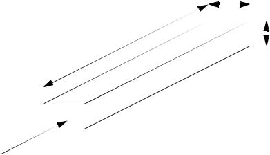
A design techniques using strain gages is to design a part with a narrowed neck to mount the strain gage on, as shown in Figure 23.20. In the narrow neck the strain is proportional to the load on the member, so it may be used to measure force. These parts are often called load cells.
mounted in narrow section to increase strain effect
F |
|
|
|
|
|
|
|
|
|
F |
|
|
|
|
|
|
|
|
|
|
|
|
|
|
|
|
|
|
|
|
|
|
|
|
|
|
|
|
|
|
|
|
|
|
|
|
|
Figure 23.20 Using a Narrow to Increase Strain
Strain gauges are inexpensive, and can be used to measure a wide range of stresses with accuracies under 1%. Gages require calibration before each use. This often involves making a reading with no load, or a known load applied. An example application includes using strain gages to measure die forces during stamping to estimate when maintenance is needed.
23.2.4.2 - Piezoelectric
When a crystal undergoes strain it displaces a small amount of charge. In other words, when the distance between atoms in the crystal lattice changes some electrons are forced out or drawn in. This also changes the capacitance of the crystal. This is known as

continuous sensors - 23.19
the Piezoelectric effect. Figure 23.21 shows the relationships for a crystal undergoing a linear deformation. The charge generated is a function of the force applied, the strain in the material, and a constant specific to the material. The change in capacitance is proportional to the change in the thickness.
|
ε ab |
d |
C = |
-------- |
---- |
c |
i = ε gdtF |
where,
F
b
+
q
-
c |
a |
|
|
|
F |
C = capacitance change
a, b, c = geometry of material
ε = dielectric constant (quartz typ. 4.06*10**-11 F/m)
i = current generated
F = force applied
g = constant for material (quartz typ. 50*10**-3 Vm/N)
E = Youngs modulus (quartz typ. 8.6*10**10 N/m**2)
Figure 23.21 The Piezoelectric Effect
These crystals are used for force sensors, but they are also used for applications such as microphones and pressure sensors. Applying an electrical charge can induce strain, allowing them to be used as actuators, such as audio speakers.
When using piezoelectric sensors charge amplifiers are needed to convert the small amount of charge to a larger voltage. These sensors are best suited to dynamic measurements, when used for static measurements they tend to drift or slowly lose charge, and the signal value will change.