


 Va
Va
continuous actuators - 24.8
 L1
L1
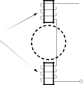
stator windings
rotor
Neut.
Figure 24.7 A 2 Pole Single Phase AC Motor

continuous actuators - 24.9
L2
L1
L3 
Neut.
Neut.
Neut.
Figure 24.8 A 6 Pole 3-Phase AC Motor
•The number of windings (poles) can be an integer multiple of the number of phases of power. More poles results in a lower rotation of the motor.
•Rotor types for induction motors are listed below. Their function is to intersect changing magnetic fields from the stator. The changing field induces currents in the rotor. These currents in turn set up magnetic fields that oppose fields from the stator, generating a torque.
Squirrel cage - has the shape of a wheel with end caps and bars Wound Rotor - the rotor has coils wound. These may be connected to
external contacts via commutator
• Induction motors require slip. If the motor turns at the precise speed of the stator field, it will not see a changing magnetic field. The result would be a collapse of the rotor magnetic field. As a result an induction motor always turns slightly slower than the stator field. The difference is called the slip. This is typically a few percent. As the motor is loaded the slip will increase until the motor stalls.

continuous actuators - 24.10
An induction motor has the windings on the stator. The rotor is normally a squirrel cage design. The squirrel cage is a cast aluminum core that when exposed to a changing magnetic field will set up an opposing field. When an AC voltage is applied to the stator coils an AC magnetic field is created, the squirrel cage sets up an opposing magnetic field and the resulting torque causes the motor to turn.
The motor will turn at a frequency close to that of the applied voltage, but there is always some slip. It is possible to control the speed of the motor by controlling the frequency of the AC voltage. Synchronous motor drives control the speed of the motors by synthesizing a variable frequency AC waveform, as shown in Figure 24.9.
Controller
Figure 24.9 AC Motor Speed Control
These drives should be used for applications that only require a single rotational direction. The torque speed curve for a typical induction motor is shown in Figure 24.10. When the motor is used with a fixed frequency AC source the synchronous speed of the motor will be the frequency of AC voltage divided by the number of poles in the motor. The motor actually has the maximum torque below the synchronous speed. For example a motor 2 pole motor might have a synchronous speed of (2*60*60/2) 3600 RPM, but be rated for 3520 RPM. When a feedback controller is used the issue of slip becomes insignificant.


 speed
speed
 speed
speed
 speed
speed
 speed
speedcontinuous actuators - 24.12
•Wound rotor induction motors use external resistors. varying the resistance allows the motors torque speed curve to vary. As the resistance value is increased the motor torque speed curve shifts from the Class A to Class D shapes.
•The figure below shows the relationship between the motor speed and applied power, slip, and number of poles. An ideal motor with no load would have a slip of 0%.
RPM = f---120------- |
1 – |
------S------- |
|
|
|
p |
|
100% |
|
where, |
= power frequency (60Hz typ.) |
|||
f |
||||
p |
= |
number of poles (2, 4, 6, etc...) |
||
RPM = motor speed in rotations per minute
S= motor slip
•Single phase AC motors can run in either direction. To compensate for this a shading pole is used on the stator windings. It basically acts as an inductor to one side of the field which slows the filed buildup and collapse. The result is that the field strength seems to naturally rotate.
•Thermal protection is normally used in motors to prevent overheating.
•Universal motors were presented earlier for DC applications, but they can also be used for AC power sources. This is because the field polarity in the rotor and stator both reverse as the AC current reverses.
•Synchronous motors are different from induction motors in that they are designed to rotate at the frequency of the fields, in other words there is no slip.
•Synchronous motors use generated fields in the rotor to oppose the stators field.
•Starting AC motors can be hard because of the low torque at low speeds. To deal with this a switching arrangement is often used. At low speeds other coils or capacitors are connected into the circuits. At higher speeds centrifugal switches disconnect these and the motor behavior switches.
continuous actuators - 24.13
• Single phase induction motors are typically used for loads under 1HP. Various types (based upon their starting and running modes) are,
-split phase - there are two windings on the motor. A starting winding is used to provide torque at lower speeds.
-capacitor run -
-capacitor start
-capacitor start and run
-shaded pole - these motors use a small offset coil (such as a single copper winding) to encourage the field buildup to occur asymmetrically. These motors are for low torque applications much less than 1HP.
-universal motors (also used with DC) have a wound rotor and stator that are connected in series.
