

plc electrical - 31.1
31. ELECTRICAL DESIGN AND CONSTRUCTION
Topics:
•Electrical wiring issues; cabinet wiring and layout, grounding, shielding and inductive loads
•Enclosures
Objectives:
• To learn the major issues in designing controllers including; electrical schematics, panel layout, grounding, shielding, enclosures.
31.1 INTRODUCTION
It is uncommon for engineers to build their own controller designs. For example, once the electrical designs are complete, they must be built by an electrician. Therefore, it is your responsibility to effectively communicate your design intentions to the electricians through drawings. In some factories, the electricians also enter the ladder logic and do debugging. This chapter discusses the design issues in implementation that must be considered by the designer.
31.2 ELECTRICAL WIRING DIAGRAMS
In an industrial setting a PLC is not simply "plugged into a wall socket". The electrical design for each machine must include at least the following components.
transformers - to step down AC supply voltages to lower levels
power contacts - to manually enable/disable power to the machine with e-stop buttons
terminals - to connect devices
fuses or breakers - will cause power to fail if too much current is drawn grounding - to provide a path for current to flow when there is an electrical fault enclosure - to protect the equipment, and users from accidental contact
A control system will normally use AC and DC power at different voltage levels. Control cabinets are often supplied with single phase AC at 220/440/550V, or two phase AC at 220/440Vac, or three phase AC at 330/550V. This power must be dropped down to a
plc electrical - 31.2
lower voltage level for the controls and DC power supplies. 110Vac is common in North America, and 220Vac is common in Europe and the Commonwealth countries. It is also common for a controls cabinet to supply a higher voltage to other equipment, such as motors.
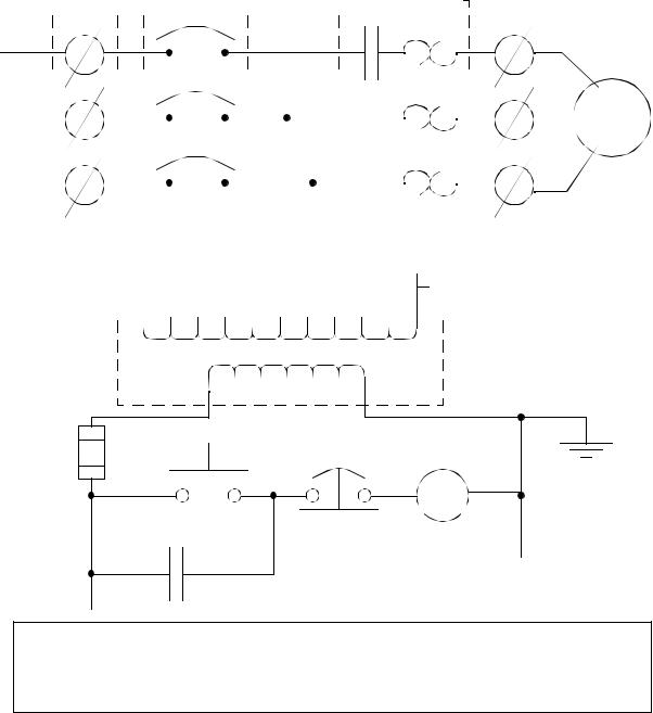
An example of a wiring diagram for a motor controller is shown in Figure 31.1 (note: the symbols are discussed in detail later). Dashed lines indicate a single purchased component. This system uses 3 phase AC power (L1, L2 and L3) connected to the terminals. The three phases are then connected to a power interrupter. Next, all three phases are supplied to a motor starter that contains three contacts, M, and three thermal overload relays (breakers). The contacts, M, will be controlled by the coil, M. The output of the motor starter goes to a three phase AC motor. Power is supplied by connecting a step down transformer to the control electronics by connecting to phases L2 and L3. The lower voltage is then used to supply power to the left and right rails of the ladder below. The neutral rail is also grounded. The logic consists of two push buttons. The start push button is normally open, so that if something fails the motor cannot be started. The stop push button is normally closed, so that if a wire or connection fails the system halts safely. The system controls the motor starter coil M, and uses a spare contact on the starter, M, to seal in the motor stater.
plc electrical - 31.3
terminals |
|
power interrupter |
|
|
motor starter |
|||||||||||||||||||||||||
|
|
|
|
|
|
|
|
|
|
|
|
|
|
|
|
|
|
|
|
|
|
|
|
|
|
|
|
|
|
|
|
|
|
|
|
|
|
|
|
|
|
|
|
|
|
|
|
|
|
|
|
|
|
|
|
|
|
|
|
|
|
M
L1
L2 |
|
|
|
|
|
|
|
|
|
|
|
|
|
|
|
|
|
|
|
|
|
|
|
|
|
|
|
|
|
|
|
|
|
|
|
|
|
|
|
|
|
|
|
|
|
|
|
|
M |
|
|
|
|
|
|
|
|
|
|
|
|
|
|
|
|
|
|
|
|
|
|
|
motor |
||
|
|
|
|
|
|
|
|
|
|
|
|
|
|
|
|
||||||||||||||||||||||||||||||||||||||||||||||||||||||||||||
|
|
|
|
|
|
|
|
|
|
|
|
|
|
|
|
|
|
|
|
|
|
|
|
|
|
|
|
|
|
|
|
||||||||||||||||||||||||||||||||||||||||||||
|
|
|
|
|
|
|
|
|
|
|
|
|
|
|
|
|
|
|
|
|
|
|
|
|
|
|
|
|
|
|
|
|
|
|
|
|
|
|
|
|
|
|
|
|
|
|
|
|
|
|
|
|
|
|
|
|
|
|
|
|
|
|
|
|
|
|
|
|
|
|
|
|
|
||
|
|
|
|
|
|
|
|
|
|
|
|
|
|
|
|
|
|
|
|
|
|
|
|
|
|
|
|
|
|
|
|
|
|
|
|
|
|
|
|
|
|
|
|
|
|
|
|
|
|
|
|
|
|
|
|
|
|
|
|
|
|
|
|
|
|
|
|
3 phase |
|||||||
|
|
|
|
|
|
|
|
|
|
|
|
|
|
|
|
|
|
|
|
|
|
|
|
|
|
|
|
|
|
|
|
|
|
|
|
|
|
|
|
|
|
|
|
|
|
|
|
|
|
|
|
|
|
|
|
|
|
|
|
|
|
|
|
|
|
|
|
|
|
|
|
|
|
|
|
|
|
|
|
|
|
|
|
|
|
|
|
|
|
|
|
|
|
|
|
|
|
|
|
|
|
|
|
|
|
|
|
|
|
|
|
|
|
|
|
|
|
|
|
|
|
|
|
|
|
|
|
|
|
|
|
|
|
|
|
|
|
|
|
|
|
|
|
|
|
|
|
|
|
|
|
L3 |
|
|
|
|
|
|
|
|
|
|
|
|
|
|
|
|
|
|
|
|
|
|
|
|
|
|
|
|
|
|
|
|
|
|
|
|
|
|
|
|
|
|
|
|
|
|
|
|
M |
|
|
|
|
|
|
|
|
|
|
|
|
|
|
|
|
|
|
|
|
|
|
|
AC |
||
|
|
|
|
|
|
|
|
|
|
|
|
|
|
|
|
|
|
|
|
|
|
|
|
|
|
|
|
|
|
|
|
|
|
|
|
|
|
|
|
|
|
|
|
|
|
|
|
|
|
|
|
|
|
|
|
|
|
|
|
|
|
|
|
|
|
|
|
|
|
|
|||||
|
|
|
|
|
|
|
|
|
|
|
|
|
|
|
|
|
|
|
|
|
|
|
|
|
|
|
|
|
|
|
|
|
|
|
|
|
|
|
|
|
|
|
|
|
|
|
|
|
|
|
|
|
|
|
|
|
|
|
|
|
|
|
|
|
|
|
|
|
|
|
|||||
|
|
|
|
|
|
|
|
|
|
|
|
|
|
|
|
|
|
|
|
|
|
|
|
|
|
|
|
|
|
|
|
|
|
|
|
|
|
|
|
|
|
|
|
|
|
|
|
|
|
|
|
|
|
|
|
|
|
|
|
|
|
|
|
|
|
|
|
|
|
|
|||||
|
|
|
|
|
|
|
|
|
|
|
|
|
|
|
|
|
|
|
|
|
|
|
|
|
|
|
|
|
|
|
|
|
|
|
|
|
|
|
|
|
|
|
|
|
|
|
|
|
|
|
|
|
|
|
|
|
|
|
|
|
|
|
|
|
|
|
|
|
|||||||
|
|
|
|
|
|
|
|
|
|
|
|
|
|
|
|
|
|
|
|
|
|
|
|
|
|
|
|
|
|
|
|
|
|
|
|
|
|
|
|
|
|
|
|
|
|
|
|
|
|
|
|
|
|
|
|
|
|
|
|
|
|
|
|
|
|
||||||||||
|
|
|
|
|
|
|
|
|
|
|
|
|
|
|
|
|
|
|
|
|
|
|
|
|
|
|
|
|
|
|
|
|
|
|
|
|
|
|
|
|
|
|
|
|
|
|
|
|
|
|
|
|
|
|
|
|
|
|
|
|
|
|
|
|
|
|
|
|
|
|
|
|
|
|
|
|
|
|
|
|
|
|
|
|
|
|
|
|
|
|
|
|
|
|
|
|
|
|
|
|
|
|
|
|
|
|
|
|
|
|
|
|
|
|
|
|
|
|
|
|
|
|
|
|
|
|
|
|
|
|
|
|
|
|
|
|
|
|
|
|
|
|
|
|
|
|
|
|
|
|
|
|
|
|
|
|
|
|
|
|
|
|
|
|
|
|
|
|
|
|
|
|
|
|
|
|
|
|
|
|
|
|
|
|
|
|
|
|
|
|
|
|
|
|
|
|
|
|
|
|
|
|
|
|
|
|
|
|
|
|
|
|
|
|
|
|
|
|
|
|
|
|
|
|
|
|
|
|
|
|
|
|
|
|
|
|
|
|
|
|
|
|
|
|
|
|
|
|
|
|
|
|
|
|
|
|
|
|
|
|
|
|
|
|
|
|
|
|
|
|
|
|
|
|
|
|
|
|
|
|
|
|
|
|
|
|
|
|
|
|
|
|
|
|
|
|
|
|
|
|
|
|
|
|
|
|
|
|
|
|
|
|
|
|
|
|
|
|
|
|
|
|
|
|
|
|
|
|
|
|
|
|
|
|
|
|
|
|
|
|
|
|
|
|
|
|
|
|
|
|
|
|
|
|
|
|
|
|
|
|
|
|
|
|
|
|
|
|
|
|
|
|
|
|
|
|
|
|
|
|
|
|
|
|
|
|
|
|
|
|
|
|
|
|
|
|
|
|
|
|
|
|
|
|
|
|
|
|
|
|
|
|
|
|
|
|
|
|
|
|
|
|
|
|
|
|
|
|
|
|
|
|
|
|
|
|
|
|
|
|
|
|
|
|
|
|
|
|
|
|
|
|
|
|
|
|
|
|
|
|
|
|
|
|
|
|
|
|
|
|
|
|
|
|
|
|
|
|
|
|
|
|
|
|
|
|
|
|
|
|
|
|
|
|
|
|
|
|
|
|
|
|
|
|
|
|
|
|
|
|
|
|
|
|
|
|
|
|
|
|
|
|
|
|
|
|
|
|
|
|
|
|
|
|
|
|
|
|
|
|
|
|
|
|
|
|
|
|
|
|
|
|
|
|
|
|
|
|
|
|
|
|
|
|
|
|
|
|
|
|
|
|
|
|
|
|
|
|
|
|
|
|
|
|
|
|
|
|
|
|
|
|
|
|
|
|
|
|
|
|
|
|
|
|
|
|
|
|
|
|
|
|
|
|
|
|
|
|
|
|
|
|
|
|
|
|
|
|
|
|
|
|
|
|
|
|
|
|
|
|
|
|
|
|
|
|
|
|
|
|
|
|
|
|
|
|
|
|
|
|
|
|
|
|
|
|
|
|
|
|
|
|
|
|
|
|
|
|
|
|
|
|
|
|
|
|
|
|
|
|
|
|
|
|
|
|
|
|
|
|
|
|
|
|
|
|
|
|
|
|
|
|
|
|
|
|
|
|
|
|
|
|
|
|
|
|
|
|
|
|
|
|
|
|
|
|
|
|
|
|
|
|
|
|
|
|
|
|
|
|
|
|
|
|
|
|
|
|
|
|
|
|
|
|
|
|
|
|
|
|
|
|
|
|
|
|
|
|
|
|
|
|
|
|
|
|
|
|
|
|
|
|
|
|
|
|
|
|
|
|
|
|
|
|
|
|
|
|
|
|
|
|
|
|
|
|
|
|
|
|
|
|
|
|
|
|
|
|
|
|
|
|
|
|
|
|
|
|
|
|
|
|
|
|
|
|
|
|
|
|
|
|
|
|
|
|
|
|
|
|
|
|
|
|
|
|
|
|
|
|
|
|
|
|
|
|
|
|
|
|
|
|
|
|
|
|
|
|
|
|
|
|
|
|
|
|
|
|
|
|
|
|
|
|
|
|
|
|
|
|
|
step down transformer
0010 |
|
|
start |
|
stop |
0020 |
M |
|
M |
0030 |
|
Aside: The voltage for the step down transformer is connected between phases L2 and L3. This will increase the effective voltage by 50% of the magnitude of the voltage on a single phase.
Figure 31.1 A Motor Controller Schematic
The diagram also shows numbering for the wires in the device. This is essential for industrial control systems that may contain hundreds or thousands of wires. These numbering schemes are often particular to each facility, but there are tools to help make wire labels that will appear in the final controls cabinet.
plc electrical - 31.4
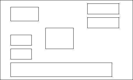
Once the electrical design is complete, a layout for the controls cabinet is developed, as shown in Figure 31.2. The physical dimensions of the devices must be considered, and adequate space is needed to run wires between components. In the cabinet the AC power would enter at the terminal block, and be connected to the main breaker. It would then be connected to the contactors and overload relays that constitute the motor starter. Two of the phases are also connected to the transformer to power the logic. The start and stop buttons are at the left of the box (note: normally these are mounted elsewhere, and a separate layout drawing would be needed).
Contactors
Main
Breaker
Overload
Transformer
Start
Stop
Terminal Block
Figure 31.2 A Physical Layout for the Control Cabinet
The final layout in the cabinet might look like the one shown in Figure 31.3.

plc electrical - 31.5
L1 |
L2 |
L3 |
|
start |
|
|
stop |
|
|
|
|
|
|
|
|
|
|
|
|
|
|
|
|
|
|
|
|
|
|
motor |
|
|
|
|
|
|
|
|
|
|
|
|
|
|
|
|
|
|
|
|
|
3 phase |
|
3 phase AC |
|
|
|
||||||
|
|
|
|
AC |
||||||
Figure 31.3 Final Panel Wiring |
|
|
|
|
||||||
plc electrical - 31.6
When being built the system will follow certain standards that may be company policy, or legal requirements. This often includes items such as;
hold downs - the will secure the wire so they don’t move labels - wire labels help troubleshooting
strain reliefs - these will hold the wire so that it will not be pulled out of screw terminals
grounding - grounding wires may be needed on each metal piece for safety
A photograph of an industrial controls cabinet is shown in Figure 31.4.
Get a photo of a controls cabinet with
wire runs, terminal strip, buttons on panel front, etc
Figure 31.4 An Industrial Controls Cabinet
When including a PLC in the ladder diagram still remains. But, it does tend to become more complex. Figure 31.5 shows a schematic diagram for a PLC based motor control system, similar to the previous motor control example.
XXXXXXXXXXXXXX This figure shows the E-stop wired to cutoff power to all of the devices in the circuit, including the PLC. All critical safety functions should be hardwired this way.