- •1.1 TODO LIST
- •2. PROGRAMMABLE LOGIC CONTROLLERS
- •2.1 INTRODUCTION
- •2.1.1 Ladder Logic
- •2.1.2 Programming
- •2.1.3 PLC Connections
- •2.1.4 Ladder Logic Inputs
- •2.1.5 Ladder Logic Outputs
- •2.2 A CASE STUDY
- •2.3 SUMMARY
- •2.4 PRACTICE PROBLEMS
- •2.5 PRACTICE PROBLEM SOLUTIONS
- •2.6 ASSIGNMENT PROBLEMS
- •3. PLC HARDWARE
- •3.1 INTRODUCTION
- •3.2 INPUTS AND OUTPUTS
- •3.2.1 Inputs
- •3.2.2 Output Modules
- •3.3 RELAYS
- •3.4 A CASE STUDY
- •3.5 ELECTRICAL WIRING DIAGRAMS
- •3.5.1 JIC Wiring Symbols
- •3.6 SUMMARY
- •3.7 PRACTICE PROBLEMS
- •3.8 PRACTICE PROBLEM SOLUTIONS
- •3.9 ASSIGNMENT PROBLEMS
- •4. LOGICAL SENSORS
- •4.1 INTRODUCTION
- •4.2 SENSOR WIRING
- •4.2.1 Switches
- •4.2.2 Transistor Transistor Logic (TTL)
- •4.2.3 Sinking/Sourcing
- •4.2.4 Solid State Relays
- •4.3 PRESENCE DETECTION
- •4.3.1 Contact Switches
- •4.3.2 Reed Switches
- •4.3.3 Optical (Photoelectric) Sensors
- •4.3.4 Capacitive Sensors
- •4.3.5 Inductive Sensors
- •4.3.6 Ultrasonic
- •4.3.7 Hall Effect
- •4.3.8 Fluid Flow
- •4.4 SUMMARY
- •4.5 PRACTICE PROBLEMS
- •4.6 PRACTICE PROBLEM SOLUTIONS
- •4.7 ASSIGNMENT PROBLEMS
- •5. LOGICAL ACTUATORS
- •5.1 INTRODUCTION
- •5.2 SOLENOIDS
- •5.3 VALVES
- •5.4 CYLINDERS
- •5.5 HYDRAULICS
- •5.6 PNEUMATICS
- •5.7 MOTORS
- •5.8 COMPUTERS
- •5.9 OTHERS
- •5.10 SUMMARY
- •5.11 PRACTICE PROBLEMS
- •5.12 PRACTICE PROBLEM SOLUTIONS
- •5.13 ASSIGNMENT PROBLEMS
- •6. BOOLEAN LOGIC DESIGN
- •6.1 INTRODUCTION
- •6.2 BOOLEAN ALGEBRA
- •6.3 LOGIC DESIGN
- •6.3.1 Boolean Algebra Techniques
- •6.4 COMMON LOGIC FORMS
- •6.4.1 Complex Gate Forms
- •6.4.2 Multiplexers
- •6.5 SIMPLE DESIGN CASES
- •6.5.1 Basic Logic Functions
- •6.5.2 Car Safety System
- •6.5.3 Motor Forward/Reverse
- •6.5.4 A Burglar Alarm
- •6.6 SUMMARY
- •6.7 PRACTICE PROBLEMS
- •6.8 PRACTICE PROBLEM SOLUTIONS
- •6.9 ASSIGNMENT PROBLEMS
- •7. KARNAUGH MAPS
- •7.1 INTRODUCTION
- •7.2 SUMMARY
- •7.3 PRACTICE PROBLEMS
- •7.4 PRACTICE PROBLEM SOLUTIONS
- •7.5 ASSIGNMENT PROBLEMS
- •8. PLC OPERATION
- •8.1 INTRODUCTION
- •8.2 OPERATION SEQUENCE
- •8.2.1 The Input and Output Scans
- •8.2.2 The Logic Scan
- •8.3 PLC STATUS
- •8.4 MEMORY TYPES
- •8.5 SOFTWARE BASED PLCS
- •8.6 SUMMARY
- •8.7 PRACTICE PROBLEMS
- •8.8 PRACTICE PROBLEM SOLUTIONS
- •8.9 ASSIGNMENT PROBLEMS
- •9. LATCHES, TIMERS, COUNTERS AND MORE
- •9.1 INTRODUCTION
- •9.2 LATCHES
- •9.3 TIMERS
- •9.4 COUNTERS
- •9.5 MASTER CONTROL RELAYS (MCRs)
- •9.6 INTERNAL RELAYS
- •9.7 DESIGN CASES
- •9.7.1 Basic Counters And Timers
- •9.7.2 More Timers And Counters
- •9.7.3 Deadman Switch
- •9.7.4 Conveyor
- •9.7.5 Accept/Reject Sorting
- •9.7.6 Shear Press
- •9.8 SUMMARY
- •9.9 PRACTICE PROBLEMS
- •9.10 PRACTICE PROBLEM SOLUTIONS
- •9.11 ASSIGNMENT PROBLEMS
- •10. STRUCTURED LOGIC DESIGN
- •10.1 INTRODUCTION
- •10.2 PROCESS SEQUENCE BITS
- •10.3 TIMING DIAGRAMS
- •10.4 DESIGN CASES
- •10.5 SUMMARY
- •10.6 PRACTICE PROBLEMS
- •10.7 PRACTICE PROBLEM SOLUTIONS
- •10.8 ASSIGNMENT PROBLEMS
- •11. FLOWCHART BASED DESIGN
- •11.1 INTRODUCTION
- •11.2 BLOCK LOGIC
- •11.3 SEQUENCE BITS
- •11.4 SUMMARY
- •11.5 PRACTICE PROBLEMS
- •11.6 PRACTICE PROBLEM SOLUTIONS
- •11.7 ASSIGNMENT PROBLEMS
- •12. STATE BASED DESIGN
- •12.1 INTRODUCTION
- •12.1.1 State Diagram Example
- •12.1.2 Conversion to Ladder Logic
- •12.1.2.1 - Block Logic Conversion
- •12.1.2.2 - State Equations
- •12.1.2.3 - State-Transition Equations
- •12.2 SUMMARY
- •12.3 PRACTICE PROBLEMS
- •12.4 PRACTICE PROBLEM SOLUTIONS
- •12.5 ASSIGNMENT PROBLEMS
- •13. NUMBERS AND DATA
- •13.1 INTRODUCTION
- •13.2 NUMERICAL VALUES
- •13.2.1 Binary
- •13.2.1.1 - Boolean Operations
- •13.2.1.2 - Binary Mathematics
- •13.2.2 Other Base Number Systems
- •13.2.3 BCD (Binary Coded Decimal)
- •13.3 DATA CHARACTERIZATION
- •13.3.1 ASCII (American Standard Code for Information Interchange)
- •13.3.2 Parity
- •13.3.3 Checksums
- •13.3.4 Gray Code
- •13.4 SUMMARY
- •13.5 PRACTICE PROBLEMS
- •13.6 PRACTICE PROBLEM SOLUTIONS
- •13.7 ASSIGNMENT PROBLEMS
- •14. PLC MEMORY
- •14.1 INTRODUCTION
- •14.2 MEMORY ADDRESSES
- •14.3 PROGRAM FILES
- •14.4 DATA FILES
- •14.4.1 User Bit Memory
- •14.4.2 Timer Counter Memory
- •14.4.3 PLC Status Bits (for PLC-5s and Micrologix)
- •14.4.4 User Function Control Memory
- •14.4.5 Integer Memory
- •14.4.6 Floating Point Memory
- •14.5 SUMMARY
- •14.6 PRACTICE PROBLEMS
- •14.7 PRACTICE PROBLEM SOLUTIONS
- •14.8 ASSIGNMENT PROBLEMS
- •15. LADDER LOGIC FUNCTIONS
- •15.1 INTRODUCTION
- •15.2 DATA HANDLING
- •15.2.1 Move Functions
- •15.2.2 Mathematical Functions
- •15.2.3 Conversions
- •15.2.4 Array Data Functions
- •15.2.4.1 - Statistics
- •15.2.4.2 - Block Operations
- •15.3 LOGICAL FUNCTIONS
- •15.3.1 Comparison of Values
- •15.3.2 Boolean Functions
- •15.4 DESIGN CASES
- •15.4.1 Simple Calculation
- •15.4.2 For-Next
- •15.4.3 Series Calculation
- •15.4.4 Flashing Lights
- •15.5 SUMMARY
- •15.6 PRACTICE PROBLEMS
- •15.7 PRACTICE PROBLEM SOLUTIONS
- •15.8 ASSIGNMENT PROBLEMS
- •16. ADVANCED LADDER LOGIC FUNCTIONS
- •16.1 INTRODUCTION
- •16.2 LIST FUNCTIONS
- •16.2.1 Shift Registers
- •16.2.2 Stacks
- •16.2.3 Sequencers
- •16.3 PROGRAM CONTROL
- •16.3.1 Branching and Looping
- •16.3.2 Fault Detection and Interrupts
- •16.4 INPUT AND OUTPUT FUNCTIONS
- •16.4.1 Immediate I/O Instructions
- •16.4.2 Block Transfer Functions
- •16.5 DESIGN TECHNIQUES
- •16.5.1 State Diagrams
- •16.6 DESIGN CASES
- •16.6.1 If-Then
- •16.6.2 Traffic Light
- •16.7 SUMMARY
- •16.8 PRACTICE PROBLEMS
- •16.9 PRACTICE PROBLEM SOLUTIONS
- •16.10 ASSIGNMENT PROBLEMS
- •17. OPEN CONTROLLERS
- •17.1 INTRODUCTION
- •17.3 OPEN ARCHITECTURE CONTROLLERS
- •17.4 SUMMARY
- •17.5 PRACTICE PROBLEMS
- •17.6 PRACTICE PROBLEM SOLUTIONS
- •17.7 ASSIGNMENT PROBLEMS
- •18. INSTRUCTION LIST PROGRAMMING
- •18.1 INTRODUCTION
- •18.2 THE IEC 61131 VERSION
- •18.3 THE ALLEN-BRADLEY VERSION
- •18.4 SUMMARY
- •18.5 PRACTICE PROBLEMS
- •18.6 PRACTICE PROBLEM SOLUTIONS
- •18.7 ASSIGNMENT PROBLEMS
- •19. STRUCTURED TEXT PROGRAMMING
- •19.1 INTRODUCTION
- •19.2 THE LANGUAGE
- •19.3 SUMMARY
- •19.4 PRACTICE PROBLEMS
- •19.5 PRACTICE PROBLEM SOLUTIONS
- •19.6 ASSIGNMENT PROBLEMS
- •20. SEQUENTIAL FUNCTION CHARTS
- •20.1 INTRODUCTION
- •20.2 A COMPARISON OF METHODS
- •20.3 SUMMARY
- •20.4 PRACTICE PROBLEMS
- •20.5 PRACTICE PROBLEM SOLUTIONS
- •20.6 ASSIGNMENT PROBLEMS
- •21. FUNCTION BLOCK PROGRAMMING
- •21.1 INTRODUCTION
- •21.2 CREATING FUNCTION BLOCKS
- •21.3 DESIGN CASE
- •21.4 SUMMARY
- •21.5 PRACTICE PROBLEMS
- •21.6 PRACTICE PROBLEM SOLUTIONS
- •21.7 ASSIGNMENT PROBLEMS
- •22. ANALOG INPUTS AND OUTPUTS
- •22.1 INTRODUCTION
- •22.2 ANALOG INPUTS
- •22.2.1 Analog Inputs With a PLC
- •22.3 ANALOG OUTPUTS
- •22.3.1 Analog Outputs With A PLC
- •22.3.2 Pulse Width Modulation (PWM) Outputs
- •22.3.3 Shielding
- •22.4 DESIGN CASES
- •22.4.1 Process Monitor
- •22.5 SUMMARY
- •22.6 PRACTICE PROBLEMS
- •22.7 PRACTICE PROBLEM SOLUTIONS
- •22.8 ASSIGNMENT PROBLEMS
- •23. CONTINUOUS SENSORS
- •23.1 INTRODUCTION
- •23.2 INDUSTRIAL SENSORS
- •23.2.1 Angular Displacement
- •23.2.1.1 - Potentiometers
- •23.2.2 Encoders
- •23.2.2.1 - Tachometers
- •23.2.3 Linear Position
- •23.2.3.1 - Potentiometers
- •23.2.3.2 - Linear Variable Differential Transformers (LVDT)
- •23.2.3.3 - Moire Fringes
- •23.2.3.4 - Accelerometers
- •23.2.4 Forces and Moments
- •23.2.4.1 - Strain Gages
- •23.2.4.2 - Piezoelectric
- •23.2.5 Liquids and Gases
- •23.2.5.1 - Pressure
- •23.2.5.2 - Venturi Valves
- •23.2.5.3 - Coriolis Flow Meter
- •23.2.5.4 - Magnetic Flow Meter
- •23.2.5.5 - Ultrasonic Flow Meter
- •23.2.5.6 - Vortex Flow Meter
- •23.2.5.7 - Positive Displacement Meters
- •23.2.5.8 - Pitot Tubes
- •23.2.6 Temperature
- •23.2.6.1 - Resistive Temperature Detectors (RTDs)
- •23.2.6.2 - Thermocouples
- •23.2.6.3 - Thermistors
- •23.2.6.4 - Other Sensors
- •23.2.7 Light
- •23.2.7.1 - Light Dependant Resistors (LDR)
- •23.2.8 Chemical
- •23.2.8.2 - Conductivity
- •23.2.9 Others
- •23.3 INPUT ISSUES
- •23.4 SENSOR GLOSSARY
- •23.5 SUMMARY
- •23.6 REFERENCES
- •23.7 PRACTICE PROBLEMS
- •23.8 PRACTICE PROBLEM SOLUTIONS
- •23.9 ASSIGNMENT PROBLEMS
- •24. CONTINUOUS ACTUATORS
- •24.1 INTRODUCTION
- •24.2 ELECTRIC MOTORS
- •24.2.1 Basic Brushed DC Motors
- •24.2.2 AC Motors
- •24.2.3 Brushless DC Motors
- •24.2.4 Stepper Motors
- •24.2.5 Wound Field Motors
- •24.3 HYDRAULICS
- •24.4 OTHER SYSTEMS
- •24.5 SUMMARY
- •24.6 PRACTICE PROBLEMS
- •24.7 PRACTICE PROBLEM SOLUTIONS
- •24.8 ASSIGNMENT PROBLEMS
- •25. CONTINUOUS CONTROL
- •25.1 INTRODUCTION
- •25.2 CONTROL OF LOGICAL ACTUATOR SYSTEMS
- •25.3 CONTROL OF CONTINUOUS ACTUATOR SYSTEMS
- •25.3.1 Block Diagrams
- •25.3.2 Feedback Control Systems
- •25.3.3 Proportional Controllers
- •25.3.4 PID Control Systems
- •25.4 DESIGN CASES
- •25.4.1 Oven Temperature Control
- •25.4.2 Water Tank Level Control
- •25.5 SUMMARY
- •25.6 PRACTICE PROBLEMS
- •25.7 PRACTICE PROBLEM SOLUTIONS
- •25.8 ASSIGNMENT PROBLEMS
- •26. FUZZY LOGIC
- •26.1 INTRODUCTION
- •26.2 COMMERCIAL CONTROLLERS
- •26.3 REFERENCES
- •26.4 SUMMARY
- •26.5 PRACTICE PROBLEMS
- •26.6 PRACTICE PROBLEM SOLUTIONS
- •26.7 ASSIGNMENT PROBLEMS
- •27. SERIAL COMMUNICATION
- •27.1 INTRODUCTION
- •27.2 SERIAL COMMUNICATIONS
- •27.2.1.1 - ASCII Functions
- •27.3 PARALLEL COMMUNICATIONS
- •27.4 DESIGN CASES
- •27.4.1 PLC Interface To a Robot
- •27.5 SUMMARY
- •27.6 PRACTICE PROBLEMS
- •27.7 PRACTICE PROBLEM SOLUTIONS
- •27.8 ASSIGNMENT PROBLEMS
- •28. NETWORKING
- •28.1 INTRODUCTION
- •28.1.1 Topology
- •28.1.2 OSI Network Model
- •28.1.3 Networking Hardware
- •28.1.4 Control Network Issues
- •28.2 NETWORK STANDARDS
- •28.2.1 Devicenet
- •28.2.2 CANbus
- •28.2.3 Controlnet
- •28.2.4 Ethernet
- •28.2.5 Profibus
- •28.2.6 Sercos
- •28.3 PROPRIETARY NETWORKS
- •28.3.1 Data Highway
- •28.4 NETWORK COMPARISONS
- •28.5 DESIGN CASES
- •28.5.1 Devicenet
- •28.6 SUMMARY
- •28.7 PRACTICE PROBLEMS
- •28.8 PRACTICE PROBLEM SOLUTIONS
- •28.9 ASSIGNMENT PROBLEMS
- •29. INTERNET
- •29.1 INTRODUCTION
- •29.1.1 Computer Addresses
- •29.1.2 Phone Lines
- •29.1.3 Mail Transfer Protocols
- •29.1.4 FTP - File Transfer Protocol
- •29.1.5 HTTP - Hypertext Transfer Protocol
- •29.1.6 Novell
- •29.1.7 Security
- •29.1.7.1 - Firewall
- •29.1.7.2 - IP Masquerading
- •29.1.8 HTML - Hyper Text Markup Language
- •29.1.9 URLs
- •29.1.10 Encryption
- •29.1.11 Compression
- •29.1.12 Clients and Servers
- •29.1.13 Java
- •29.1.14 Javascript
- •29.1.16 ActiveX
- •29.1.17 Graphics
- •29.2 DESIGN CASES
- •29.2.1 Remote Monitoring System
- •29.3 SUMMARY
- •29.4 PRACTICE PROBLEMS
- •29.5 PRACTICE PROBLEM SOLUTIONS
- •29.6 ASSIGNMENT PROBLEMS
- •30. HUMAN MACHINE INTERFACES (HMI)
- •30.1 INTRODUCTION
- •30.2 HMI/MMI DESIGN
- •30.3 DESIGN CASES
- •30.4 SUMMARY
- •30.5 PRACTICE PROBLEMS
- •30.6 PRACTICE PROBLEM SOLUTIONS
- •30.7 ASSIGNMENT PROBLEMS
- •31. ELECTRICAL DESIGN AND CONSTRUCTION
- •31.1 INTRODUCTION
- •31.2 ELECTRICAL WIRING DIAGRAMS
- •31.2.1 Selecting Voltages
- •31.2.2 Grounding
- •31.2.3 Wiring
- •31.2.4 Suppressors
- •31.2.5 PLC Enclosures
- •31.2.6 Wire and Cable Grouping
- •31.3 FAIL-SAFE DESIGN
- •31.4 SAFETY RULES SUMMARY
- •31.5 REFERENCES
- •31.6 SUMMARY
- •31.7 PRACTICE PROBLEMS
- •31.8 PRACTICE PROBLEM SOLUTIONS
- •31.9 ASSIGNMENT PROBLEMS
- •32. SOFTWARE ENGINEERING
- •32.1 INTRODUCTION
- •32.1.1 Fail Safe Design
- •32.2 DEBUGGING
- •32.2.1 Troubleshooting
- •32.2.2 Forcing
- •32.3 PROCESS MODELLING
- •32.4 PROGRAMMING FOR LARGE SYSTEMS
- •32.4.1 Developing a Program Structure
- •32.4.2 Program Verification and Simulation
- •32.5 DOCUMENTATION
- •32.6 COMMISIONING
- •32.7 REFERENCES
- •32.8 SUMMARY
- •32.9 PRACTICE PROBLEMS
- •32.10 PRACTICE PROBLEM SOLUTIONS
- •32.11 ASSIGNMENT PROBLEMS
- •33. SELECTING A PLC
- •33.1 INTRODUCTION
- •33.2 SPECIAL I/O MODULES
- •33.3 SUMMARY
- •33.4 PRACTICE PROBLEMS
- •33.5 PRACTICE PROBLEM SOLUTIONS
- •33.6 ASSIGNMENT PROBLEMS
- •34. FUNCTION REFERENCE
- •34.1 FUNCTION DESCRIPTIONS
- •34.1.1 General Functions
- •34.1.2 Program Control
- •34.1.3 Timers and Counters
- •34.1.4 Compare
- •34.1.5 Calculation and Conversion
- •34.1.6 Logical
- •34.1.7 Move
- •34.1.8 File
- •34.1.10 Program Control
- •34.1.11 Advanced Input/Output
- •34.1.12 String
- •34.2 DATA TYPES
- •35. COMBINED GLOSSARY OF TERMS
- •36. PLC REFERENCES
- •36.1 SUPPLIERS
- •36.2 PROFESSIONAL INTEREST GROUPS
- •36.3 PLC/DISCRETE CONTROL REFERENCES
- •37. GNU Free Documentation License
- •37.1 PREAMBLE
- •37.2 APPLICABILITY AND DEFINITIONS
- •37.3 VERBATIM COPYING
- •37.4 COPYING IN QUANTITY
- •37.5 MODIFICATIONS
- •37.6 COMBINING DOCUMENTS
- •37.7 COLLECTIONS OF DOCUMENTS
- •37.8 AGGREGATION WITH INDEPENDENT WORKS
- •37.9 TRANSLATION
- •37.10 TERMINATION
- •37.11 FUTURE REVISIONS OF THIS LICENSE
- •37.12 How to use this License for your documents
continuous sensors - 23.37
+V
R5
R1 |
R3 |
-
+
Vout
R2 |
|
|
|
|
|
|
R4 |
|
|
|
|
|
|
|
|
|
|
|
|
|
|
|
|
|
|
|
|
|
|
|
|
|
|
|
|
|
|
|
|
V |
out |
= V( R ) |
R2 |
|
|
1 |
+ |
1 |
+ |
1 |
– |
1 |
|
|
----------- |
----- |
----- |
----- |
----- |
||||||||||
|
5 |
R1 |
+ R2 R3 |
|
R4 |
|
R5 |
R3 |
|
|||||
|
|
|
|
|
|
|||||||||
or if R = R1 = R2 = R4 = R5 |
|
|
|
|
|
|||||||||
Vout |
= V ---R----- |
|
|
|
|
|
|
|
|
|
|
|
|
|
|
|
2R3 |
|
|
|
|
|
|
|
|
|
|
|
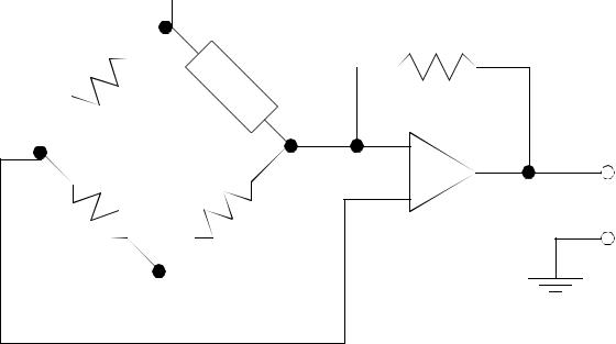
Figure 23.37 A Resistance to Voltage Amplifier
23.4 SENSOR GLOSSARY
Ammeter - A meter to indicate electrical current. It is normally part of a DMM Bellows - This is a flexible volumed that will expand or contract with a pressure change. This often looks like a cylinder with a large radius (typ. 2") but it is
very thin (type 1/4"). It can be set up so that when pressure changes, the displacement of one side can be measured to determine pressure.
Bourdon tube - Widely used industrial gage to measure pressure and vacuum. It resembles a crescent moon. When the pressure inside changes the moon shape will tend to straighten out. By measuring the displacement of the tip the pressure can be measured.
Chromatographic instruments - laboratory-type instruments used to analyze chemical compounds and gases.
Inductance-coil pulse generator - transducer used to measure rotational speed. Out-
continuous sensors - 23.38
put is pulse train.
Interferometers - These use the interference of light waves 180 degrees out of phase to determine distances. Typical sources of the monochromatic light required are lasers.
Linear-Variable-Differential transformer (LVDT) electromechanical transducer used to measure angular or linear displacement. Output is Voltage
Manometer - liquid column gage used widely in industry to measure pressure. Ohmmeter - meter to indicate electrical resistance
Optical Pyrometer - device to measure temperature of an object at high temperatures by sensing the brightness of an objects surface.
Orifice Plate - widely used flowmeter to indicate fluid flow rates
Photometric Transducers - a class of transducers used to sense light, including phototubes, photodiodes, phototransistors, and photoconductors.
Piezoelectric Accelerometer - Transducer used to measure vibration. Output is emf.
Pitot Tube - Laboratory device used to measure flow.
Positive displacement Flowmeter - Variety of transducers used to measure flow. Typical output is pulse train.
Potentiometer - instrument used to measure voltage
Pressure Transducers - A class of transducers used to measure pressure. Typical output is voltage. Operation of the transducer can be based on strain gages or other devices.
Radiation pyrometer - device to measure temperature by sensing the thermal radiation emitted from the object.
Resolver - this device is similar to an incremental encoder, except that it uses coils to generate magnetic fields. This is like a rotary transformer.
Strain Gage - Widely used to indicate torque, force, pressure, and other variables. Output is change in resistance due to strain, which can be converted into voltage.
Thermistor - Also called a resistance thermometer; an instrument used to measure temperature. Operation is based on change in resistance as a function of temperature.
Thermocouple - widely used temperature transducer based on the Seebeck effect, in which a junction of two dissimilar metals emits emf related to temperature.
Turbine Flowmeter - transducer to measure flow rate. Output is pulse train. Venturi Tube - device used to measure flow rates.
23.5SUMMARY
•Selection of continuous sensors must include issues such as accuracy and resolution.
•Angular positions can be measured with potentiometers and encoders (more accurate).
•Tachometers are useful for measuring angular velocity.
continuous sensors - 23.39
•Linear positions can be measured with potentiometers (limited accuracy), LVDTs (limited range), moire fringes (high accuracy).
•Accelerometers measure acceleration of masses.
•Strain gauges and piezoelectric elements measure force.
•Pressure can be measured indirectly with bellows and Bourdon tubes.
•Flow rates can be measured with Venturi valves and pitot tubes.
•Temperatures can be measured with RTDs, thermocouples, and thermistors.
•Input signals can be single ended for more inputs or double ended for more accuracy.
23.6REFERENCES
Bryan, L.A. and Bryan, E.A., Programmable Controllers; Theory and Implementation, Industrial Text Co., 1988.
Swainston, F., A Systems Approach to Programmable Controllers, Delmar Publishers Inc., 1992.
23.7 PRACTICE PROBLEMS
1.Name two types of inputs that would be analog input values (versus a digital value).
2.Search the web for common sensor manufacturers for 5 different types of continuous sensors. If possible identify prices for the units. Sensor manufacturers include (hyde park, banner, allen bradley, omron, etc.)
3.What is the resolution of an absolute optical encoder that has six binary tracks? nine tracks? twelve tracks?
4.Suggest a couple of methods for collecting data on the factory floor
5.If a thermocouple generates a voltage of 30mV at 800F and 40mV at 1000F, what voltage will be generated at 1200F?
6.A potentiometer is to be used to measure the position of a rotating robot link (as a voltage divider). The power supply connected across the potentiometer is 5.0 V, and the total wiper travel is 300 degrees. The wiper arm is directly connected to the rotational joint so that a given rotation of the joint corresponds to an equal rotation of the wiper arm.
a)If the joint is at 42 degrees, what voltage will be output from the potentiometer?
b)If the joint has been moved, and the potentiometer output is 2.765V, what is the position of the potentiometer?
7.A motor has an encoder mounted on it. The motor is driving a reducing gear box with a 50:1
continuous sensors - 23.40
ratio. If the position of the geared down shaft needs to be positioned to 0.1 degrees, what is the minimum resolution of the incremental encoder?
8.What is the difference between a strain gauge and an accelerometer? How do they work?
9.Use the equations for a permanent magnet DC motor to explain how it can be used as a tachometer.
10.What are the trade-offs between encoders and potentiometers?
11.A potentiometer is connected to a PLC analog input card. The potentiometer can rotate 300 degrees, and the voltage supply for the potentiometer is +/-10V. Write a ladder logic program to read the voltage from the potentiometer and convert it to an angle in radians stored in F8:0.
23.8 PRACTICE PROBLEM SOLUTIONS
1.Temperature and displacement
2.Sensors can be found at www.ab.com, www.omron.com, etc
3.360°/64steps, 360°/512steps, 360°/4096steps
4.data bucket, smart machines, PLCs with analog inputs and network connections
5.
Vout |
= α ( T – Tref) |
0.030 = α ( 800 – Tref) |
0.040 |
= α |
( 1000 – Tref) |
|||
1 |
800 – Tref |
= |
1000 – Tref |
|
|
|
|
|
--- = |
------0.030----------------- |
-------0.040------------------- |
|
|
|
|
|
|
α |
|
|
|
|
|
|
||
800 – Tref = 750 – 0.75Tref |
|
|
0.040 |
|
50µ V |
|||
50 = |
0.25Tref |
|
Tref = |
200F |
α = |
= |
||
|
------------------------ |
------------- |
||||||
|
|
|
|
|
|
1000 – 200 |
F |
|
Vout |
= 0.00005( 1200 – 200) |
= 0.050V |
|
|
|
|
|
|
|
continuous sensors - 23.41 |
|
|
|
|
|
|
|
|||||
6. |
|
|
|
θ |
|
|
|
|
|
|
|
|
|
|
|
|
Vout |
|
|
w |
|
+ V1 |
= ( 5V – 0V) |
|
42deg |
|
|
|
|
||
|
|
|
------ |
---- |
|
|
---------- |
-------- |
|
|
|
|
|||
a) |
= ( V2 – V1) θ max |
|
300deg |
+ 0V = 0.7V |
|||||||||||
b) |
2.765V = ( 5V – 0V) |
|
|
θ w |
+ 0V |
|
|
|
|
|
|
|
|||
300----------deg-------- |
|
|
|
|
|
|
|
||||||||
|
|
|
|
|
|
|
|
|
|
|
|
|
|
||
|
2.765V = ( 5V – 0V) |
|
|
θ w |
|
|
|
|
|
|
|
|
|||
|
300----------deg-------- + 0V |
|
|
|
|
|
|
|
|||||||
|
θ w = 165.9deg |
|
|
|
|
|
|
|
|
|
|
|
|||
7. |
|
|
|
|
|
|
|
|
|
|
|
|
|
|
|
θ output = 0.1 |
deg |
θ |
input |
= |
50 |
θ input = 50 0.1 |
deg |
|
= 5 |
deg |
|||||
----------- |
θ---- |
output----------- |
----- |
---------- |
---- |
|
-------------- |
||||||||
|
count |
|
|
1 |
|
|
|
count |
|
count |
|||||
360deg-------- |
= 72count |
|
|
|
|
|
|
|
|
|
|
|
|||
R = ---- |
-------r--ot----- |
|
|
|
|
|
|
|
|
|
|
|
|||
5 |
---deg----------- |
|
rot |
|
|
|
|
|
|
|
|
|
|
|
|
|
count |
|
|
|
|
|
|
|
|
|
|
|
|
|
|
8.
strain gauge measures strain in a material using a stretching wire that increases resistance - accelerometers measure acceleration with a cantilevered mass on a piezoelectric element.
9.
|
|
|
R |
|
When the motor shaft is turned by |
|
|
|
|
|
|
|
|
|
|
|
|
|
|
another torque source a voltage is gener- |
|
|
|
|
|
|
|
|
|
|
V = Ks ω |
+ |
ated that is proportional to the angular |
|
DMM |
|
|||||
|
velocity. This is the reverse emf. A dmm, |
|||||
|
|
-or other high impedance instrument can be used to measure this, thus minizing the loses in resistor R.
· |
|
|
K2 |
|
|
|
K |
ω |
+ ω |
|
------ |
= |
Vs |
----- |
|
|
JR |
JR |
|||||
Vs = ω ( K) +ω |
· |
JR |
|||||
|
------ |
||||||
|
|
|
|
|
|
|
K |