

- •1.1 TODO LIST
- •2. PROGRAMMABLE LOGIC CONTROLLERS
- •2.1 INTRODUCTION
- •2.1.1 Ladder Logic
- •2.1.2 Programming
- •2.1.3 PLC Connections
- •2.1.4 Ladder Logic Inputs
- •2.1.5 Ladder Logic Outputs
- •2.2 A CASE STUDY
- •2.3 SUMMARY
- •2.4 PRACTICE PROBLEMS
- •2.5 PRACTICE PROBLEM SOLUTIONS
- •2.6 ASSIGNMENT PROBLEMS
- •3. PLC HARDWARE
- •3.1 INTRODUCTION
- •3.2 INPUTS AND OUTPUTS
- •3.2.1 Inputs
- •3.2.2 Output Modules
- •3.3 RELAYS
- •3.4 A CASE STUDY
- •3.5 ELECTRICAL WIRING DIAGRAMS
- •3.5.1 JIC Wiring Symbols
- •3.6 SUMMARY
- •3.7 PRACTICE PROBLEMS
- •3.8 PRACTICE PROBLEM SOLUTIONS
- •3.9 ASSIGNMENT PROBLEMS
- •4. LOGICAL SENSORS
- •4.1 INTRODUCTION
- •4.2 SENSOR WIRING
- •4.2.1 Switches
- •4.2.2 Transistor Transistor Logic (TTL)
- •4.2.3 Sinking/Sourcing
- •4.2.4 Solid State Relays
- •4.3 PRESENCE DETECTION
- •4.3.1 Contact Switches
- •4.3.2 Reed Switches
- •4.3.3 Optical (Photoelectric) Sensors
- •4.3.4 Capacitive Sensors
- •4.3.5 Inductive Sensors
- •4.3.6 Ultrasonic
- •4.3.7 Hall Effect
- •4.3.8 Fluid Flow
- •4.4 SUMMARY
- •4.5 PRACTICE PROBLEMS
- •4.6 PRACTICE PROBLEM SOLUTIONS
- •4.7 ASSIGNMENT PROBLEMS
- •5. LOGICAL ACTUATORS
- •5.1 INTRODUCTION
- •5.2 SOLENOIDS
- •5.3 VALVES
- •5.4 CYLINDERS
- •5.5 HYDRAULICS
- •5.6 PNEUMATICS
- •5.7 MOTORS
- •5.8 COMPUTERS
- •5.9 OTHERS
- •5.10 SUMMARY
- •5.11 PRACTICE PROBLEMS
- •5.12 PRACTICE PROBLEM SOLUTIONS
- •5.13 ASSIGNMENT PROBLEMS
- •6. BOOLEAN LOGIC DESIGN
- •6.1 INTRODUCTION
- •6.2 BOOLEAN ALGEBRA
- •6.3 LOGIC DESIGN
- •6.3.1 Boolean Algebra Techniques
- •6.4 COMMON LOGIC FORMS
- •6.4.1 Complex Gate Forms
- •6.4.2 Multiplexers
- •6.5 SIMPLE DESIGN CASES
- •6.5.1 Basic Logic Functions
- •6.5.2 Car Safety System
- •6.5.3 Motor Forward/Reverse
- •6.5.4 A Burglar Alarm
- •6.6 SUMMARY
- •6.7 PRACTICE PROBLEMS
- •6.8 PRACTICE PROBLEM SOLUTIONS
- •6.9 ASSIGNMENT PROBLEMS
- •7. KARNAUGH MAPS
- •7.1 INTRODUCTION
- •7.2 SUMMARY
- •7.3 PRACTICE PROBLEMS
- •7.4 PRACTICE PROBLEM SOLUTIONS
- •7.5 ASSIGNMENT PROBLEMS
- •8. PLC OPERATION
- •8.1 INTRODUCTION
- •8.2 OPERATION SEQUENCE
- •8.2.1 The Input and Output Scans
- •8.2.2 The Logic Scan
- •8.3 PLC STATUS
- •8.4 MEMORY TYPES
- •8.5 SOFTWARE BASED PLCS
- •8.6 SUMMARY
- •8.7 PRACTICE PROBLEMS
- •8.8 PRACTICE PROBLEM SOLUTIONS
- •8.9 ASSIGNMENT PROBLEMS
- •9. LATCHES, TIMERS, COUNTERS AND MORE
- •9.1 INTRODUCTION
- •9.2 LATCHES
- •9.3 TIMERS
- •9.4 COUNTERS
- •9.5 MASTER CONTROL RELAYS (MCRs)
- •9.6 INTERNAL RELAYS
- •9.7 DESIGN CASES
- •9.7.1 Basic Counters And Timers
- •9.7.2 More Timers And Counters
- •9.7.3 Deadman Switch
- •9.7.4 Conveyor
- •9.7.5 Accept/Reject Sorting
- •9.7.6 Shear Press
- •9.8 SUMMARY
- •9.9 PRACTICE PROBLEMS
- •9.10 PRACTICE PROBLEM SOLUTIONS
- •9.11 ASSIGNMENT PROBLEMS
- •10. STRUCTURED LOGIC DESIGN
- •10.1 INTRODUCTION
- •10.2 PROCESS SEQUENCE BITS
- •10.3 TIMING DIAGRAMS
- •10.4 DESIGN CASES
- •10.5 SUMMARY
- •10.6 PRACTICE PROBLEMS
- •10.7 PRACTICE PROBLEM SOLUTIONS
- •10.8 ASSIGNMENT PROBLEMS
- •11. FLOWCHART BASED DESIGN
- •11.1 INTRODUCTION
- •11.2 BLOCK LOGIC
- •11.3 SEQUENCE BITS
- •11.4 SUMMARY
- •11.5 PRACTICE PROBLEMS
- •11.6 PRACTICE PROBLEM SOLUTIONS
- •11.7 ASSIGNMENT PROBLEMS
- •12. STATE BASED DESIGN
- •12.1 INTRODUCTION
- •12.1.1 State Diagram Example
- •12.1.2 Conversion to Ladder Logic
- •12.1.2.1 - Block Logic Conversion
- •12.1.2.2 - State Equations
- •12.1.2.3 - State-Transition Equations
- •12.2 SUMMARY
- •12.3 PRACTICE PROBLEMS
- •12.4 PRACTICE PROBLEM SOLUTIONS
- •12.5 ASSIGNMENT PROBLEMS
- •13. NUMBERS AND DATA
- •13.1 INTRODUCTION
- •13.2 NUMERICAL VALUES
- •13.2.1 Binary
- •13.2.1.1 - Boolean Operations
- •13.2.1.2 - Binary Mathematics
- •13.2.2 Other Base Number Systems
- •13.2.3 BCD (Binary Coded Decimal)
- •13.3 DATA CHARACTERIZATION
- •13.3.1 ASCII (American Standard Code for Information Interchange)
- •13.3.2 Parity
- •13.3.3 Checksums
- •13.3.4 Gray Code
- •13.4 SUMMARY
- •13.5 PRACTICE PROBLEMS
- •13.6 PRACTICE PROBLEM SOLUTIONS
- •13.7 ASSIGNMENT PROBLEMS
- •14. PLC MEMORY
- •14.1 INTRODUCTION
- •14.2 MEMORY ADDRESSES
- •14.3 PROGRAM FILES
- •14.4 DATA FILES
- •14.4.1 User Bit Memory
- •14.4.2 Timer Counter Memory
- •14.4.3 PLC Status Bits (for PLC-5s and Micrologix)
- •14.4.4 User Function Control Memory
- •14.4.5 Integer Memory
- •14.4.6 Floating Point Memory
- •14.5 SUMMARY
- •14.6 PRACTICE PROBLEMS
- •14.7 PRACTICE PROBLEM SOLUTIONS
- •14.8 ASSIGNMENT PROBLEMS
- •15. LADDER LOGIC FUNCTIONS
- •15.1 INTRODUCTION
- •15.2 DATA HANDLING
- •15.2.1 Move Functions
- •15.2.2 Mathematical Functions
- •15.2.3 Conversions
- •15.2.4 Array Data Functions
- •15.2.4.1 - Statistics
- •15.2.4.2 - Block Operations
- •15.3 LOGICAL FUNCTIONS
- •15.3.1 Comparison of Values
- •15.3.2 Boolean Functions
- •15.4 DESIGN CASES
- •15.4.1 Simple Calculation
- •15.4.2 For-Next
- •15.4.3 Series Calculation
- •15.4.4 Flashing Lights
- •15.5 SUMMARY
- •15.6 PRACTICE PROBLEMS
- •15.7 PRACTICE PROBLEM SOLUTIONS
- •15.8 ASSIGNMENT PROBLEMS
- •16. ADVANCED LADDER LOGIC FUNCTIONS
- •16.1 INTRODUCTION
- •16.2 LIST FUNCTIONS
- •16.2.1 Shift Registers
- •16.2.2 Stacks
- •16.2.3 Sequencers
- •16.3 PROGRAM CONTROL
- •16.3.1 Branching and Looping
- •16.3.2 Fault Detection and Interrupts
- •16.4 INPUT AND OUTPUT FUNCTIONS
- •16.4.1 Immediate I/O Instructions
- •16.4.2 Block Transfer Functions
- •16.5 DESIGN TECHNIQUES
- •16.5.1 State Diagrams
- •16.6 DESIGN CASES
- •16.6.1 If-Then
- •16.6.2 Traffic Light
- •16.7 SUMMARY
- •16.8 PRACTICE PROBLEMS
- •16.9 PRACTICE PROBLEM SOLUTIONS
- •16.10 ASSIGNMENT PROBLEMS
- •17. OPEN CONTROLLERS
- •17.1 INTRODUCTION
- •17.3 OPEN ARCHITECTURE CONTROLLERS
- •17.4 SUMMARY
- •17.5 PRACTICE PROBLEMS
- •17.6 PRACTICE PROBLEM SOLUTIONS
- •17.7 ASSIGNMENT PROBLEMS
- •18. INSTRUCTION LIST PROGRAMMING
- •18.1 INTRODUCTION
- •18.2 THE IEC 61131 VERSION
- •18.3 THE ALLEN-BRADLEY VERSION
- •18.4 SUMMARY
- •18.5 PRACTICE PROBLEMS
- •18.6 PRACTICE PROBLEM SOLUTIONS
- •18.7 ASSIGNMENT PROBLEMS
- •19. STRUCTURED TEXT PROGRAMMING
- •19.1 INTRODUCTION
- •19.2 THE LANGUAGE
- •19.3 SUMMARY
- •19.4 PRACTICE PROBLEMS
- •19.5 PRACTICE PROBLEM SOLUTIONS
- •19.6 ASSIGNMENT PROBLEMS
- •20. SEQUENTIAL FUNCTION CHARTS
- •20.1 INTRODUCTION
- •20.2 A COMPARISON OF METHODS
- •20.3 SUMMARY
- •20.4 PRACTICE PROBLEMS
- •20.5 PRACTICE PROBLEM SOLUTIONS
- •20.6 ASSIGNMENT PROBLEMS
- •21. FUNCTION BLOCK PROGRAMMING
- •21.1 INTRODUCTION
- •21.2 CREATING FUNCTION BLOCKS
- •21.3 DESIGN CASE
- •21.4 SUMMARY
- •21.5 PRACTICE PROBLEMS
- •21.6 PRACTICE PROBLEM SOLUTIONS
- •21.7 ASSIGNMENT PROBLEMS
- •22. ANALOG INPUTS AND OUTPUTS
- •22.1 INTRODUCTION
- •22.2 ANALOG INPUTS
- •22.2.1 Analog Inputs With a PLC
- •22.3 ANALOG OUTPUTS
- •22.3.1 Analog Outputs With A PLC
- •22.3.2 Pulse Width Modulation (PWM) Outputs
- •22.3.3 Shielding
- •22.4 DESIGN CASES
- •22.4.1 Process Monitor
- •22.5 SUMMARY
- •22.6 PRACTICE PROBLEMS
- •22.7 PRACTICE PROBLEM SOLUTIONS
- •22.8 ASSIGNMENT PROBLEMS
- •23. CONTINUOUS SENSORS
- •23.1 INTRODUCTION
- •23.2 INDUSTRIAL SENSORS
- •23.2.1 Angular Displacement
- •23.2.1.1 - Potentiometers
- •23.2.2 Encoders
- •23.2.2.1 - Tachometers
- •23.2.3 Linear Position
- •23.2.3.1 - Potentiometers
- •23.2.3.2 - Linear Variable Differential Transformers (LVDT)
- •23.2.3.3 - Moire Fringes
- •23.2.3.4 - Accelerometers
- •23.2.4 Forces and Moments
- •23.2.4.1 - Strain Gages
- •23.2.4.2 - Piezoelectric
- •23.2.5 Liquids and Gases
- •23.2.5.1 - Pressure
- •23.2.5.2 - Venturi Valves
- •23.2.5.3 - Coriolis Flow Meter
- •23.2.5.4 - Magnetic Flow Meter
- •23.2.5.5 - Ultrasonic Flow Meter
- •23.2.5.6 - Vortex Flow Meter
- •23.2.5.7 - Positive Displacement Meters
- •23.2.5.8 - Pitot Tubes
- •23.2.6 Temperature
- •23.2.6.1 - Resistive Temperature Detectors (RTDs)
- •23.2.6.2 - Thermocouples
- •23.2.6.3 - Thermistors
- •23.2.6.4 - Other Sensors
- •23.2.7 Light
- •23.2.7.1 - Light Dependant Resistors (LDR)
- •23.2.8 Chemical
- •23.2.8.2 - Conductivity
- •23.2.9 Others
- •23.3 INPUT ISSUES
- •23.4 SENSOR GLOSSARY
- •23.5 SUMMARY
- •23.6 REFERENCES
- •23.7 PRACTICE PROBLEMS
- •23.8 PRACTICE PROBLEM SOLUTIONS
- •23.9 ASSIGNMENT PROBLEMS
- •24. CONTINUOUS ACTUATORS
- •24.1 INTRODUCTION
- •24.2 ELECTRIC MOTORS
- •24.2.1 Basic Brushed DC Motors
- •24.2.2 AC Motors
- •24.2.3 Brushless DC Motors
- •24.2.4 Stepper Motors
- •24.2.5 Wound Field Motors
- •24.3 HYDRAULICS
- •24.4 OTHER SYSTEMS
- •24.5 SUMMARY
- •24.6 PRACTICE PROBLEMS
- •24.7 PRACTICE PROBLEM SOLUTIONS
- •24.8 ASSIGNMENT PROBLEMS
- •25. CONTINUOUS CONTROL
- •25.1 INTRODUCTION
- •25.2 CONTROL OF LOGICAL ACTUATOR SYSTEMS
- •25.3 CONTROL OF CONTINUOUS ACTUATOR SYSTEMS
- •25.3.1 Block Diagrams
- •25.3.2 Feedback Control Systems
- •25.3.3 Proportional Controllers
- •25.3.4 PID Control Systems
- •25.4 DESIGN CASES
- •25.4.1 Oven Temperature Control
- •25.4.2 Water Tank Level Control
- •25.5 SUMMARY
- •25.6 PRACTICE PROBLEMS
- •25.7 PRACTICE PROBLEM SOLUTIONS
- •25.8 ASSIGNMENT PROBLEMS
- •26. FUZZY LOGIC
- •26.1 INTRODUCTION
- •26.2 COMMERCIAL CONTROLLERS
- •26.3 REFERENCES
- •26.4 SUMMARY
- •26.5 PRACTICE PROBLEMS
- •26.6 PRACTICE PROBLEM SOLUTIONS
- •26.7 ASSIGNMENT PROBLEMS
- •27. SERIAL COMMUNICATION
- •27.1 INTRODUCTION
- •27.2 SERIAL COMMUNICATIONS
- •27.2.1.1 - ASCII Functions
- •27.3 PARALLEL COMMUNICATIONS
- •27.4 DESIGN CASES
- •27.4.1 PLC Interface To a Robot
- •27.5 SUMMARY
- •27.6 PRACTICE PROBLEMS
- •27.7 PRACTICE PROBLEM SOLUTIONS
- •27.8 ASSIGNMENT PROBLEMS
- •28. NETWORKING
- •28.1 INTRODUCTION
- •28.1.1 Topology
- •28.1.2 OSI Network Model
- •28.1.3 Networking Hardware
- •28.1.4 Control Network Issues
- •28.2 NETWORK STANDARDS
- •28.2.1 Devicenet
- •28.2.2 CANbus
- •28.2.3 Controlnet
- •28.2.4 Ethernet
- •28.2.5 Profibus
- •28.2.6 Sercos
- •28.3 PROPRIETARY NETWORKS
- •28.3.1 Data Highway
- •28.4 NETWORK COMPARISONS
- •28.5 DESIGN CASES
- •28.5.1 Devicenet
- •28.6 SUMMARY
- •28.7 PRACTICE PROBLEMS
- •28.8 PRACTICE PROBLEM SOLUTIONS
- •28.9 ASSIGNMENT PROBLEMS
- •29. INTERNET
- •29.1 INTRODUCTION
- •29.1.1 Computer Addresses
- •29.1.2 Phone Lines
- •29.1.3 Mail Transfer Protocols
- •29.1.4 FTP - File Transfer Protocol
- •29.1.5 HTTP - Hypertext Transfer Protocol
- •29.1.6 Novell
- •29.1.7 Security
- •29.1.7.1 - Firewall
- •29.1.7.2 - IP Masquerading
- •29.1.8 HTML - Hyper Text Markup Language
- •29.1.9 URLs
- •29.1.10 Encryption
- •29.1.11 Compression
- •29.1.12 Clients and Servers
- •29.1.13 Java
- •29.1.14 Javascript
- •29.1.16 ActiveX
- •29.1.17 Graphics
- •29.2 DESIGN CASES
- •29.2.1 Remote Monitoring System
- •29.3 SUMMARY
- •29.4 PRACTICE PROBLEMS
- •29.5 PRACTICE PROBLEM SOLUTIONS
- •29.6 ASSIGNMENT PROBLEMS
- •30. HUMAN MACHINE INTERFACES (HMI)
- •30.1 INTRODUCTION
- •30.2 HMI/MMI DESIGN
- •30.3 DESIGN CASES
- •30.4 SUMMARY
- •30.5 PRACTICE PROBLEMS
- •30.6 PRACTICE PROBLEM SOLUTIONS
- •30.7 ASSIGNMENT PROBLEMS
- •31. ELECTRICAL DESIGN AND CONSTRUCTION
- •31.1 INTRODUCTION
- •31.2 ELECTRICAL WIRING DIAGRAMS
- •31.2.1 Selecting Voltages
- •31.2.2 Grounding
- •31.2.3 Wiring
- •31.2.4 Suppressors
- •31.2.5 PLC Enclosures
- •31.2.6 Wire and Cable Grouping
- •31.3 FAIL-SAFE DESIGN
- •31.4 SAFETY RULES SUMMARY
- •31.5 REFERENCES
- •31.6 SUMMARY
- •31.7 PRACTICE PROBLEMS
- •31.8 PRACTICE PROBLEM SOLUTIONS
- •31.9 ASSIGNMENT PROBLEMS
- •32. SOFTWARE ENGINEERING
- •32.1 INTRODUCTION
- •32.1.1 Fail Safe Design
- •32.2 DEBUGGING
- •32.2.1 Troubleshooting
- •32.2.2 Forcing
- •32.3 PROCESS MODELLING
- •32.4 PROGRAMMING FOR LARGE SYSTEMS
- •32.4.1 Developing a Program Structure
- •32.4.2 Program Verification and Simulation
- •32.5 DOCUMENTATION
- •32.6 COMMISIONING
- •32.7 REFERENCES
- •32.8 SUMMARY
- •32.9 PRACTICE PROBLEMS
- •32.10 PRACTICE PROBLEM SOLUTIONS
- •32.11 ASSIGNMENT PROBLEMS
- •33. SELECTING A PLC
- •33.1 INTRODUCTION
- •33.2 SPECIAL I/O MODULES
- •33.3 SUMMARY
- •33.4 PRACTICE PROBLEMS
- •33.5 PRACTICE PROBLEM SOLUTIONS
- •33.6 ASSIGNMENT PROBLEMS
- •34. FUNCTION REFERENCE
- •34.1 FUNCTION DESCRIPTIONS
- •34.1.1 General Functions
- •34.1.2 Program Control
- •34.1.3 Timers and Counters
- •34.1.4 Compare
- •34.1.5 Calculation and Conversion
- •34.1.6 Logical
- •34.1.7 Move
- •34.1.8 File
- •34.1.10 Program Control
- •34.1.11 Advanced Input/Output
- •34.1.12 String
- •34.2 DATA TYPES
- •35. COMBINED GLOSSARY OF TERMS
- •36. PLC REFERENCES
- •36.1 SUPPLIERS
- •36.2 PROFESSIONAL INTEREST GROUPS
- •36.3 PLC/DISCRETE CONTROL REFERENCES
- •37. GNU Free Documentation License
- •37.1 PREAMBLE
- •37.2 APPLICABILITY AND DEFINITIONS
- •37.3 VERBATIM COPYING
- •37.4 COPYING IN QUANTITY
- •37.5 MODIFICATIONS
- •37.6 COMBINING DOCUMENTS
- •37.7 COLLECTIONS OF DOCUMENTS
- •37.8 AGGREGATION WITH INDEPENDENT WORKS
- •37.9 TRANSLATION
- •37.10 TERMINATION
- •37.11 FUTURE REVISIONS OF THIS LICENSE
- •37.12 How to use this License for your documents

plc pid - 25.14
PID
Control Block: PD12:0
Proc Variable: N7:0
Tieback: N7:1
Control Output: N7:2
Note: When entering the ladder logic program into the computer you will be able to enter the PID parameters on a popup screen.
Figure 25.17 PID Control Block
PID controllers can also be purchased as cards or stand-alone modules that will perform the PID calculations in hardware. These are useful when the response time must be faster than is possible with a PLC and ladder logic.
25.4DESIGN CASES
25.4.1Oven Temperature Control
Problem: Design an analog controller that will read an oven temperature between 1200F and 1500F. When it passes 1500 degrees the oven will be turned off, when it falls below 1200F it will be turned on again. The voltage from the thermocouple is passed through a signal conditioner that gives 1V at 500F and 3V at 1500F. The controller should have a start button and E-stop.
Solution:
plc pid - 25.15
Select a 12 bit 1771-IFE card and use the 0V to 5V range on channel 1 with
double ended inputs. |
|
|
|
|
Vin |
– Vmin |
|
|
|
||||
|
V1V |
= |
INT |
|
|
|
= |
819 |
|||||
|
|
---------------------------- R |
|
||||||||||
|
R = 2N = 4096 |
|
|
|
|
Vmax – Vmin |
|
|
|
||||
|
|
|
|
|
|
|
|
||||||
|
|
|
|
|
Vin |
– Vmin |
|
|
|
||||
|
V3V |
= |
INT |
|
|
|
= |
2458 |
|||||
|
|
---------------------------- R |
|
||||||||||
|
|
|
|
|
V |
|
|
– V |
|
|
|
|
|
Cards: |
I:000 - Analog Input |
|
|
|
|
|
max |
|
min |
|
|
|
|
|
|
|
|
|
|
|
|
|
|||||
|
|
|
|
|
|
|
|
|
|
|
|
||
I:001 - DC Inputs
I:002 - DC Outputs
plc pid - 25.16
S2:1/15 - first scan
BT9:0/EN BT9:1/EN
MOV
Source 0000 0000 0000 0001
Dest N7:0
MOV
Source 0000 0101 0000 0000
Dest N7:2
BTW
Rack: 0
Group: 0
Module: 0
BT Array: BT9:0
Data File: N7:0
Length: 37
Continuous: no
BTR
Rack: 0
Group: 0
Module: 0
BT Array: BT9:1
Data File: N7:37
Length: 20
Continuous: no
I:001/1 - START I:001/0 - ESTOP
B3/0 - ON
B3/0 - ON
BT9:0/DN |
BT9:1/DN |
|
|
|
|
||||||||
GRT |
|
U |
B3/1 - HEAT |
||||||||||
|
|
|
|
|
|
|
|
|
|
|
|||
|
|
|
|
|
|
||||||||
|
|
|
|
|
|
|
|
|
|
SourceA N7:42 |
|
||
|
|
|
|
|
|
|
|
|
|
|
|
|
|
|
|
|
|
|
|
|
|
|
|
SourceB 2458 |
|
|
|
|
|
|
|
|
|
|
|
|
|
|
|
|
|
|
|
|
|
|
|
|
|
|
|
|
|
|
|
|
|
|
|
|
|
|
|
|
|
LES |
|
L |
B3/1 - HEAT |
|
|
|
|
|
|
|
|
|
|
SourceA N7:42 |
|
||
|
|
|
|
|
|
|
|
|
|
|
|
|
|
|
|
|
|
|
|
|
|
|
|
SourceB 819 |
|
|
|
|
|
|
|
|
|
|
|
|
|||||
B3/0 - ON |
|
B3/1 - HEAT |
|
|
O:002/0 |
||||||||
|
|
|
|
|
|
|
|
|
|
|
|
|
|
|
|
|
|
|
|
|
|
|
|
|
|
|
HEATER |
|
|
|
|
|
|
|
|
|
|
|
|
|
|
Figure 25.18 Oven Control Program
plc pid - 25.17
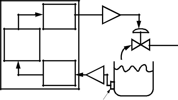
25.4.2 Water Tank Level Control
Problem: The system in Figure 25.19 will control the height of the water in a tank. The input from the pressure transducer, Vp, will vary between 0V (empty tank) and 5V (full tank). A voltage output, Vo, will position a valve to change the tank fill rate. Vo varies between 0V (no water flow) and 5V (maximum flow). The system will always be on: the emergency stop is connected electrically. The desired height of a tank is specified by another voltage, Vd. The output voltage is calculated using Vo = 0.5 (Vd - Vp). If the output voltage is greater than 5V is will be made 5V, and below 0V is will be made 0V.
Digital |
|
Amp |
to Analog |
|
|
|
|
|
Converter |
|
|
PLC |
|
Water |
Running |
|
Supply |
Control |
|
|
Program |
|
|
Analog |
|
|
to Digital |
Amp |
Water Tank |
Converter |
|
|
|
|
|
|
pressure |
|
|
transducer |
|
Figure 25.19 Water Tank Level Controller |
|
|
plc pid - 25.18
SOLUTION Analog Input: Select a 12 bit 1771-IFE card and use the 0V to 5V range on channel 1 with double ended inputs.
R = 2N = 4096
Analog Output: Select a 12 bit 1771-OFE card and use the 0V to 5V range on channel 1.
R = 2N = 4096
Cards: I:000 - Analog Input
I:001 - Analog Output
Memory: N7:80 - Vd

plc pid - 25.19
S2:1/15 - first scan
BT9:0/EN BT9:1/EN
MOV
Source 0000 0000 0000 0001
Dest N7:0
MOV
Source 0000 0101 0000 0000
Dest N7:2
MOV
Source 1000 0000 0000 0000
Dest N7:64
BTW
Rack: 0
Group: 0
Module: 0
BT Array: BT9:0
Data File: N7:0
Length: 37
Continuous: no
BTR
Rack: 0
Group: 0
Module: 0
BT Array: BT9:1
Data File: N7:37
Length: 20
Continuous: no
Figure 25.20 A Water Tank Level Control Program