

50. Characteristics of ideal pump. Degree of reaction
Equation (12.8) is inconvenient for calculations as it does not contain the rate of discharge Q. Therefore let us rewrite it to express the head Hta> as a function of the discharge Q and impeller radius.
From the velocity triangle for the impeller exit (Fig. 133).
![]()
where v2r = projection of absolute exit velocity on radius, i. e., the radial component of vector v2.
The rate of discharge through the impeller can be expressed in terms of the radial component v2r and impeller radius as follows:
![]()
where b2 = width of vane slot at exit (see Fig. 132). Hence
![]()
Substitution of this expression into Eq. (12.9) yields
![]()
Substituting the obtained expression (12.11) for the tangential velocity component
v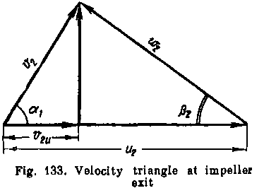
 2u
in
Eq. (12.8), we obtain another
form of the basic ideal pump
equation:
2u
in
Eq. (12.8), we obtain another
form of the basic ideal pump
equation:
![]()
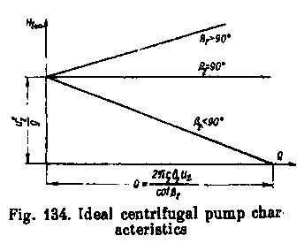
This equation can be used to plot the theoretical characteristics of an idealised centrifugal pump, i. e., a curve of the head generatedby the pump as a function of the discharge for a constant speed of rotation. It is evident from Eq. (12.12) that the characteristic curve of such a pump is a straight line the inclination of which depends on the value of the vane angle p2.The following three cases are possible.
1.
Angle p2
< 90°. In this case cot β2
is positive and the head
![]() decreases with the
discharge increasing.
decreases with the
discharge increasing.
2. Angle p2
= 90°, cot β
2 = 0, and Htto
does not depend on the discharge and
is equal to
![]() .
.
3. Angle P2>90°, cot β 2 is negative and the head Him increases with the discharge.
These three theoretical pump characteristics are shown in Fig. 134. The corresponding vane shapes and velocity parallelograms for the same values of u2 and y2r are presented in Fig. 135a, b, с
It thus follows that the optimum head is produced by a forward-curved vane, when β 2 > 90° and the head is highest. In practice, however, the efficiency of such a pump is low, and the performance of backward-curved vanes at β 2 < 90° is found to be preferable. Backward-curved vanes are in fact more commonly used, the vane angle usually being about 30°. Radial vanes (p2 = 90°) are also employed, but the result is lower efficiency and the considerations to be guided by are usually those of size, strength, etc.
In
order to understand why pump efficiency falls with t£e angle β
2
increasing we must examine the components of the head
![]() and
the way in which the relation between them changes with β
2.
and
the way in which the relation between them changes with β
2.
The
head
![]() ,
or what is the same thing, the total increase in the
specific energy of a fluid in an impeller, comprises the increase in
the specific energy of pressure and the specific kinetic energy,
i.e.,
,
or what is the same thing, the total increase in the
specific energy of a fluid in an impeller, comprises the increase in
the specific energy of pressure and the specific kinetic energy,
i.e.,
![]()

or, introducing another notation,
![]()
Expressing the velocities vi and v2 in terms of their radial and tangential components, we have
![]()
Assuming the intake and exit areas of the impeller to be approximately equal, we can consider that vlr = v2r. Furthermore, as pointed out before, there is usually no prerotation of the fluid at the impeller intake, and vla = 0. Consequently, instead of the foregoing we have
![]()
Taking this expression into account, we can now find from Eq. (12.13) the so-called degree of reaction of the pump, which is the ratio of the head imparted to the fluid by the pressure increase to the total head:
![]()
Using Eq. (12.8), the latter expression can be rewritten as follows
![]()
whence finally, after substituting for v2u from Eq. (12.9),
![]()
It will be observed from this expression that the greater v2r/v2 and the smaller angle |32, the greater the portion of the head Ht<J} that is produced by the pressure increase, i.e., the higher the degree of reaction of the pump. With angle (J2 increasing the portion of the head #/00 representing the increase in the kinetic energy becomes greater. The kinetic energy, in turn, is associated with higher exit velocity of the fluid from the impeller, which results in considerable energy losses and lower pump efficiency. That is why it is not expedient to use vanes with large values of |J2, i.e., forward-bent vanes.
It follows from Eq. (12.15) that for radial vanes (p2 = 90°) the degree of reaction is 1/2, and at ($2 < 90° it is more than 1/2 but less than unity.
The way in which the velocity parallelograms change and the increase in the absolute exit velocity v2 with angle P2 increasing are illustrated in Fig. 135.