

57. Cavitation conditions for centrifugal pumps (according to s.S. Rudnev)
Any pump, whether centrifugal or of other design, can operate normally only if the absolute pressure in the suction pipe is not too low. Otherwise cavitation develops at the intake, or rather at the entrance of the liquid to the vane passages, where the absolute pressure is lowest (see Sec. 21).
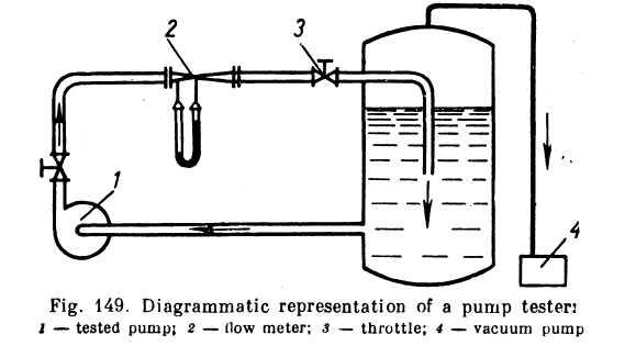
Cavitation results in intermittent stream, due to the evolution of vapour and dissolved gases; a characteristic noise produced by hydraulic shocks in the condensation of vapour bubbles appears; and the delivery, head and efficiency of the pump fall. The intensity of these phenomena increases with the absolute pressure at the impeller eye decreasing, which is demonstrated graphically by the so-called cavitation characteristic curves of a centrifugal pump. The curves are plotted for the head, capacity and efficiency of the pump as a function of the absolute pressure of the liquid at intake. They are usually obtained in special tests in which the speed of rotation and the discharge (by throttling) are maintained constant;
i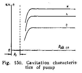 n
the course of a test the absolute pressure at the impeller
intake is gradually reduced (for instance, by evacuating air from
the reservoir).* The setup for experimentally determining the
cavitation characteristics of a pump is presented schematically
in Fig. 149. The head, capacity and efficiency of the pump are at
first constant (Fig. 150); when the pressure drops sufficiently, the
characteristic noise appears and the respective values begin to fall
rapidly as a result of cavitation at the intake.
n
the course of a test the absolute pressure at the impeller
intake is gradually reduced (for instance, by evacuating air from
the reservoir).* The setup for experimentally determining the
cavitation characteristics of a pump is presented schematically
in Fig. 149. The head, capacity and efficiency of the pump are at
first constant (Fig. 150); when the pressure drops sufficiently, the
characteristic noise appears and the respective values begin to fall
rapidly as a result of cavitation at the intake.
The higher the speed of rotation and discharge the higher the velocity of the liquid and the lower the absolute pressure at intake, which facilitates cavitation. Thus, cavitation imposes limitations on the rate of discharge and speed of rotation of a pump.
In the following, liquid flow at impeller intake is investigated, impeller eye diameter is determined from cavitation conditions and a cavitation criterion is developed by the method of Soviet scientist S.S. Rudnev.
Let the velocity of a liquid at the intake of a pump be vin, and the absolute pressure pin; then the specific energy of the liquid at the intake will be
![]()
When the liquid approaches the impeller vanes the pressure drops further in proportion to the velocity head as computed according to the relative entrance velocity; there is no cavitation as long as the absolute pressure of the liquid is greater than the saturation vapour pressure for the given temperature.
Thus, the condition under which no cavitation occurs can be expressed by the following inequality:
![]()
where v1 = absolute velocity of approach of liquid to vane, approximately equal to the intake velocity v0 at the impeller eye;
ω1 = relative velocity at the same place;
h1 = saturation vapour pressure divided by γ, i.e,
![]()
* Cavitation characteristics may also be obtained for a constant throttle position, i.e., for a reduced delivery due to cavitation.
λ = factor depending on vanp geometry and flow conditions;
![]() =
pressure drop as liquid reaches vane.
=
pressure drop as liquid reaches vane.
The foregoing inequality can also be written down as follows:
![]()
The left-hand side of the inequality represents the actual specific energy of the fluid at the pump intake, which in the limit may become equal to the right-hand side. The equation will then correspond to the beginning of cavitation, which is why we shall call the difference Hin - ht critical when it is equal to the right-hand side:
![]()
Since,
as a rule,
![]() ,
,
![]()
Thus, (Hin - ht)cr should be kept as low as possible, for the smaller this critical value the less liable is cavitation to develop. It will be observed from the foregoing that (Hin - ht)cr depends on the velocities ux and u, which, in turn, depend, for given Q and n, on the diameter Dly approximately equal to. Do (see Fig. 132). The problem, then, is of choosing an impeller eye diameter to ensure the lowest possible value of (Hin - ht)cr For this, express the velocities y, and w, in terms of £>, and investigate for the minimum. We have
![]()
Differentiating with respect to D1 and equating the derivative to zero, we obtain
![]()
whence
![]()
And finally we obtain the following expression for the optimum diameter:
![]() (12.43)
(12.43)
where the factor k0 may vary from 4.3 to 4.5, depending on X.
For actual solutions, in view of the possibility of overloading, the upper limit should be taken.
From the expression for the optimum diameter, determine the minimum val-lue of Win - ht)cr:
![]()
or, after substituting, rearranging and solving,
![]()
where s = factor determined by λ; at λ = 0.25, s ≈ 0.02.
Pump tests indicate that this value of s can be used in calculating impellers of conventional geometry. For impellers of special design, for example with increased width b1 , the value of s is reduced to 0.012-0.013.
If the impeller eye diameter D1 is optimal no-cavitation conditions will be given by the inequality:
![]() (12.44)
(12.44)
The factor s thus offers a criterion of cavitation in a pump which can be used to verify computations and to determine the maximum permissible rpm of a pump for a given Q and Hin or the minimum permissible absolute pressure at intake.
The latter, it follows from the previously accepted notation and the foregoing inequality, is determined from the condition
![]()
The velocity head in the parantheses is often neglected, as this increases the reliability of a pump as far as cavitation is concerned; the difference pin - pt is called the cavitation pressure allowance.
Often another quantity, called the cavitation parameter, is used
![]()
wbere H = head delivered by the pump.
The cavitation parameter is readily associated with the specific speed. From the foregoing,
![]()
where, at s = 0.02,
![]()
In aircraft and liquid-propellant rocket systems the following measures are taken to prevent cavitation in pumps:
(a) Gas pressure is increased in the tank from which the liquid is pumped. As this calls for heavier tanks the pressure is usually not more than about three atmospheres.
A booster pump is installed at the beginning of the suction pipeline. This is possible only when power can be supplied to drive the pump (say, electricity).
An axial or helical wheel is mounted immediately before the impeller on the same shaft to increase pressure and impart whirl to the flow. The latter results in a reduction of the relative velocity xvx and improves operating conditions of the impeller. The auxiliary runner can completely prevent cavitation from developing at the impeller, but as its speed of rotation n and rate of discharge Q are the same as those of the impeller, cavitation can develop on the auxi liary runner itself. The best device, therefore, would be one in which the rotational speed of the auxiliary runner is less than that of the impeller.