9. Fluid pressure on cylindrical and spherical surfaces. Buoyancy and floatation
Problems involving the pressure of fluids on surfaces of arbitrary shape are rather difficult as they require the determination of three; components of the total force and three moments. Fortunately, such cases are not so frequently encountered in practice. Usually we have to deal with cylindrical or spherical surfaces having a vertical plane of symjnetry. In this case the pressure can be reduced : to a resultant in the plape of symmetry.
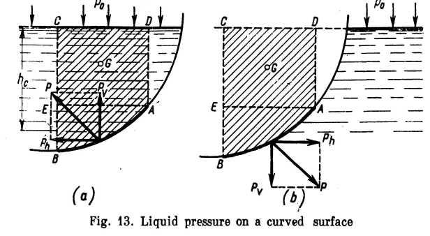
Consider a curved surface AB whose generator is perpendicular to the page (Fig. 13). Two cases are possible: (a) the liquid lies above the surface and (b) the liquid lies below the surface.
Case (a): consider the liquid volume ABCD, where AB is the curved surface, ВС and AD are vertical surfaces, and CD is the free surface of the liquid. Let us investigate the equilibrium conditions in the vertical and horizontal directions. If the liquid exerts a thrust P on surface AB, the latter can be said to be exerting an equal and oppositely directed force on the liquid. In Fig. 13 this reaction force is shown together with its horizontal and vertical components Ph and PD.
The condition for the vertical equilibrium of the volume A BCD is
![]() , (2.8)
, (2.8)
where p0 = pressure acting on the free surface;
Sh = area of the horizontal projection of AB;
G = weight of the liquid in the volume under consideration.
In writing the condition for horizontal equilibrium account is
taken of the fact that the thrust of the liquid on areas EC and AD is
balanced and only the pressure on area BE (which is the vertical
projection Sv of surface AB) remains:
![]() .
(2.9)
.
(2.9)
Equations (2.8) and (2.9) give the vertical and horizontal components of the total pressure P, whence
![]() (2.10)
(2.10)
Case (b) (Fig. 13b): the hydrostatic pressure has the same magnitude at all points of AB, as in case (a), but it is oppositely directed. The forces Pv and Ph are given by the Eqs (2.8) and (2.9) with the signs reversed. As in case (a), G is the weight of the liquid corresponding to the volume ABCD (which, of course, is actually empty).
The centre of pressure of a curved area can be readily located if the magnitude and direction of forces PD and Ph are known, i. e., if the centre of pressure of the vertical projection of the area and the centre of gravity of the volume ABCD are known. The problem is simplified when the curved surface is circular. In this case the resultant force intersects with the centre line of the surface, which follows from the fact that any elementary pressure dP is normal to the surface, i. e., it is directed along the radius.
This method of determining the pressure on a cylindrical area can be used for spherical surfaces. The resultant passes though the centre of the area in the vertical plane of symmetry.
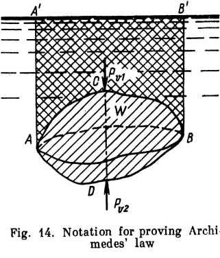
The method of finding the vertical component of the pressure force on a curved area can also be used to prove the famous Archimedes' law.
Let any body of volume W be immersed in a liquid (Fig. 14). A vertical generator moving around the body describes a curve which divides the body into two parts ACB and ADB. The vertical component PVl of the gauge pressure acting on the part of the surface above АВ is directed downward and is equal to the weight of the liquid in the volume AA'B'BCA. The vertical component PV2 of the pressure acting on the lower portion of the body is directed upward and is equal to the weight of the liquid contained in the volume AA'B’ BDA.
It follows, then, that the vertical resultant of the pressure exerted by the liquid on the body is directed upward and is equal to the weight of the liquid contained in the difference between the two volumes, i. e., in the volume of the body:
![]() .
.
This is known as Archimedes’ law, which states: A body immersed in a fluid loses as much of its weight as the weight of the fluid dis-ulaced by it. The law, of course, holds good for partially immersed bodies as well. The force Pb is called the buoyancy force and its point }f application, which is the centre of gravity of the displaced liquid, is called the centre of buoyancy.
Depending on the ratio of the weight G of a body and the buoyancy force Pbi three cases are possible: (i) G > Pby and the body sinks; ii) G < Pb, and the body rises; (iii) G = Pb, and the body floats.
For the stability of a floating body it is necessary, besides the equality of forces G and Pby that the total moment be zero. The later condition is fulfilled when the centre of gravity and the centre of buoyancy lie on the same vertical. The stability of floating bodies, lowever, will not be discussed in this book.
Example 1. Many aircraft hydraulic systems include a gas-loaded accumu-ator for energy storage. Stripped of the unessentials, an accumulator consists of a cylinder with a piston on one side of which there is air under pressure p ind on the other side the hydraulic fluid, which is injected by pump (Fig. 15).* The energy is stored by the fluid pushing the piston to the left and compressing he air volume W. The stored energy is delivered by the expanding air.
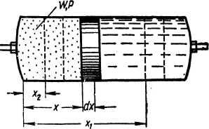
The following assumptions are made: (i) the compression and expansion of the air is an isothermal process; (ii) the air volume is proportional to the displacement x of the piston; (iii) the piston moves without friction.
Solution.
The
elementary work done by the accumulator is
![]() ,
,
where S = area of the piston and, as assumed,
![]() and
and
![]()
Hence,
![]()
* Another type is a spherical accumulator with an elastic diaphragm sep-rating the fluid from the compressed air (see Fig. 18).
The stored energy is determined by integration:
whence, substituting the numerical values,
![]()
Example 2. In Fig. 16 is shown schematically a hydraulic machine which can operate either as a press or as a jack. When working as a jack, 1 is the load to be lifted; when working as a press, 1 is a rigid support attached to the foundation by vertical columns 8 (shown by broken lines) and body 2 is the pressed object.
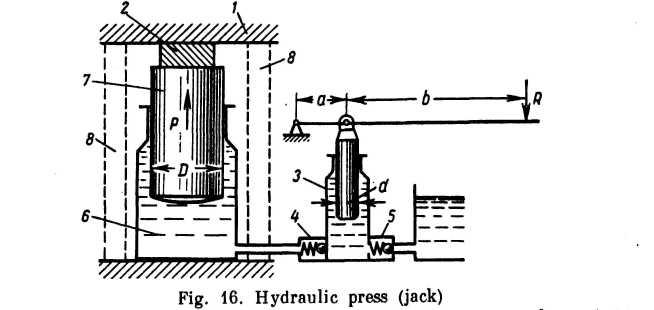
The hand-driven pump 3, where 5 is the intake, or suction, valve and 4 is the discharge, or pressure, valve, is used to supply pressure into cylinder 6, thereby developing an upward thrust P on the lifting ram 7.
Determine force P if R = 20 kg, nib = 1/9 and Did = 10.
Solution.
![]()
Example 3. The hydraulic pressure intensifier in Fig. 17 is used to increase the pressure px supplied by a pump or accumulator. The pressure рг is supplied into a cylinder 1 in which moves a hollow ram 2 of weight G and diameter D. The hollow ram slides along a-fixed ram 3 of diameter d in which is bored an outlet for the fluid at the increased pressure pt.
Determine the pressure pt if G = 300 kg, D = 125 mm, px = 100 kg/cm' and d = 50 mm. Neglect friction.

Solution. From the equilibrium conditions for the hollow ram 2 we have
![]()
whence
![]()
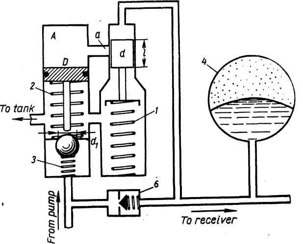
Example 4. A component of aircraft hydraulic systems is an automatic relief valve (Fig. 18) which works in the following manner. When the fluid in the system is idling the pump charges a hydraulic accumulator 4 until a pressure pmax is reached at which piston d moves down, letting the fluid into space A via pipe a. The pressure pmax drives piston D down; the piston rod opens а ball valve connecting the pressure^ pipe of the pump with the tank. The pump* delivers the fluid back into the tank as long as the pressure in the system remains above pmin, at which piston d moves up and the fluid in space A drains into the tank. When this happens spring 2 pushes piston D up, the ball valve closes and the pump supplies pressure to the receiver.
Calculate the characteristics of springs 1 and 2 if pmax == 140 atm, pmin = 80 atm, d=8 mm, J = 16 mm, D «. 10 mm, a « 2 mm and d} = 6 mm. Solution. Determine the maximum and minimum loads on spring 1
![]()
![]()
The deflection of the spring is
![]()
Now calculate the stiffness of spring 1:
![]()
In order to open the ball valve, the thrust on the piston should be sufficient to overcome the resistance of spring 2, the friction of the piston packing, the pressure acting on the ball valve and the thrust of spring 3. Assuming the frictional force to be 0.1 of the pressure force and the thrust of spring 3Q = 30 kg, we obtain the following equation for determining the maximum stress Fmax of spring 2:
![]()
whence
![]()
But, on the other hand, the thrust of spring 2 should be sufficient to reverse the motion of piston D against the friction of the packing of the unloaded piston. Assuming the frictional force to be 10 kg we obtain