

- •About the Authors
- •Dedication
- •Authors’ Acknowledgments
- •Table of Contents
- •Introduction
- •What’s Not (And What Is) in This Book
- •Mac attack!
- •Who Do We Think You Are?
- •How This Book Is Organized
- •Part I: AutoCAD 101
- •Part II: Let There Be Lines
- •Part III: If Drawings Could Talk
- •Part IV: Advancing with AutoCAD
- •Part V: On a 3D Spree
- •Part VI: The Part of Tens
- •But wait . . . there’s more!
- •Icons Used in This Book
- •A Few Conventions — Just in Case
- •Commanding from the keyboard
- •Tying things up with the Ribbon
- •Where to Go from Here
- •Why AutoCAD?
- •The Importance of Being DWG
- •Seeing the LT
- •Checking System Requirements
- •Suddenly, It’s 2013!
- •AutoCAD Does Windows (And Office)
- •And They’re Off: AutoCAD’s Opening Screens
- •Running with Ribbons
- •Getting with the Program
- •Looking for Mr. Status Bar
- •Let your fingers do the talking: The command window
- •The key(board) to AutoCAD success
- •Keeping tabs on palettes
- •Down the main stretch: The drawing area
- •Fun with F1
- •A Simple Setup
- •Drawing a (Base) Plate
- •Drawing rectangles on the right layers
- •Circling your plate
- •Nuts to you
- •Getting a Closer Look with Zoom and Pan
- •Modifying to Make It Merrier
- •Hip-hip-array!
- •Stretching out
- •Crossing your hatches
- •Following the Plot
- •A Setup Roadmap
- •Choosing your units
- •Weighing up your scales
- •Thinking annotatively
- •Thinking about paper
- •Defending your border
- •A Template for Success
- •Making the Most of Model Space
- •Setting your units
- •Making the drawing area snap-py (and grid-dy)
- •Setting linetype and dimension scales
- •Entering drawing properties
- •Making Templates Your Own
- •Setting Up a Layout in Paper Space
- •Will that be tabs or buttons?
- •View layouts Quick(View)ly
- •Creating a layout
- •Copying and changing layouts
- •Lost in paper space
- •Spaced out
- •A view(port) for drawing in
- •About Paper Space Layouts and Plotting
- •Managing Your Properties
- •Layer one on me!
- •Accumulating properties
- •Creating new layers
- •Manipulating layers
- •Using Named Objects
- •Using AutoCAD DesignCenter
- •Copying layers between drawings
- •Controlling Your Precision
- •Keyboard capers: Coordinate input
- •Understanding AutoCAD’s coordinate systems
- •Grab an object and make it snappy
- •Other Practical Precision Procedures
- •Introducing the AutoCAD Drawing Commands
- •The Straight and Narrow: Lines, Polylines, and Polygons
- •Toeing the line
- •Connecting the lines with polyline
- •Squaring off with rectangles
- •Choosing your sides with polygon
- •(Throwing) Curves
- •Going full circle
- •Arc-y-ology
- •Solar ellipses
- •Splines: The sketchy, sinuous curves
- •Donuts: The circles with a difference
- •Revision clouds on the horizon
- •Scoring Points
- •Commanding and Selecting
- •Command-first editing
- •Selection-first editing
- •Direct object manipulation
- •Choosing an editing style
- •Grab It
- •One-by-one selection
- •Selection boxes left and right
- •Perfecting Selecting
- •AutoCAD Groupies
- •Object Selection: Now You See It . . .
- •Get a Grip
- •About grips
- •A gripping example
- •Move it!
- •Copy, or a kinder, gentler Move
- •A warm-up stretch
- •Your AutoCAD Toolkit
- •The Big Three: Move, Copy, and Stretch
- •Base points and displacements
- •Move
- •Copy
- •Copy between drawings
- •Stretch
- •More Manipulations
- •Mirror
- •Rotate
- •Scale
- •Array
- •Offset
- •Slicing, Dicing, and Splicing
- •Trim and Extend
- •Break
- •Fillet and Chamfer and Blend
- •Join
- •When Editing Goes Bad
- •Zoom and Pan with Glass and Hand
- •The wheel deal
- •Navigating your drawing
- •Controlling your cube
- •Time to zoom
- •A View by Any Other Name . . .
- •Looking Around in Layout Land
- •Degenerating and Regenerating
- •Getting Ready to Write
- •Simply stylish text
- •Taking your text to new heights
- •One line or two?
- •Your text will be justified
- •Using the Same Old Line
- •Turning On Your Annotative Objects
- •Saying More in Multiline Text
- •Making it with Mtext
- •It slices; it dices . . .
- •Doing a number on your Mtext lists
- •Line up in columns — now!
- •Modifying Mtext
- •Gather Round the Tables
- •Tables have style, too
- •Creating and editing tables
- •Take Me to Your Leader
- •Electing a leader
- •Multi options for multileaders
- •How Do You Measure Up?
- •A Field Guide to Dimensions
- •The lazy drafter jumps over to the quick dimension commands
- •Dimension associativity
- •Where, oh where, do my dimensions go?
- •The Latest Styles in Dimensioning
- •Creating and managing dimension styles
- •Let’s get stylish!
- •Adjusting style settings
- •Size Matters
- •Details at other scales
- •Editing Dimensions
- •Editing dimension geometry
- •Editing dimension text
- •Controlling and editing dimension associativity
- •Batten Down the Hatches!
- •Don’t Count Your Hatches. . .
- •Size Matters!
- •We can do this the hard way. . .
- •. . . or we can do this the easy way
- •Annotative versus non-annotative
- •Pushing the Boundary (Of) Hatch
- •Your hatching has no style!
- •Hatch from scratch
- •Editing Hatch Objects
- •You Say Printing, We Say Plotting
- •The Plot Quickens
- •Plotting success in 16 steps
- •Get with the system
- •Configure it out
- •Preview one, two
- •Instead of fit, scale it
- •Plotting the Layout of the Land
- •Plotting Lineweights and Colors
- •Plotting with style
- •Plotting through thick and thin
- •Plotting in color
- •It’s a (Page) Setup!
- •Continuing the Plot Dialog
- •The Plot Sickens
- •Rocking with Blocks
- •Creating Block Definitions
- •Inserting Blocks
- •Attributes: Fill-in-the-Blank Blocks
- •Creating attribute definitions
- •Defining blocks that contain attribute definitions
- •Inserting blocks that contain attribute definitions
- •Edit attribute values
- •Extracting data
- •Exploding Blocks
- •Purging Unused Block Definitions
- •Arraying Associatively
- •Comparing the old and new ARRAY commands
- •Hip, hip, array!
- •Associatively editing
- •Going External
- •Becoming attached to your xrefs
- •Layer-palooza
- •Creating and editing an external reference file
- •Forging an xref path
- •Managing xrefs
- •Blocks, Xrefs, and Drawing Organization
- •Mastering the Raster
- •Attaching a raster image
- •Maintaining your image
- •Theme and Variations: Dynamic Blocks
- •Lights! Parameters!! Actions!!!
- •Manipulating dynamic blocks
- •Maintaining Design Intent
- •Defining terms
- •Forget about drawing with precision!
- •Constrain yourself
- •Understanding Geometric Constraints
- •Applying a little more constraint
- •AutoConstrain yourself!
- •Understanding Dimensional Constraints
- •Practice a little constraint
- •Making your drawing even smarter
- •Using the Parameters Manager
- •Dimensions or constraints — have it both ways!
- •The Internet and AutoCAD: An Overview
- •You send me
- •Send it with eTransmit
- •Rapid eTransmit
- •Bad reception?
- •Help from the Reference Manager
- •Design Web Format — Not Just for the Web
- •All about DWF and DWFx
- •Autodesk Design Review 2013
- •The Drawing Protection Racket
- •Autodesk Weather Forecast: Increasing Cloud
- •Working Solidly in the Cloud
- •Free AutoCAD!
- •Going once, going twice, going 123D
- •Your head planted firmly in the cloud
- •The pros
- •The cons
- •Cloudy with a shower of DWGs
- •AutoCAD 2013 cloud connectivity
- •Tomorrow’s Forecast
- •Understanding 3D Digital Models
- •Tools of the Trade
- •Warp speed ahead
- •Entering the third dimension
- •Untying the Ribbon and opening some palettes
- •Modeling from Above
- •Using 3D coordinate input
- •Using point filters
- •Object snaps and object snap tracking
- •Changing Planes
- •Displaying the UCS icon
- •Adjusting the UCS
- •Navigating the 3D Waters
- •Orbit à go-go
- •Taking a spin around the cube
- •Grabbing the SteeringWheels
- •Visualizing 3D Objects
- •Getting Your 3D Bearings
- •Creating a better 3D template
- •Seeing the world from new viewpoints
- •From Drawing to Modeling in 3D
- •Drawing basic 3D objects
- •Gaining a solid foundation
- •Drawing solid primitives
- •Adding the Third Dimension to 2D Objects
- •Creating 3D objects from 2D drawings
- •Modifying 3D Objects
- •Selecting subobjects
- •Working with gizmos
- •More 3D variants of 2D commands
- •Editing solids
- •Get the 2D Out of Here!
- •A different point of view
- •But wait! There’s more!
- •But wait! There’s less!
- •Do You See What I See?
- •Visualizing the Digital World
- •Adding Lighting
- •Default lighting
- •User-defined lights
- •Sunlight
- •Creating and Applying Materials
- •Defining a Background
- •Rendering a 3D Model
- •Autodesk Feedback Community
- •Autodesk Discussion Groups
- •Autodesk’s Own Bloggers
- •Autodesk University
- •The Autodesk Channel on YouTube
- •The World Wide (CAD) Web
- •Your Local ATC
- •Your Local User Group
- •AUGI
- •Books
- •Price
- •3D Abilities
- •Customization Options
- •Network Licensing
- •Express Tools
- •Parametrics
- •Standards Checking
- •Data Extraction
- •MLINE versus DLINE
- •Profiles
- •Reference Manager
- •And The Good News Is . . .
- •APERTURE
- •DIMASSOC
- •MENUBAR
- •MIRRTEXT
- •OSNAPZ
- •PICKBOX
- •REMEMBERFOLDERS
- •ROLLOVERTIPS
- •TOOLTIPS
- •VISRETAIN
- •And the Bonus Round
- •Index
444 Part IV: Advancing with AutoCAD
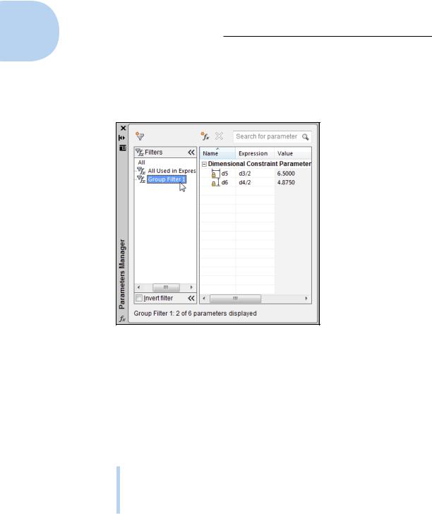
of the palette to open the Filters pane. Click the funnel icon in the toolbar to create a new filter group, and then simply drag and drop parameters into the group. Figure 19-14 shows the two constraints added in Steps 5 and 6 (of the preceding step list) dragged into a new group filter.
Figure 19-14: Filter your parameters to keep them organized.
Dimensions or constraints — have it both ways!
After all that hard work adding dimensional constraints to your drawings, it would be a downright shame to have to go back and apply regular dimensions, wouldn’t it? Well, you don’t have to. You can make dimensional constraints look and behave like regular dimensions. You can go the other way, too, and make your regular dimensions act like dimensional constraints.
Dimensional constraints are available in two flavors:
Dynamic constraints: The default form. Dynamic constraints appear gray with a padlock icon next to them in the drawing area. You can make them appear and disappear by clicking Show All in the Dimensional panel. They don’t plot, and they resize as you zoom in and out of the drawing, so they’re always legible.
www.it-ebooks.info
Chapter 19: Call the Parametrics! 445
Annotational constraints: This form is controlled as an object property, so you have to set it in the Properties palette. Annotational constraints do plot, don’t resize as you zoom in and out, and don’t disappear as you toggle the Show All button on and off. Annotational constraints conform to dimension style settings.
The dimension name format of annotational constraints can be set to Name, Value, or Name and Expression, just like dynamic constraints (refer to Figure 19-10 for another look at the Constraint Settings dialog box). If you’re going to plot your drawing with annotational constraints, remember to reset the format so it doesn’t show the dimension name or the expression.
Here’s how to turn dynamic dimensional constraints into annotational constraints.
1.Open a drawing that contains some geometry with dimensional constraints.
You can also start a new drawing, draw some simple geometry, and add a dimensional constraint to two.
2.Select a dynamic constraint, right-click, and choose Properties.
The Properties palette opens with the object properties of the selected dimensional constraint listed in table form.
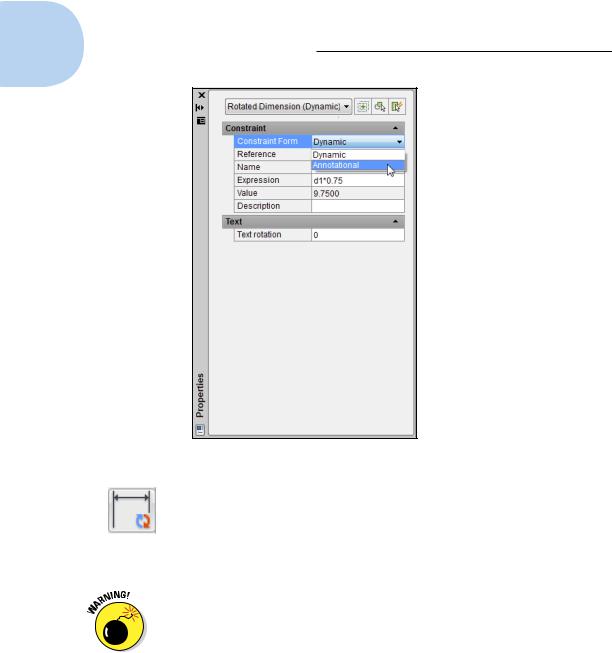
3.Click in the Constraint Form field, and in the drop-down list, change Dynamic to Annotational (see Figure 19-15).
The dynamic constraint becomes annotational, and takes on the appearance of the current dimension style. If you change the dimension style in the Properties palette, the annotational constraint updates to the new dimension style format.
You can go the other way, too, from regular dimension objects to dimensional constraints.
4.Add a linear, radius, diameter, aligned, or angular dimension (that is, a regular dimension, not a dimensional parameter) to your drawing geometry.
Nearly every type of dimension object has a parametric analog; the exceptions are arc length, jogged radius, jogged linear, and ordinate dimensions.
www.it-ebooks.info
446 Part IV: Advancing with AutoCAD
Figure 19-15: Turning dynamic constraints into annotational ones.
5.Click Convert in the Dimensional panel, select one of the dimension types in Step 4, and press Enter.
The Dimensional Constraint text box displays as soon as you click an associative dimension, and the dimension becomes a dynamic constraint as soon as you press Enter.
The only clue that a dimension is an annotational constraint rather than a regular old associative dimension is the padlock icon that appears next to the dimension value. You can turn off the display of the padlock in the Constraint Settings dialog box, but we recommend that you leave it on. It
doesn’t plot anyway, and you might decide to delete the dimension without realizing that’s it’s controlling your object geometry.
Annotational dimensions can also be annotative so that they size themselves automatically to the drawing scale. We cover annotative dimensions in Chapter 14. Annotational and annotative dimensions are also associative, so you can have annotative annotational associative dimensions. Try saying that after a few drinks.
www.it-ebooks.info
Chapter 19: Call the Parametrics! 447
In this chapter, we present the two varieties of parametric constraints separately, but you’ll get the most mileage from this feature when you incorporate both geometric and dimensional constraints with all those other precision techniques that we tell you about in Chapter 7. In fact, if you start a drawing by using Snap, Ortho, Osnap, and other precision techniques before you start adding dimensional and parametric constraints, you’ll be well on the way to creating a library of intelligent drawings that maintain your design intent.
Geometric and dimensional constraints can be equivalent. For example, a 90-degree angle dimensional constraint is equal to a perpendicular geometric constraint, and AutoCAD won’t let you apply both.
All the examples in this chapter involve a single drawing view. Geometric constraints actually apply “to infinity,” and so you can synchronize objects in one orthographic view with those in another. For example, coincident and collinear constraints can link objects in the front view with their equivalents in the top and right-side views, and liberal use of the Equal constraint means that you should never have to measure or dimension anything twice, you should only ever need minimal construction geometry, any changes in one view reflect through to the others, and your views always remain orthogonally aligned.
www.it-ebooks.info

448 Part IV: Advancing with AutoCAD
www.it-ebooks.info