

- •About the Authors
- •Dedication
- •Authors’ Acknowledgments
- •Table of Contents
- •Introduction
- •What’s Not (And What Is) in This Book
- •Mac attack!
- •Who Do We Think You Are?
- •How This Book Is Organized
- •Part I: AutoCAD 101
- •Part II: Let There Be Lines
- •Part III: If Drawings Could Talk
- •Part IV: Advancing with AutoCAD
- •Part V: On a 3D Spree
- •Part VI: The Part of Tens
- •But wait . . . there’s more!
- •Icons Used in This Book
- •A Few Conventions — Just in Case
- •Commanding from the keyboard
- •Tying things up with the Ribbon
- •Where to Go from Here
- •Why AutoCAD?
- •The Importance of Being DWG
- •Seeing the LT
- •Checking System Requirements
- •Suddenly, It’s 2013!
- •AutoCAD Does Windows (And Office)
- •And They’re Off: AutoCAD’s Opening Screens
- •Running with Ribbons
- •Getting with the Program
- •Looking for Mr. Status Bar
- •Let your fingers do the talking: The command window
- •The key(board) to AutoCAD success
- •Keeping tabs on palettes
- •Down the main stretch: The drawing area
- •Fun with F1
- •A Simple Setup
- •Drawing a (Base) Plate
- •Drawing rectangles on the right layers
- •Circling your plate
- •Nuts to you
- •Getting a Closer Look with Zoom and Pan
- •Modifying to Make It Merrier
- •Hip-hip-array!
- •Stretching out
- •Crossing your hatches
- •Following the Plot
- •A Setup Roadmap
- •Choosing your units
- •Weighing up your scales
- •Thinking annotatively
- •Thinking about paper
- •Defending your border
- •A Template for Success
- •Making the Most of Model Space
- •Setting your units
- •Making the drawing area snap-py (and grid-dy)
- •Setting linetype and dimension scales
- •Entering drawing properties
- •Making Templates Your Own
- •Setting Up a Layout in Paper Space
- •Will that be tabs or buttons?
- •View layouts Quick(View)ly
- •Creating a layout
- •Copying and changing layouts
- •Lost in paper space
- •Spaced out
- •A view(port) for drawing in
- •About Paper Space Layouts and Plotting
- •Managing Your Properties
- •Layer one on me!
- •Accumulating properties
- •Creating new layers
- •Manipulating layers
- •Using Named Objects
- •Using AutoCAD DesignCenter
- •Copying layers between drawings
- •Controlling Your Precision
- •Keyboard capers: Coordinate input
- •Understanding AutoCAD’s coordinate systems
- •Grab an object and make it snappy
- •Other Practical Precision Procedures
- •Introducing the AutoCAD Drawing Commands
- •The Straight and Narrow: Lines, Polylines, and Polygons
- •Toeing the line
- •Connecting the lines with polyline
- •Squaring off with rectangles
- •Choosing your sides with polygon
- •(Throwing) Curves
- •Going full circle
- •Arc-y-ology
- •Solar ellipses
- •Splines: The sketchy, sinuous curves
- •Donuts: The circles with a difference
- •Revision clouds on the horizon
- •Scoring Points
- •Commanding and Selecting
- •Command-first editing
- •Selection-first editing
- •Direct object manipulation
- •Choosing an editing style
- •Grab It
- •One-by-one selection
- •Selection boxes left and right
- •Perfecting Selecting
- •AutoCAD Groupies
- •Object Selection: Now You See It . . .
- •Get a Grip
- •About grips
- •A gripping example
- •Move it!
- •Copy, or a kinder, gentler Move
- •A warm-up stretch
- •Your AutoCAD Toolkit
- •The Big Three: Move, Copy, and Stretch
- •Base points and displacements
- •Move
- •Copy
- •Copy between drawings
- •Stretch
- •More Manipulations
- •Mirror
- •Rotate
- •Scale
- •Array
- •Offset
- •Slicing, Dicing, and Splicing
- •Trim and Extend
- •Break
- •Fillet and Chamfer and Blend
- •Join
- •When Editing Goes Bad
- •Zoom and Pan with Glass and Hand
- •The wheel deal
- •Navigating your drawing
- •Controlling your cube
- •Time to zoom
- •A View by Any Other Name . . .
- •Looking Around in Layout Land
- •Degenerating and Regenerating
- •Getting Ready to Write
- •Simply stylish text
- •Taking your text to new heights
- •One line or two?
- •Your text will be justified
- •Using the Same Old Line
- •Turning On Your Annotative Objects
- •Saying More in Multiline Text
- •Making it with Mtext
- •It slices; it dices . . .
- •Doing a number on your Mtext lists
- •Line up in columns — now!
- •Modifying Mtext
- •Gather Round the Tables
- •Tables have style, too
- •Creating and editing tables
- •Take Me to Your Leader
- •Electing a leader
- •Multi options for multileaders
- •How Do You Measure Up?
- •A Field Guide to Dimensions
- •The lazy drafter jumps over to the quick dimension commands
- •Dimension associativity
- •Where, oh where, do my dimensions go?
- •The Latest Styles in Dimensioning
- •Creating and managing dimension styles
- •Let’s get stylish!
- •Adjusting style settings
- •Size Matters
- •Details at other scales
- •Editing Dimensions
- •Editing dimension geometry
- •Editing dimension text
- •Controlling and editing dimension associativity
- •Batten Down the Hatches!
- •Don’t Count Your Hatches. . .
- •Size Matters!
- •We can do this the hard way. . .
- •. . . or we can do this the easy way
- •Annotative versus non-annotative
- •Pushing the Boundary (Of) Hatch
- •Your hatching has no style!
- •Hatch from scratch
- •Editing Hatch Objects
- •You Say Printing, We Say Plotting
- •The Plot Quickens
- •Plotting success in 16 steps
- •Get with the system
- •Configure it out
- •Preview one, two
- •Instead of fit, scale it
- •Plotting the Layout of the Land
- •Plotting Lineweights and Colors
- •Plotting with style
- •Plotting through thick and thin
- •Plotting in color
- •It’s a (Page) Setup!
- •Continuing the Plot Dialog
- •The Plot Sickens
- •Rocking with Blocks
- •Creating Block Definitions
- •Inserting Blocks
- •Attributes: Fill-in-the-Blank Blocks
- •Creating attribute definitions
- •Defining blocks that contain attribute definitions
- •Inserting blocks that contain attribute definitions
- •Edit attribute values
- •Extracting data
- •Exploding Blocks
- •Purging Unused Block Definitions
- •Arraying Associatively
- •Comparing the old and new ARRAY commands
- •Hip, hip, array!
- •Associatively editing
- •Going External
- •Becoming attached to your xrefs
- •Layer-palooza
- •Creating and editing an external reference file
- •Forging an xref path
- •Managing xrefs
- •Blocks, Xrefs, and Drawing Organization
- •Mastering the Raster
- •Attaching a raster image
- •Maintaining your image
- •Theme and Variations: Dynamic Blocks
- •Lights! Parameters!! Actions!!!
- •Manipulating dynamic blocks
- •Maintaining Design Intent
- •Defining terms
- •Forget about drawing with precision!
- •Constrain yourself
- •Understanding Geometric Constraints
- •Applying a little more constraint
- •AutoConstrain yourself!
- •Understanding Dimensional Constraints
- •Practice a little constraint
- •Making your drawing even smarter
- •Using the Parameters Manager
- •Dimensions or constraints — have it both ways!
- •The Internet and AutoCAD: An Overview
- •You send me
- •Send it with eTransmit
- •Rapid eTransmit
- •Bad reception?
- •Help from the Reference Manager
- •Design Web Format — Not Just for the Web
- •All about DWF and DWFx
- •Autodesk Design Review 2013
- •The Drawing Protection Racket
- •Autodesk Weather Forecast: Increasing Cloud
- •Working Solidly in the Cloud
- •Free AutoCAD!
- •Going once, going twice, going 123D
- •Your head planted firmly in the cloud
- •The pros
- •The cons
- •Cloudy with a shower of DWGs
- •AutoCAD 2013 cloud connectivity
- •Tomorrow’s Forecast
- •Understanding 3D Digital Models
- •Tools of the Trade
- •Warp speed ahead
- •Entering the third dimension
- •Untying the Ribbon and opening some palettes
- •Modeling from Above
- •Using 3D coordinate input
- •Using point filters
- •Object snaps and object snap tracking
- •Changing Planes
- •Displaying the UCS icon
- •Adjusting the UCS
- •Navigating the 3D Waters
- •Orbit à go-go
- •Taking a spin around the cube
- •Grabbing the SteeringWheels
- •Visualizing 3D Objects
- •Getting Your 3D Bearings
- •Creating a better 3D template
- •Seeing the world from new viewpoints
- •From Drawing to Modeling in 3D
- •Drawing basic 3D objects
- •Gaining a solid foundation
- •Drawing solid primitives
- •Adding the Third Dimension to 2D Objects
- •Creating 3D objects from 2D drawings
- •Modifying 3D Objects
- •Selecting subobjects
- •Working with gizmos
- •More 3D variants of 2D commands
- •Editing solids
- •Get the 2D Out of Here!
- •A different point of view
- •But wait! There’s more!
- •But wait! There’s less!
- •Do You See What I See?
- •Visualizing the Digital World
- •Adding Lighting
- •Default lighting
- •User-defined lights
- •Sunlight
- •Creating and Applying Materials
- •Defining a Background
- •Rendering a 3D Model
- •Autodesk Feedback Community
- •Autodesk Discussion Groups
- •Autodesk’s Own Bloggers
- •Autodesk University
- •The Autodesk Channel on YouTube
- •The World Wide (CAD) Web
- •Your Local ATC
- •Your Local User Group
- •AUGI
- •Books
- •Price
- •3D Abilities
- •Customization Options
- •Network Licensing
- •Express Tools
- •Parametrics
- •Standards Checking
- •Data Extraction
- •MLINE versus DLINE
- •Profiles
- •Reference Manager
- •And The Good News Is . . .
- •APERTURE
- •DIMASSOC
- •MENUBAR
- •MIRRTEXT
- •OSNAPZ
- •PICKBOX
- •REMEMBERFOLDERS
- •ROLLOVERTIPS
- •TOOLTIPS
- •VISRETAIN
- •And the Bonus Round
- •Index

Chapter 18: Everything from Arrays to Xrefs 389
Blocks, however, don’t have to be static creations. Instead of having a half dozen regular blocks for a half dozen different door sizes, you can create a single dynamic block that includes all those sizes. Unlike a regular block, in which every instance of a particular block is geometrically identical, each instance of a dynamic block can display geometric variations. For example, you can insert one furniture block three times and have one instance display as a sofa, one as a loveseat, and one as an armchair. We introduce block authoring — the process for creating and editing dynamic blocks — in this chapter.
Arraying Associatively
Things used to be so simple back around . . . oh, AutoCAD 2011. ARRAY was unequivocally a modifying command, just like COPY or ROTATE. You filled in values in a dialog box, and after a bit of tweaking, you ended up with multiple copies of the source objects, neatly arranged in geometric patterns: either
in evenly spaced rows and columns, or evenly distributed radially about a center point. Then Autodesk programmers decided that old-fashioned arrays weren’t enough, so Autodesk took the old ARRAY command into the lab, wired electrodes to its brain, and threw the switch — and up rose the new super ARRAY!
Try this quick example, and then we’ll come back a little later to dig into more detail.
The following exercise works only in AutoCAD 2013 and later.
1.Start a new drawing, and create a couple of simple objects (for example, a line passing through a circle) in the lower left of the screen.
2.Type the command ARRAYREC in the command window and then press Enter.
3.Select the line and the circle that you just drew and then press Enter.
4.AutoCAD displays a three-row-by-four-column preview with six blue grips.
5.Experiment by clicking and dragging the grips to see what they do.
6.Press Enter to create your first associative array.
7.To see what associative means, click any of the objects in the array.
Magic! The blue grips come back, and you can change the number of rows and columns and their spacing.
www.it-ebooks.info
390 Part IV: Advancing with AutoCAD
Comparing the old and new ARRAY commands
The results of using the ARRAY command in AutoCAD 2012 and later are so different from those in previous releases that we really wish that Autodesk would give it a new name. We’re going to do our best to clarify the muddy waters, so here’s the terminology we use in this book:
Associative array: This is an object type created as a single object from separate source objects, using the current (AutoCAD 2012 and later) ARRAY command.
ARRAY: Use this command for creating associative rectangular, polar, path, and 3D arrays of existing objects. The ARRAYRECT, ARRAYPATH, and ARRAYPOLAR are subsets of the ARRAY command.
Simple or non-associative array: Individual copies of source objects are created in regular rectangular or polar patterns or by using the –ARRAY command. You can create the exact equivalent of a simple array by repeatedly using the COPY command.
–ARRAY: This command-prompt version of the original ARRAY command has been present in AutoCAD for more than 20 years. This version only creates what we refer to as non-associative or simple arrays. We cover this in Chapters 3 and 11.
ARRAYCLASSIC: If you type this command, the Classic Array dialog box appears. It produces simple arrays.
Some of the differences between simple arrays and associative arrays are
A simple array is just multiple copies. When you array objects with –ARRAY, the source objects are simply copied in rectangular or radial patterns. They remain as separate lines or circles or whatever the original entity type.
An array with a large number of objects in the array and a large number of objects within each copy can rapidly reach government-spending file sizes. Best practice is to create a block of the objects first. We discuss blocks in Chapter 17. A further advantage of this practice is that if you change the block definition, all insertions of it in the array also update.
An associative array is a single object. When you create an associative array, the source objects are deleted from the drawing and replaced by a new associative array object. An array object is effectively a block. We discuss blocks in Chapter 17.
The two array types interact differently with layers. When you create a simple array, the copies of the selected drawing objects are placed on the same layers as the source. On the other hand, an associative array follows the same rules as any block insertion: The new object is placed
www.it-ebooks.info
Chapter 18: Everything from Arrays to Xrefs 391
on whatever layer happens to be current. Source objects located on layer 0 (zero) take on the properties of the current layer, while source objects on other layers retain the properties of their layers.
There are two types of simple arrays, but three associative types.
Associative Simple arrays can be either rectangular (that is, in evenly spaced rows and columns) or polar (evenly arranged around a center point). Associative arrays have a Path option, as well as Rectangular and Polar patterns.
Associative arrays can be edited. An associative array is a single object, and so it can be edited as such. Associative arrays (think of them as intelligent arrays) have far more editing options than non-associative arrays do. Okay, anything much above pretty well none counts as more. With an associative array, you can change the quantity values (rows, columns, spacing, and so on), you can move and suppress individual items within the array, and you can replace individual items with different ones. You can redefine the source objects, and every repetition updates. The really good news is that you can always put the array back like it was if you mess up too badly.
Associative array objects are recognized as such in AutoCAD 2012 and later, and can be edited only by using the ARRAYEDIT command. In earlier versions, associative arrays are treated as anonymous blocks, and their content can be edited only by exploding them. This turns them into simple arrays, and if you receive the file back into AutoCAD 2013, the array isn’t associative anymore. We discuss exploding in Chapter 17.
AutoCAD 2013 files cannot be opened by earlier versions. If you need to send a drawing to someone running an earlier version, you need to use the SAVEAS command and select the appropriate version from the Files of Type drop-down list at the bottom of the File Save dialog box.
Hip, hip, array!
When associative arrays were introduced in AutoCAD 2012, many reviewers were startled to see that the dialog box used for simple arrays had gone away and seemed to be replaced by command window input, just like the good — oops, we mean bad — old days. The disadvantage to command window input is that you must follow a step-by-step sequence, and if you make a mistake or change your mind, you have to cancel and start over again. The good news is that the ARRAY command displays a live preview so you can see exactly how your array will turn out. The bad news is that AutoCAD 2012’s interface was a little clunky, much like the old command window version.
www.it-ebooks.info
392 Part IV: Advancing with AutoCAD
And even more good news is that the ARRAY command interface has been significantly reworked for AutoCAD 2013. We won’t point out each and every difference, so you can consider everything from here to just before the section “Going External,” later in this chapter, to be new in 2013. The final outcome is the same — it’s just the interface that changed.
Start with a rectangular array, using the ARRAYRECT command. When you have finished this exercise, you will have multiple copies of a set of drawing objects, neatly arranged in a grid pattern of several rows and columns.
1.Open a drawing containing some objects you want to array, or draw some simple geometry for your source objects.
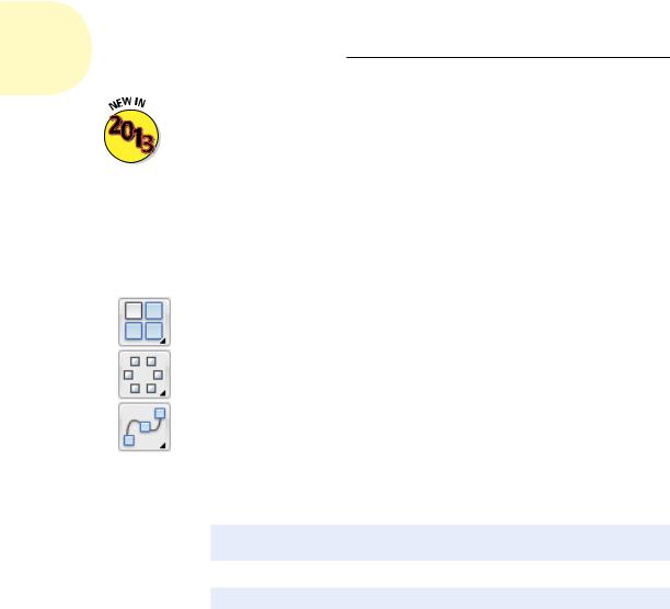
2.On the Home tab’s Modify panel, choose Rectangular Array from the Array drop-down list.
Choosing the specific array type from the drop-down list saves you from answering one prompt you’d get if you typed ARRAY.
When drop-down lists are available, the Ribbon remembers the last selection chosen. The Array button may show any one of three different icons. If you like the one that’s showing, you can simply select it instead of initiating the drop-down list.
3.At the Select Objects prompt, select one or more objects that you want to array.
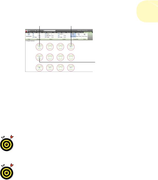
When you finish selecting, AutoCAD displays a three-row-by-four-column preview with six blue grips (shown in Figure 18-1) and prompts:
Select grip to edit array or [ASsociative/Base point/ COUnt/Spacing/COLumns/Rows/Levels/eXit]<eXit
If Dynamic input is turned on, the cursor prompt displays:
Select grip to edit or <eXit>:
The Ribbon changes to display the Array Creation contextual tab, as shown in Figure 18-1.
4.Enter the number of rows and columns of your source objects that you want to be arrayed, and also their spacing.
As we mention earlier, when AutoCAD 2012 introduced associative arrays, many people commented on what appeared to be a regressive step away from a dialog box and back to command window input. The good news is that AutoCAD 2013 gives you most of the advantages of both methods but few of the disadvantages — and adds yet another variant: the Ribbon.
www.it-ebooks.info
|
Chapter 18: Everything from Arrays to Xrefs 393 |
|
|
Row spacing |
Row and column quantity |
Row quantity
|
|
|
|
|
|
|
Column spacing |
Column quantity |
|
Base: move |
|
your array |
|
|
|
|
|||
Figure 18-1: You’re ready to dynamically define your associative array.
Start with the editing method that we believe most users will adopt — grip editing. As you play with the following options, observe how the dynamic preview constantly updates. Each grip controls a different aspect of your array, as follows:
•Row 1, column 1: Base. You can move your array to a different location as you create it. After you select this grip, you can drag and drop it to a new location (object snaps work), or you can enter X and Y values at the dynamic cursor prompt.
•Row 1, column 2: Column spacing. Drag this grip (or enter a value
at the dynamic prompt) to change the spacing of all columns.
You can enter a negative value, or you can drag to the left of row 1, column 1 to make your array grow in the opposite direction.
•Row 1, column 4: Column quantity. Drag this grip (or enter a value at the dynamic prompt) to change the quantity of columns.
•Column 1, row 2: Row spacing. Drag this grip (or enter a value at
the dynamic prompt) to change the spacing of all rows.
You can enter a negative value, or you can drag below row 1, column 1 to make your array grow in the opposite direction.
•Column 1, row 3: Row quantity. Drag this grip (or enter a value at the dynamic prompt) to change the quantity of rows.
•Row 3, column 4: Row and column quantity. Drag this grip (or enter values at the dynamic prompt) to change the quantity of rows and columns at the same time.
www.it-ebooks.info

394 Part IV: Advancing with AutoCAD
5.Check out the other methods of specifying your array.
The AutoCAD 2013 changes to the ARRAY interface give you three basic methods for defining your array. If you followed the scenario in this step list, you already played with grip editing. The interesting option is that the command window continues to show almost all the prompts. Typically, command-line input forces you to follow a specific sequence, but ARRAY in AutoCAD 2013 allows you to enter any command window option at any time.
Earlier, we mention that the Ribbon displays the Array Creation contextual tab while you’re defining your array. At any time, you can enter specific values for anything we have discussed so far, but it also has an extra functionality: the Columns and Rows tabs each have a Total window, referring to a total distance. If you enter values in either window, the column and/or row spacing will be adjusted so that the
number of rows and/or columns fit exactly within the specified distance.
6.Finish building your array.
If you don’t have a grip selected, the default mode is eXit. Simply press Enter or the spacebar, or click the Close Array button in the Ribbon, and you’re done!
But wait! There’s more! The Rows tab of the Array Creation contextual tab of the Ribbon includes options for vertical (Z axis) values. If you’re working in 3D, you can easily create a set of bleacher seats, for example, where the
higher-numbered rows are at a higher elevation so everyone gets a good view.
But it’s not even Christmas!
AutoCAD also has the ARRAYPOLAR command for creating polar (circular) arrays, such as the bolt holes in a pipe flange, horses on a carousel, or chambers in a revolver. As we indicate earlier, it may be hidden in the drop-down list under the Array button on the Modify tab of the Home panel of the Ribbon.
The basic principles of a polar array are the same as a rectangular one.
Each polar array is a single, associative object.
Objects within an array can be edited separately. We cover this a little later in this chapter.
As you create them, you see a dynamic preview of what the final array will look like.
You can specify your input to the command through grip edits, the command window, the dynamic cursor, and/or the Polar version of the Array Creation tab of the Ribbon.
www.it-ebooks.info

Chapter 18: Everything from Arrays to Xrefs 395
But polar arrays also have a few differences.
When you finish selecting the objects to be arrayed, you are asked for a center point for the array. Note that normal object snaps can be most helpful here.
After you select the center point, a six-item dynamic preview with editing grips appears, along with the polar variant of the Array Creation tab of the Ribbon.
Input specifications include
•The radius of the array
•The number of items in the array
•The angle to fill
A gear sector, for example, might need only ten teeth in a 60-degree segment.
•The number of rows
Although this seems to be strange terminology for a circular pattern, you can specify the number of concentric repeats of the circular pattern and the radial distance between them, like the growth rings of a tree.
•Whether items are rotated (for example, gear teeth) or not (Ferris wheel seats) as the array is produced
•The number of levels and the Z direction spacing between them
Down the garden path
Associative arrays have a third type that isn’t available when you use ARRAYCLASSIC or –ARRAY to produce a simple array.
Unlike rectangular and polar arrays, which require only source objects and some input parameters, path arrays require an additional piece of drawing geometry — a path. A path can be as simple as a line or a circle, or it can be a spline or a 2D or 3D polyline. Other than that, they behave very much like rectangular and polar arrays.
In the following steps, we show you how to use the ARRAYPATH command to bring some chairs to an elliptical dining room table and use the table itself as the path.
1.Open a drawing containing some objects you want to array along a path, or draw some simple geometry for your source object, and a line or an open or a closed spline or polyline for your path.
www.it-ebooks.info
396 Part IV: Advancing with AutoCAD
2.On the Home tab’s Modify panel, choose Path Array from the Array drop-down list.
Path Array may be hidden in the drop-down list under the Array button on the Modify tab of the Home panel of the Ribbon.
3.At the Select Objects prompt, select one or more objects that you want to array along a path.
AutoCAD prompts:
Select objects:
You can select any and all AutoCAD object types, including block insertions and text.
Object arraying is done based on the position of the objects relative to the starting end of the path object. If you want the arrayed objects to land on the path, they must be on the path before you select them.
When you finish selecting objects, AutoCAD prompts:
Select path curve:
4.Select the object you want to serve as the path.
Valid object types include straight lines, open or closed polylines and splines, arcs, circles, and ellipses, as well as helixes and 3D polylines.
You don’t have to press Enter after you select the path. AutoCAD immediately responds with a lengthy, multioption prompt, displays a dynamic preview, and displays the path version of the Array Creation contextual Ribbon tab.
5.Enter the specifications for your array.
As with rectangular and polar arrays, you can specify the number of items, the distance between them, and/or the length of a portion of the path to fill. A bit of experimentation will show that these options are often interrelated; changing one forces another one to change. You can also specify whether the arrayed objects stay horizontal, or whether they rotate to stay parallel to the path.
Again, just like the other array types, you can jump back and forth between grip editing, Ribbon entries, the command window options, and dynamic cursor input.
6.Finish building your array.
If you don’t have a grip selected, the default mode is eXit. Simply press Enter or the spacebar, or click the Close Array button in the Ribbon, and you’re done!
www.it-ebooks.info