

- •About the Authors
- •Dedication
- •Authors’ Acknowledgments
- •Table of Contents
- •Introduction
- •What’s Not (And What Is) in This Book
- •Mac attack!
- •Who Do We Think You Are?
- •How This Book Is Organized
- •Part I: AutoCAD 101
- •Part II: Let There Be Lines
- •Part III: If Drawings Could Talk
- •Part IV: Advancing with AutoCAD
- •Part V: On a 3D Spree
- •Part VI: The Part of Tens
- •But wait . . . there’s more!
- •Icons Used in This Book
- •A Few Conventions — Just in Case
- •Commanding from the keyboard
- •Tying things up with the Ribbon
- •Where to Go from Here
- •Why AutoCAD?
- •The Importance of Being DWG
- •Seeing the LT
- •Checking System Requirements
- •Suddenly, It’s 2013!
- •AutoCAD Does Windows (And Office)
- •And They’re Off: AutoCAD’s Opening Screens
- •Running with Ribbons
- •Getting with the Program
- •Looking for Mr. Status Bar
- •Let your fingers do the talking: The command window
- •The key(board) to AutoCAD success
- •Keeping tabs on palettes
- •Down the main stretch: The drawing area
- •Fun with F1
- •A Simple Setup
- •Drawing a (Base) Plate
- •Drawing rectangles on the right layers
- •Circling your plate
- •Nuts to you
- •Getting a Closer Look with Zoom and Pan
- •Modifying to Make It Merrier
- •Hip-hip-array!
- •Stretching out
- •Crossing your hatches
- •Following the Plot
- •A Setup Roadmap
- •Choosing your units
- •Weighing up your scales
- •Thinking annotatively
- •Thinking about paper
- •Defending your border
- •A Template for Success
- •Making the Most of Model Space
- •Setting your units
- •Making the drawing area snap-py (and grid-dy)
- •Setting linetype and dimension scales
- •Entering drawing properties
- •Making Templates Your Own
- •Setting Up a Layout in Paper Space
- •Will that be tabs or buttons?
- •View layouts Quick(View)ly
- •Creating a layout
- •Copying and changing layouts
- •Lost in paper space
- •Spaced out
- •A view(port) for drawing in
- •About Paper Space Layouts and Plotting
- •Managing Your Properties
- •Layer one on me!
- •Accumulating properties
- •Creating new layers
- •Manipulating layers
- •Using Named Objects
- •Using AutoCAD DesignCenter
- •Copying layers between drawings
- •Controlling Your Precision
- •Keyboard capers: Coordinate input
- •Understanding AutoCAD’s coordinate systems
- •Grab an object and make it snappy
- •Other Practical Precision Procedures
- •Introducing the AutoCAD Drawing Commands
- •The Straight and Narrow: Lines, Polylines, and Polygons
- •Toeing the line
- •Connecting the lines with polyline
- •Squaring off with rectangles
- •Choosing your sides with polygon
- •(Throwing) Curves
- •Going full circle
- •Arc-y-ology
- •Solar ellipses
- •Splines: The sketchy, sinuous curves
- •Donuts: The circles with a difference
- •Revision clouds on the horizon
- •Scoring Points
- •Commanding and Selecting
- •Command-first editing
- •Selection-first editing
- •Direct object manipulation
- •Choosing an editing style
- •Grab It
- •One-by-one selection
- •Selection boxes left and right
- •Perfecting Selecting
- •AutoCAD Groupies
- •Object Selection: Now You See It . . .
- •Get a Grip
- •About grips
- •A gripping example
- •Move it!
- •Copy, or a kinder, gentler Move
- •A warm-up stretch
- •Your AutoCAD Toolkit
- •The Big Three: Move, Copy, and Stretch
- •Base points and displacements
- •Move
- •Copy
- •Copy between drawings
- •Stretch
- •More Manipulations
- •Mirror
- •Rotate
- •Scale
- •Array
- •Offset
- •Slicing, Dicing, and Splicing
- •Trim and Extend
- •Break
- •Fillet and Chamfer and Blend
- •Join
- •When Editing Goes Bad
- •Zoom and Pan with Glass and Hand
- •The wheel deal
- •Navigating your drawing
- •Controlling your cube
- •Time to zoom
- •A View by Any Other Name . . .
- •Looking Around in Layout Land
- •Degenerating and Regenerating
- •Getting Ready to Write
- •Simply stylish text
- •Taking your text to new heights
- •One line or two?
- •Your text will be justified
- •Using the Same Old Line
- •Turning On Your Annotative Objects
- •Saying More in Multiline Text
- •Making it with Mtext
- •It slices; it dices . . .
- •Doing a number on your Mtext lists
- •Line up in columns — now!
- •Modifying Mtext
- •Gather Round the Tables
- •Tables have style, too
- •Creating and editing tables
- •Take Me to Your Leader
- •Electing a leader
- •Multi options for multileaders
- •How Do You Measure Up?
- •A Field Guide to Dimensions
- •The lazy drafter jumps over to the quick dimension commands
- •Dimension associativity
- •Where, oh where, do my dimensions go?
- •The Latest Styles in Dimensioning
- •Creating and managing dimension styles
- •Let’s get stylish!
- •Adjusting style settings
- •Size Matters
- •Details at other scales
- •Editing Dimensions
- •Editing dimension geometry
- •Editing dimension text
- •Controlling and editing dimension associativity
- •Batten Down the Hatches!
- •Don’t Count Your Hatches. . .
- •Size Matters!
- •We can do this the hard way. . .
- •. . . or we can do this the easy way
- •Annotative versus non-annotative
- •Pushing the Boundary (Of) Hatch
- •Your hatching has no style!
- •Hatch from scratch
- •Editing Hatch Objects
- •You Say Printing, We Say Plotting
- •The Plot Quickens
- •Plotting success in 16 steps
- •Get with the system
- •Configure it out
- •Preview one, two
- •Instead of fit, scale it
- •Plotting the Layout of the Land
- •Plotting Lineweights and Colors
- •Plotting with style
- •Plotting through thick and thin
- •Plotting in color
- •It’s a (Page) Setup!
- •Continuing the Plot Dialog
- •The Plot Sickens
- •Rocking with Blocks
- •Creating Block Definitions
- •Inserting Blocks
- •Attributes: Fill-in-the-Blank Blocks
- •Creating attribute definitions
- •Defining blocks that contain attribute definitions
- •Inserting blocks that contain attribute definitions
- •Edit attribute values
- •Extracting data
- •Exploding Blocks
- •Purging Unused Block Definitions
- •Arraying Associatively
- •Comparing the old and new ARRAY commands
- •Hip, hip, array!
- •Associatively editing
- •Going External
- •Becoming attached to your xrefs
- •Layer-palooza
- •Creating and editing an external reference file
- •Forging an xref path
- •Managing xrefs
- •Blocks, Xrefs, and Drawing Organization
- •Mastering the Raster
- •Attaching a raster image
- •Maintaining your image
- •Theme and Variations: Dynamic Blocks
- •Lights! Parameters!! Actions!!!
- •Manipulating dynamic blocks
- •Maintaining Design Intent
- •Defining terms
- •Forget about drawing with precision!
- •Constrain yourself
- •Understanding Geometric Constraints
- •Applying a little more constraint
- •AutoConstrain yourself!
- •Understanding Dimensional Constraints
- •Practice a little constraint
- •Making your drawing even smarter
- •Using the Parameters Manager
- •Dimensions or constraints — have it both ways!
- •The Internet and AutoCAD: An Overview
- •You send me
- •Send it with eTransmit
- •Rapid eTransmit
- •Bad reception?
- •Help from the Reference Manager
- •Design Web Format — Not Just for the Web
- •All about DWF and DWFx
- •Autodesk Design Review 2013
- •The Drawing Protection Racket
- •Autodesk Weather Forecast: Increasing Cloud
- •Working Solidly in the Cloud
- •Free AutoCAD!
- •Going once, going twice, going 123D
- •Your head planted firmly in the cloud
- •The pros
- •The cons
- •Cloudy with a shower of DWGs
- •AutoCAD 2013 cloud connectivity
- •Tomorrow’s Forecast
- •Understanding 3D Digital Models
- •Tools of the Trade
- •Warp speed ahead
- •Entering the third dimension
- •Untying the Ribbon and opening some palettes
- •Modeling from Above
- •Using 3D coordinate input
- •Using point filters
- •Object snaps and object snap tracking
- •Changing Planes
- •Displaying the UCS icon
- •Adjusting the UCS
- •Navigating the 3D Waters
- •Orbit à go-go
- •Taking a spin around the cube
- •Grabbing the SteeringWheels
- •Visualizing 3D Objects
- •Getting Your 3D Bearings
- •Creating a better 3D template
- •Seeing the world from new viewpoints
- •From Drawing to Modeling in 3D
- •Drawing basic 3D objects
- •Gaining a solid foundation
- •Drawing solid primitives
- •Adding the Third Dimension to 2D Objects
- •Creating 3D objects from 2D drawings
- •Modifying 3D Objects
- •Selecting subobjects
- •Working with gizmos
- •More 3D variants of 2D commands
- •Editing solids
- •Get the 2D Out of Here!
- •A different point of view
- •But wait! There’s more!
- •But wait! There’s less!
- •Do You See What I See?
- •Visualizing the Digital World
- •Adding Lighting
- •Default lighting
- •User-defined lights
- •Sunlight
- •Creating and Applying Materials
- •Defining a Background
- •Rendering a 3D Model
- •Autodesk Feedback Community
- •Autodesk Discussion Groups
- •Autodesk’s Own Bloggers
- •Autodesk University
- •The Autodesk Channel on YouTube
- •The World Wide (CAD) Web
- •Your Local ATC
- •Your Local User Group
- •AUGI
- •Books
- •Price
- •3D Abilities
- •Customization Options
- •Network Licensing
- •Express Tools
- •Parametrics
- •Standards Checking
- •Data Extraction
- •MLINE versus DLINE
- •Profiles
- •Reference Manager
- •And The Good News Is . . .
- •APERTURE
- •DIMASSOC
- •MENUBAR
- •MIRRTEXT
- •OSNAPZ
- •PICKBOX
- •REMEMBERFOLDERS
- •ROLLOVERTIPS
- •TOOLTIPS
- •VISRETAIN
- •And the Bonus Round
- •Index
Chapter 13: Text with Character 273
Using the Same Old Line
Despite its limitations, the TEXT command is useful for labels and other short notes for which MTEXT would be overkill. The following procedure shows you how to add text to your drawing by using AutoCAD’s TEXT command.
You can use TEXT for multiple lines of text: Just keep pressing Enter after you type each line of text, and TEXT puts the new line below the previous one. The problem with this approach is that TEXT creates each line of text as a separate object. If you want to add or remove words in those multiple lines later on, AutoCAD can’t do any word-wrapping for you; you have to edit each line separately, cutting words from one line and adding them to the adjacent line.
The TEXT command doesn’t use a dialog box, a fancy formatting toolbar, or a contextual Ribbon tab like the MTEXT command’s In-Place Text Editor. You set options by typing them into the command line or the Dynamic Input tooltip.
Here’s how you add text with the TEXT command:
1.Set an appropriate text style current, as described in the section “Simply stylish text,” earlier in this chapter.
It’s possible to set an already created text style current at the TEXT command prompt, but it’s usually more straightforward to set the style before starting the command.
An alternative to opening the Text Style dialog box to make an existing style current is to click the Text Style drop-down list and choose the style there. Look for the Text Style drop-down list on the Annotation panel’s slideout (Home tab) or the Text panel of the Annotate tab.
2.(Optional) Use the Object Snap button on the status bar to enable or disable running object snaps.
You may or may not want to snap text to existing objects. For example, you’d want to use a Center object snap to locate a letter or number precisely at the center of a circle. Make sure that you specify middle-center (MC) justification for the text to ensure that this works perfectly.
3.On the Home tab’s Annotation panel, click the lower part of the big button labeled Text, and then choose Single Line from the drop-down menu to start the TEXT command.
Don’t click the upper part of the Text button — that starts the multiline text command, MTEXT, which we cover in the next section.
If your text style is annotative and this is the first annotative object you’re creating in this drawing session, AutoCAD usually displays a Select Annotation Scale dialog box, which advises you that you are
www.it-ebooks.info

274 Part III: If Drawings Could Talk
indeed creating an annotative object and asks you to set the scale at which you want the annotation to appear; click OK to continue. Later, we explain how and why to turn this annoying dialog box off.
AutoCAD tells you the current text style and height settings and prompts you to select a starting point for the text or to choose an option for changing the text justification or current text style first:
Current text style: “Standard” Text height: 0.2000 Annotative: No
Specify start point of text or [Justify/Style]:
If the text style is annotative, the text height displayed in the prompt is the model space height, not the ultimate plotted text height. For example, if the text style is created with a fixed paper text height of 0.2000, and the annotation scale is set to 1:2, the AutoCAD prompt will read
Text height: 0.4000.
4.If you want a different justification from the default (Left), type J, press Enter, and choose one of the other justification options.
Look up create single-line text in the online help system if you need help with the justification options.
5.Specify the insertion point for the first text character.
You can enter the point’s coordinates from the keyboard, use the mouse to click a point onscreen, or press Enter to locate new text immediately below the most recent single-line text object that you created.
AutoCAD prompts you for the text height (or the paper height if the text style is annotative):
Specify height <0.2000>:
6.Specify the height for the text.
This prompt doesn’t appear if you’re using a text style with a fixed (that is, nonzero) height. See the “Simply stylish text” section, earlier in this chapter, for information about fixed versus variable text heights.
AutoCAD prompts you for the text rotation angle:
Specify rotation angle of text <0>:
7.Specify the text rotation angle by typing the rotation angle and pressing Enter or by rotating the line onscreen with the mouse.
AutoCAD prompts you to type the text.
8.Type the first line of text and press Enter.
9.Type additional lines of text, pressing Enter at the end of each line.
Figure 13-2 shows text appearing onscreen as you type it (or it would if this book had animated pages).
www.it-ebooks.info
Chapter 13: Text with Character 275
Figure 13-2: Single-line text appears letter by letter.
10.To stop entering text and return to the command prompt, press Enter at the start of a blank line.
AutoCAD adds the new single-line text object — or objects, if you typed more than one line — to the drawing.
To align lines of text exactly, make sure that you type all the lines in one instance of the TEXT command, pressing Enter after each line to make the next line appear just after it. Otherwise, aligning different lines of text precisely is harder to do (unless you set your snap just right or use a complicated combination of object snaps and point filters). To edit single-line text after you’ve created it, select the text, right-click, and choose Edit (or double-click the text) to open the In-Place Text Editor. (In-place simply means that you edit text at its exact size and location in the drawing.) We tell you more about inplace text editing in the section “Making it with Mtext,” later in this chapter.
An in-place editing box highlights the selected text object, enabling you to edit the contents of the text string. If you want to edit other text properties such as text height, select the text, right-click, and choose Properties to display the Properties palette. Use the Properties palette to change parameters as needed.
If the Quick Properties button on your application status bar is enabled, clicking a single-line text object opens the Quick Properties panel, allowing you to change some (but not all) of the same properties as the Properties palette.
www.it-ebooks.info
276 Part III: If Drawings Could Talk
Turning On Your Annotative Objects
Annotative objects were introduced in AutoCAD 2008, ending 25 years of calculating agony, but a quick show of hands at Autodesk University and AUGI CAD Camp classes reveals that on average only about 20 percent have ever tried them — and most of them gave up and went back to the old way because they thought they weren’t working. There’s a very simple explanation for this, which we come to in a moment.
Here’s a quick example that shows how things are supposed to work. Make sure that you are in model space.
1.Set the annotation controls.
In the lower-right corner of the AutoCAD screen, you’ll find three buttons with variants of a triangular symbol. They represent the end view of an engineer’s triangular scale; an old-timer in your office should be able to show you one and how they worked. Click the center and righthand buttons, the ones without the numbers beside them, until they are grayed out and don’t show a small yellow splash in them. If the left-hand button doesn’t display the numbers 1:1, click it and select 1:1 from the drop-down list.
2.Select an annotative text style.
Use the STYLE command as described previously in the “Get in style” section and set the Annotative style to be current. Set its Paper Text Height to 0.125.
3.Create some text.
Use the TEXT command and create a line of text that says Scale 1:1.
The first time you place annotative text, you’re asked to select a drawing scale, and it defaults to the current scale, which is probably what you want anyway. Eventually this becomes a nuisance, so the check box lets you turn it off.
4.Change the drawing scale.
Click the left-hand annotative control button and select 1:2 from the drop-down list. This sets the current drawing scale to 1:2. Hey, the first piece of text disappears! Not to worry; that’s what it’s supposed to do.
5.Create some text.
Use the TEXT command again and create a line of text that says Scale 1:2, and another one that says Both scales. Note that they are twice as tall as the now-invisible Scale 1:1 text.
www.it-ebooks.info

Chapter 13: Text with Character 277
6.Change the drawing scale.
Click the left-hand annotative control button and select 1:1 from the drop-down list. Interesting! The first piece of text reappears, but the other two disappear!
7.Add another scale to an object.
Click the left-hand annotative control button and select 1:2 from the drop-down list. Now click the Both scales text and then right-click. Select Annotative Object Scale, and then select Add/Delete Scales. When the dialog box appears, click the Add button in the upper-right corner and then select 1:1 from the list. Click OK, and then OK again, to return to the drawing screen.
8.Change the drawing scale.
Click the left-hand annotative control button and select 1:1 from the drop-down list. Interesting! The Scale 1:1 text reappears, Scale 1:2 disappears, and Both scales changes size to match the height of Scale 1:1 text!
9.Change the drawing scale again.
Click the left-hand annotative control button and select 1:5 from the drop-down list. All three text items disappear!
As indicated earlier, that’s how annotative objects, including text, dimensions (discussed Chapter 14), hatch patterns (Chapter 15), and blocks (Chapter 17) are supposed to work. Upon creation, they automatically size themselves
to suit the current drawing scale, they’re visible only when their annotation scales match the current drawing scale, and they can have more than one scale attached, so they’re visible in more than one drawing scale setting.
Better yet, they exhibit this same behavior in paper space viewports. It thus becomes trivially easy to set up drawings with details at other scales. We cover this in more detail in Chapter 14.
If an annotative object has multiple scales attached and you edit its location at one scale, this doesn’t affect its location at the other scales.
But wait! There’s more! When viewing an object with multiple scales, you aren’t looking at a copy of the object but instead you see a different configuration of the same object. To see this, edit the contents of your Both scales text object to say something else. The new contents automatically appear at all scale representations of that object.
Now we reveal the dirty, dark secret as to why most people gave up on them. It all gets back to Step 1 in the preceding instructions. By default, the middleand right-hand buttons are both turned on, but we had you turn them off. Turn the middle button back on and observe that now all annotative objects at all scales
www.it-ebooks.info
278 Part III: If Drawings Could Talk
are always visible, no matter what the value of the current drawing scale, even if none of the objects has a scale that matches the current drawing scale.
But wait! It gets worse! If you turn on the right-hand button and then change the drawing scale, every annotation object retroactively gets the current scale added to it.
It’s easy to see how the last two statements would easily confuse people into not understanding how annotative objects work. We can think of only one situation where you would want all objects to retroactively receive the new drawing scale, and that would be where you have created a drawing with the intention of printing it at a specific scale, and then you decide that you need to change the scale to suit a different printer or paper size.
Most of the time, for most people, there are way too many scales listed in the Add Scales to Object dialog box. AutoCAD has a handy-dandy Edit Drawing Scales dialog box that lets you remove those imperial scales from your current drawing if you never work in feet and inches. (And vice versa, for the metrically challenged.) To run through your scales, choose Scale List on the Annotation Scaling panel of the Ribbon’s Annotate tab. If you make a mistake, the Reset button will restore all the default scales. You can remove those extra scales for all your drawing in the Default Scale List dialog box, accessible on the User Preferences tab of the Options dialog box.
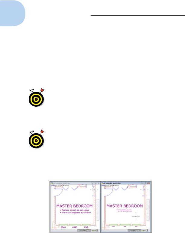
You can display the drawing status bar (shown in Figures 13-2 and 13-3) by clicking the down arrow near the right end of the application status bar to open the application status bar menu, and then choosing Drawing Status Bar.
Figure 13-3 shows two versions of the same drawing, with the same text objects (the bulleted notes and windows sizes) and wall hatching displaying at the different annotation scales specified in the two status bars. The non-annotative text (the room label) remains unchanged. (we cover hatching your drawings in Chapter 15.)
Figure 13-3: Annotative objects resize automatically as the annotation scale changes.
www.it-ebooks.info