

- •About the Authors
- •Dedication
- •Authors’ Acknowledgments
- •Table of Contents
- •Introduction
- •What’s Not (And What Is) in This Book
- •Mac attack!
- •Who Do We Think You Are?
- •How This Book Is Organized
- •Part I: AutoCAD 101
- •Part II: Let There Be Lines
- •Part III: If Drawings Could Talk
- •Part IV: Advancing with AutoCAD
- •Part V: On a 3D Spree
- •Part VI: The Part of Tens
- •But wait . . . there’s more!
- •Icons Used in This Book
- •A Few Conventions — Just in Case
- •Commanding from the keyboard
- •Tying things up with the Ribbon
- •Where to Go from Here
- •Why AutoCAD?
- •The Importance of Being DWG
- •Seeing the LT
- •Checking System Requirements
- •Suddenly, It’s 2013!
- •AutoCAD Does Windows (And Office)
- •And They’re Off: AutoCAD’s Opening Screens
- •Running with Ribbons
- •Getting with the Program
- •Looking for Mr. Status Bar
- •Let your fingers do the talking: The command window
- •The key(board) to AutoCAD success
- •Keeping tabs on palettes
- •Down the main stretch: The drawing area
- •Fun with F1
- •A Simple Setup
- •Drawing a (Base) Plate
- •Drawing rectangles on the right layers
- •Circling your plate
- •Nuts to you
- •Getting a Closer Look with Zoom and Pan
- •Modifying to Make It Merrier
- •Hip-hip-array!
- •Stretching out
- •Crossing your hatches
- •Following the Plot
- •A Setup Roadmap
- •Choosing your units
- •Weighing up your scales
- •Thinking annotatively
- •Thinking about paper
- •Defending your border
- •A Template for Success
- •Making the Most of Model Space
- •Setting your units
- •Making the drawing area snap-py (and grid-dy)
- •Setting linetype and dimension scales
- •Entering drawing properties
- •Making Templates Your Own
- •Setting Up a Layout in Paper Space
- •Will that be tabs or buttons?
- •View layouts Quick(View)ly
- •Creating a layout
- •Copying and changing layouts
- •Lost in paper space
- •Spaced out
- •A view(port) for drawing in
- •About Paper Space Layouts and Plotting
- •Managing Your Properties
- •Layer one on me!
- •Accumulating properties
- •Creating new layers
- •Manipulating layers
- •Using Named Objects
- •Using AutoCAD DesignCenter
- •Copying layers between drawings
- •Controlling Your Precision
- •Keyboard capers: Coordinate input
- •Understanding AutoCAD’s coordinate systems
- •Grab an object and make it snappy
- •Other Practical Precision Procedures
- •Introducing the AutoCAD Drawing Commands
- •The Straight and Narrow: Lines, Polylines, and Polygons
- •Toeing the line
- •Connecting the lines with polyline
- •Squaring off with rectangles
- •Choosing your sides with polygon
- •(Throwing) Curves
- •Going full circle
- •Arc-y-ology
- •Solar ellipses
- •Splines: The sketchy, sinuous curves
- •Donuts: The circles with a difference
- •Revision clouds on the horizon
- •Scoring Points
- •Commanding and Selecting
- •Command-first editing
- •Selection-first editing
- •Direct object manipulation
- •Choosing an editing style
- •Grab It
- •One-by-one selection
- •Selection boxes left and right
- •Perfecting Selecting
- •AutoCAD Groupies
- •Object Selection: Now You See It . . .
- •Get a Grip
- •About grips
- •A gripping example
- •Move it!
- •Copy, or a kinder, gentler Move
- •A warm-up stretch
- •Your AutoCAD Toolkit
- •The Big Three: Move, Copy, and Stretch
- •Base points and displacements
- •Move
- •Copy
- •Copy between drawings
- •Stretch
- •More Manipulations
- •Mirror
- •Rotate
- •Scale
- •Array
- •Offset
- •Slicing, Dicing, and Splicing
- •Trim and Extend
- •Break
- •Fillet and Chamfer and Blend
- •Join
- •When Editing Goes Bad
- •Zoom and Pan with Glass and Hand
- •The wheel deal
- •Navigating your drawing
- •Controlling your cube
- •Time to zoom
- •A View by Any Other Name . . .
- •Looking Around in Layout Land
- •Degenerating and Regenerating
- •Getting Ready to Write
- •Simply stylish text
- •Taking your text to new heights
- •One line or two?
- •Your text will be justified
- •Using the Same Old Line
- •Turning On Your Annotative Objects
- •Saying More in Multiline Text
- •Making it with Mtext
- •It slices; it dices . . .
- •Doing a number on your Mtext lists
- •Line up in columns — now!
- •Modifying Mtext
- •Gather Round the Tables
- •Tables have style, too
- •Creating and editing tables
- •Take Me to Your Leader
- •Electing a leader
- •Multi options for multileaders
- •How Do You Measure Up?
- •A Field Guide to Dimensions
- •The lazy drafter jumps over to the quick dimension commands
- •Dimension associativity
- •Where, oh where, do my dimensions go?
- •The Latest Styles in Dimensioning
- •Creating and managing dimension styles
- •Let’s get stylish!
- •Adjusting style settings
- •Size Matters
- •Details at other scales
- •Editing Dimensions
- •Editing dimension geometry
- •Editing dimension text
- •Controlling and editing dimension associativity
- •Batten Down the Hatches!
- •Don’t Count Your Hatches. . .
- •Size Matters!
- •We can do this the hard way. . .
- •. . . or we can do this the easy way
- •Annotative versus non-annotative
- •Pushing the Boundary (Of) Hatch
- •Your hatching has no style!
- •Hatch from scratch
- •Editing Hatch Objects
- •You Say Printing, We Say Plotting
- •The Plot Quickens
- •Plotting success in 16 steps
- •Get with the system
- •Configure it out
- •Preview one, two
- •Instead of fit, scale it
- •Plotting the Layout of the Land
- •Plotting Lineweights and Colors
- •Plotting with style
- •Plotting through thick and thin
- •Plotting in color
- •It’s a (Page) Setup!
- •Continuing the Plot Dialog
- •The Plot Sickens
- •Rocking with Blocks
- •Creating Block Definitions
- •Inserting Blocks
- •Attributes: Fill-in-the-Blank Blocks
- •Creating attribute definitions
- •Defining blocks that contain attribute definitions
- •Inserting blocks that contain attribute definitions
- •Edit attribute values
- •Extracting data
- •Exploding Blocks
- •Purging Unused Block Definitions
- •Arraying Associatively
- •Comparing the old and new ARRAY commands
- •Hip, hip, array!
- •Associatively editing
- •Going External
- •Becoming attached to your xrefs
- •Layer-palooza
- •Creating and editing an external reference file
- •Forging an xref path
- •Managing xrefs
- •Blocks, Xrefs, and Drawing Organization
- •Mastering the Raster
- •Attaching a raster image
- •Maintaining your image
- •Theme and Variations: Dynamic Blocks
- •Lights! Parameters!! Actions!!!
- •Manipulating dynamic blocks
- •Maintaining Design Intent
- •Defining terms
- •Forget about drawing with precision!
- •Constrain yourself
- •Understanding Geometric Constraints
- •Applying a little more constraint
- •AutoConstrain yourself!
- •Understanding Dimensional Constraints
- •Practice a little constraint
- •Making your drawing even smarter
- •Using the Parameters Manager
- •Dimensions or constraints — have it both ways!
- •The Internet and AutoCAD: An Overview
- •You send me
- •Send it with eTransmit
- •Rapid eTransmit
- •Bad reception?
- •Help from the Reference Manager
- •Design Web Format — Not Just for the Web
- •All about DWF and DWFx
- •Autodesk Design Review 2013
- •The Drawing Protection Racket
- •Autodesk Weather Forecast: Increasing Cloud
- •Working Solidly in the Cloud
- •Free AutoCAD!
- •Going once, going twice, going 123D
- •Your head planted firmly in the cloud
- •The pros
- •The cons
- •Cloudy with a shower of DWGs
- •AutoCAD 2013 cloud connectivity
- •Tomorrow’s Forecast
- •Understanding 3D Digital Models
- •Tools of the Trade
- •Warp speed ahead
- •Entering the third dimension
- •Untying the Ribbon and opening some palettes
- •Modeling from Above
- •Using 3D coordinate input
- •Using point filters
- •Object snaps and object snap tracking
- •Changing Planes
- •Displaying the UCS icon
- •Adjusting the UCS
- •Navigating the 3D Waters
- •Orbit à go-go
- •Taking a spin around the cube
- •Grabbing the SteeringWheels
- •Visualizing 3D Objects
- •Getting Your 3D Bearings
- •Creating a better 3D template
- •Seeing the world from new viewpoints
- •From Drawing to Modeling in 3D
- •Drawing basic 3D objects
- •Gaining a solid foundation
- •Drawing solid primitives
- •Adding the Third Dimension to 2D Objects
- •Creating 3D objects from 2D drawings
- •Modifying 3D Objects
- •Selecting subobjects
- •Working with gizmos
- •More 3D variants of 2D commands
- •Editing solids
- •Get the 2D Out of Here!
- •A different point of view
- •But wait! There’s more!
- •But wait! There’s less!
- •Do You See What I See?
- •Visualizing the Digital World
- •Adding Lighting
- •Default lighting
- •User-defined lights
- •Sunlight
- •Creating and Applying Materials
- •Defining a Background
- •Rendering a 3D Model
- •Autodesk Feedback Community
- •Autodesk Discussion Groups
- •Autodesk’s Own Bloggers
- •Autodesk University
- •The Autodesk Channel on YouTube
- •The World Wide (CAD) Web
- •Your Local ATC
- •Your Local User Group
- •AUGI
- •Books
- •Price
- •3D Abilities
- •Customization Options
- •Network Licensing
- •Express Tools
- •Parametrics
- •Standards Checking
- •Data Extraction
- •MLINE versus DLINE
- •Profiles
- •Reference Manager
- •And The Good News Is . . .
- •APERTURE
- •DIMASSOC
- •MENUBAR
- •MIRRTEXT
- •OSNAPZ
- •PICKBOX
- •REMEMBERFOLDERS
- •ROLLOVERTIPS
- •TOOLTIPS
- •VISRETAIN
- •And the Bonus Round
- •Index

Chapter 16: The Plot Thickens 343
There! — 16 steps, as promised. On the other hand, we never promised that this plot would be usable. For example, if you tried to plot a large, complex D-size or E-size architectural drawing on an A-size sheet of paper, it won’t be very readable without a microscope. The bottom line, however, is that you produced a plot! Read the rest of this chapter for all the details about the numerous other plotting options available in AutoCAD. If you had trouble with this quick plot, you may want to jump ahead in this chapter to the troubleshooting section, “The Plot Sickens,” later in this chapter.
Get with the system
One of the complications you face in your attempts to create a hard copy is that AutoCAD has two distinct ways of communicating with your plotters and printers. Operating systems, and the programs that run on them, use a
special piece of software called a printer driver to format data for printing and then send it to the printer or plotter. When you configure Windows to recognize a new printer connected to your computer or your network, you’re actually installing the printer’s driver. AutoCAD, like other Windows programs, works with the printers you’ve configured in Windows. AutoCAD calls these system printers because they’re part of the Windows operating system.
But AutoCAD, unlike other Windows programs, can’t leave well enough alone. Some output devices, especially some larger plotters, aren’t controlled very efficiently by the Windows system printer drivers. For that reason, AutoCAD comes with specialized nonsystem drivers (that is, drivers that are not installed as part of the Windows system) for plotters from companies such as Hewlett-Packard, Xerox, KIP, and Océ. These drivers ignore the tidy rules for communicating with Windows printers in order to get things done a bit more quickly and flexibly.
Most of the time, using already-configured Windows system printers is easiest, and they work well with many devices, especially devices such as laser and inkjet printers that print on smaller paper. However, if you have a largeformat plotter, you may be able to get faster plotting, better plot quality, or more plot features by installing a nonsystem driver. To find out more, choose Installation & Deployment Driver and Peripheral Guide Use Plotters and Printers on the AutoCAD online help system’s home page.
Configure it out
For now, you should simply make sure that AutoCAD recognizes the devices that you want to use for plotting. The following steps show you how:
1.Launch AutoCAD and open an existing drawing or start a new, blank drawing.
www.it-ebooks.info
344 Part III: If Drawings Could Talk
2.Choose Options on the Application Menu — or type OP and press
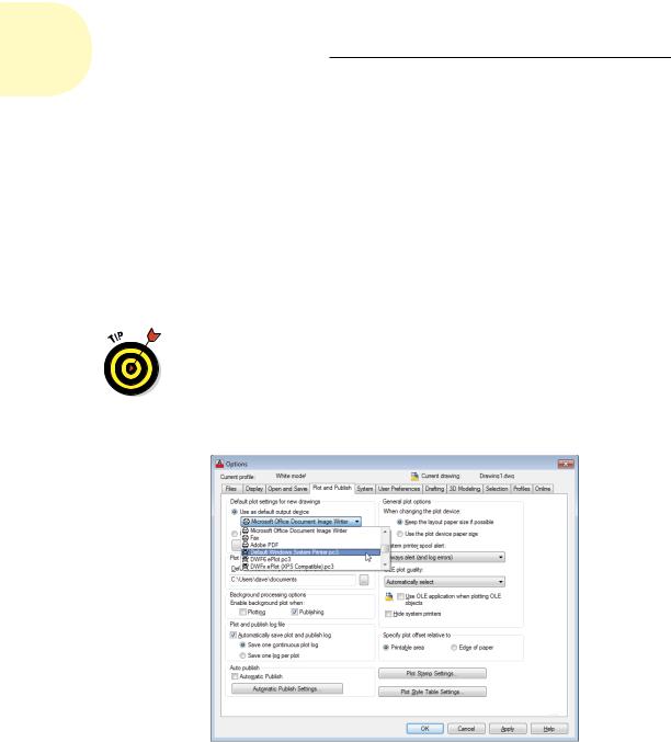
Enter — to open the Options dialog box; then click the Plot and Publish tab.
3.Click the drop-down arrow to view the list just below the Use as Default Output Device option, as shown in Figure 16-4.
The list includes two kinds of device configurations, designated by two tiny, difficult-to-distinguish icons to the left of the device names:
•Windows: A little printer icon with a sheet of white paper coming out the top indicates a Windows system printer configuration.
•Nonsystem: A little plotter-with-legs icon with a piece of paper coming out the front indicates a nonsystem (that is, AutoCADspecific) configuration.
The nonsystem configuration names always end in .pc3 because they’re stored in special AutoCAD Plotter Configuration version 3 files. So, if you can’t distinguish the difference between the icons, look for the .pc3 at the end of the name.
System printers |
List of devices |
||||
|
|
|
|
|
|
|
|
|
|
|
|
|
|
|
|
|
|
|
|
|
|
|
|
|
|
|
|
|
|
|
|
|
|
|
|
|
|
|
|
|
|
|
|
|
|
|
|
Non-system printers
Figure 16-4: System and nonsystem printer configurations.
www.it-ebooks.info

Chapter 16: The Plot Thickens 345
4.Verify that the list includes the printers and plotters that you want to have available in AutoCAD.
If they’re not in the list, how you add one depends on your operating system:
•Windows XP: Choose Start Printers and Faxes and then click the Add a Printer link under Printer Tasks on the left side of the window.
•Windows Vista: Choose Start Control Panel Hardware and Sound Printers Add a Printer and then click Add a Local Printer.
•Windows 7: Choose Start Devices and Printers Add a Printer and then click Add a Local Printer.
If your printer isn’t in the default Windows list, cancel the wizard and hunt down a driver disc that came with your printer. Better yet, download the current driver from the printer manufacturer’s website.
5.Choose the output device that you want to make the default for new drawings.
6.Click OK to close the dialog box and retain any changes that you made in the previous step.
You use the AutoCAD Plotter Manager’s Add-a-Plotter Wizard to create nonsystem driver configurations. (Choose Plotter Manager on the Plot panel of the Ribbon’s Output tab to display an Explorer window containing a shortcut to the wizard.) This wizard is similar to the Windows Add Printer Wizard; if you can handle adding an ordinary printer in Windows, you can probably handle adding a nonsystem plotter configuration to AutoCAD. When you complete the wizard steps, AutoCAD saves the information in a PC3 (Plotter Configuration version 3) file. If you add an HP Designjet printer or certain Océ wide-format printers, you will be advised by the Add-a-Plotter Wizard to exit and instead install the device as a Windows system printer (for more information, choose Installation & Deployment Driver and Peripheral Guide Use Plotters and Printers Set Up Plotters and Printers from the online help system’s home page). Many people find that the standard drivers work fine, but as we mention later in this chapter, custom drivers may include additional paper sizes as well as other handy settings.
Preview one, two
One of the keys to efficient plotting is liberal use of AutoCAD’s preview feature. (To maintain political balance, we recommend conservative use of some other AutoCAD options elsewhere in the book.)
www.it-ebooks.info

346 Part III: If Drawings Could Talk
The postage stamp–sized partial preview in the middle of the Plot dialog box is a quick reality check to make sure that your plot fits on the paper and is turned in the right direction. If the plot area at the current scale is too large for the paper, AutoCAD displays thick red warning lines along the side(s) of the sheet where the drawing will be truncated.
Click the Preview button to see a full preview in a separate window. You see exactly how your drawing lays out on the paper as well as how the various lineweights, colors, and other object plot properties will appear. You can zoom and pan around the preview by using the right-click menu.
Any zooming or panning that you do won’t affect what area of the drawing gets plotted. Zooming and panning is just a way to get a better look at different areas of the plot preview.
Instead of fit, scale it
In most real plotting situations, you want to plot to a specific scale rather than let AutoCAD choose some oddball scale that just happens to maximize the drawing on the paper. And if you’re going to plot the Model tab of a drawing to scale, you need to know its drawing scale factor. Chapter 4 describes setup concepts, and Chapter 13 provides some tips for determining the scale factor of a drawing that someone else created.
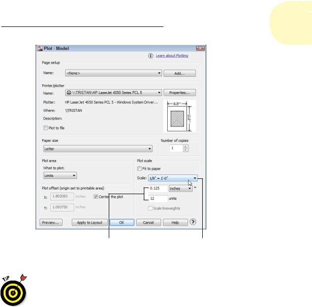
If your drawing was created at a standard scale, such as 1:50 or 1/4" = 1'–0", you simply choose the scale from the handy Scale drop-down list in the Plot dialog box. If your scale isn’t in the list, type the ratio between plotted distance and AutoCAD drawing distance into the two text boxes below the Scale drop-down list, as shown in Figure 16-5. Usually the easiest way to express the ratio is to type 1 in the upper box and the drawing scale factor in the lower box. (See Chapter 4 for more information.)
Your CAD manager may have edited the Scale drop-down list to add uncommon scales or remove scales that your company never uses. If you’re designing espresso machines in Milano, for example, you’ll probably never need to plot your drawings at 1/128" = 1'–0".
Creating half-size plots for some purposes is common in some industries. To plot model space half-size, double the drawing scale factor. For example, a 1/8" = 1'–0" drawing has a drawing scale factor of 96, which is equivalent to a plot scale of 1 = 96. To make a half-size model space plot of it, specify a plot scale of 1 = 192 (or choose 1/16" = 1'–0" from the Scale drop-down list).
www.it-ebooks.info
Chapter 16: The Plot Thickens 347
Type a ratio... ...or choose a prede ned scale.
Figure 16-5: Lots of ways to scale.
Even if you work with drawings created to be plotted at a specific scale, plotting with a Fit to Paper scale may be the most efficient way to make a reduced-size check plot. For example, drafters in your office might create drawings that get plotted on D-size sheets (24 x 36 inches), whereas you have access to a laser printer with a B-size (11 x 17 inches) paper tray. By plotting the D-size drawings scaled to fit on B-size paper, you end up with check plots that are slightly smaller than half size. You won’t be able to measure distances on the check plots with a scale, but you can give them a visual check for overall correctness.
www.it-ebooks.info