

Navigation and Signal Lights
Navigation Light System
Feeder
Navigation lights (mast head, side and stern lights) are to be fed by their own exclusive distribution board located on the navigation bridge. The distribution board is to be supplied from the main as well as from the emergency source of power. A means to transfer the power source is to be fitted on the navigation bridge.
Branch Circuit
Each navigation light is to have its own branch circuit, and each branch circuit is to be fitted with a protective device.
Duplicate Lamp
Each navigation light is to be fitted with duplicate lamps.
Control and Indication Panel
A control and indication panel for the navigation lights is to be provided on the navigation bridge. The panel is to be fitted with the following functions:
A means to disconnect each navigation light.
An indicator for each navigation light.
Automatic visual and audible warning in the event of failure of a navigation light. If a visual signal device is connected in series with the navigation light, the failure of this device is not to cause the extinction of the navigation light. The audible device is to be connected to a separate power supply so that the audible alarm may still be activated in the event of power or circuit failure to the navigation lights.
Summary of Regulations
The navigation lights must be connected directly or through a transformer to the main or emergency switchboard i.e., no switches are to be in between the source and the dedicated distribution board. The distribution board must be easily accessible to the officer of the watch.
The masthead, side and stern lights shall be connected separately to the above distribution board which is reserved for this purpose.
Each light shall be controlled' and protected in each insulated pole by a switch and fuses or by a circuit breaker mounted on the above distribution board (in case of failure of the ship's mains, the double pole switch may be changed over to an emergency source of supply).
The bulb shall provide a uniform intensity output as mentioned in Table 22.7 below -hence a cage winding is used.
Each light shall be provided by an automatic insulator which gives an audible and / or visual warning in the event of an extinction of the light. If an audio device alone is used, it shall be connected to a separate source of supply - e.g., a battery. If a visual signal is used, which is in series with the light, means must be provided to prevent the extinction of the light owing to the failure of the visual signal.
The visual device must be so connected that its failure does not extinguish the navigation light circuit.
(g) Provision shall be made on the bridge for such navigational lights to be transferred to an alternative circuit.
|
Lamp |
Intensity |
|
Main Mast Lamp |
94 Cd |
|
Side Lamp |
12 Cd |
|
Stern Lamp |
12 Cd |
|
Low Lamp |
12 Cd |
|
Other Navigation Lights |
12 Cd |
Table 22-7 - Intensity Requirements of Lamps
The International Maritime Organisation (IMO) and National Authorities prescribe the number, position and power rating of navigation lights aboard ships. By far the most common arrangement is to have five specially designed navigation 'running' lights referred to as Fore mast, Main mast (or Aft mast), Port, Starboard and Stern. Two anchor lights fitted forward and aft, may also be controlled from the Navigation Light Panel. The sidelights are red for port and green for starboard while the other lights are white. Special incandescent filament lamps are used each with a power rating of 65W, but 60W and 40W ratings are permitted in some cases.
Due to the essential safety requirement for navigation lights, it is becoming a common practice to have two fittings at each position, or two lamps and lamp-holders within a special dual fitting. Each light is separately supplied, switched, fused and monitored from a Navigation Light Indicator Panel in the wheelhouse. The electric power is provided usually at 220V a.c. with a 'main' supply fed from the section of the main switchboard that is meant for the essential services. (Refer Figures 3.9 and 4.2). An 'alternative' or 'stand by' power supply is fed from the emergency switchboard. A changeover switch on the Navigation Light Panel is used to select the main or standby power supply.
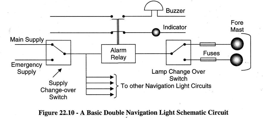
The Navigation Light Indicator Panel has indicator lamps and an audible alarm to warn of any lamp or lamp-circuit failure. Each lamp-circuit has an alarm relay which monitors the lamp's current. The relay may be electromagnetic or electronic. A basic double navigation light's schematic circuit with alternative power supplies is shown in Figure 22.10. A similar circuit is shown in Figure 22.11.
Obviously the light fittings are in exposed positions, so during maintenance checks, one should concentrate on water-tightness and on the condition of the supply cable.

Operation
Referring to Figure 22.11, when the double pole switch is closed the navigation light is illuminated. Current in the relay circuit causes the relay coil to energise, which pulls the NC (normally closed) contact open so that the audio alarm (buzzer) circuit is now open. Only a low voltage lamp is needed for the indicating lamp. This ensures a small voltage drop across that part of the circuit. Keeping regulatory requirements in mind, if the indicating lamp fails, the circuit is completed through the back-up resistor, so the navigation light does not fail.
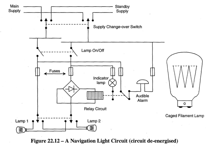
If the navigation light fails, or if a fuse blows, the current in the circuit ceases and the relay is de-energised. The NC contact springs back to activate the buzzer circuit. In case of failure of the ship's mains, the double pole switch may be changed over to emergency supply. A similar circuit is depicted in Figure 22.12. The recommended caged filament lamp is also shown. Caged filaments last longer as they can withstand shock and vibration.
Now various signal lights with colours of red, green, white, and blue are arranged on the signal mast. These lights are switched-on to provide a particular combination in order to signal states relating to various international and national regulations. Pilotage requirements, health, dangerous cargo condition, etc., are signalled with these lights. White Morse code flashing lights may also be fitted on the signal mast.
The NUC (Not Under Command) state is signalled using up to two all-round red lights (depending on the length of the vessel), vertically mounted and at least 2 metres apart. Such important lights are fed from the 24V d.c. emergency supply system but some ships may also have an additional NUC light-pair fed from the 220V a.c. emergency power supply.
Lights and signals are to be exhibited appropriately to other ships so as to indicate whether the vessel is under way, at anchor, not under command or even aground. The required lights are to be shown from sunset to sunrise, and also during bad visibility.
Note:
A ship is 'Under Way' when she has no ropes running ashore or to the buoy, nor is she at anchor or aground.
A ship is 'Not Under Command' generally when either the propeller or the rudder is not functioning satisfactorily.