

Cathodic Protection
The Electrochemical Theory of Corrosion
The electrochemical theory of corrosion states that corrosion proceeds by an anodic or oxidation reaction and a cathodic or reduction reaction.
Hydroxyl ions migrate through the water to the anode, here combining with the iron ions to form Fe(OH)2 which combines with dissolved oxygen to form Fe(OH)3 or rust. In this way the anodic area will corrode. To prevent this it would be necessary to make the entire hull cathodic. Therefore, forcing electrons onto the metal will stop its corrosion. This technique is called "Cathodic Protection".
The outer surface of a ship's hull is subjected to electro-chemical attack by corrosive currents that flow between areas of the hull, which are at slightly different electric potentials. Dissimilar metals, variations in structural and chemical uniformity in hull plates and welding, differences in paint thickness and quality, water temperature, salinity and aeration combine to cause areas of the hull to become either anodes (positive) or cathodes (negative).
The value of protection current must be critically controlled to just prevent corrosion, as beyond this value the increase in the rate of release of hydroxyl ions will cause sponginess and flaking of the anti-fouling paint.
Reference electrodes can determine the correct value of protection current. These are either made of zinc or silver attached to the hull below the waterline, but insulated from it.
Impressed Current Cathodic Protection
Cathodic protection systems fitted on ships consist of a number of anodes fitted to the hull at selected places below the waterline, and control equipment, which automatically regulates the anode current to the required value (Refer Figures 25.4 and 25.5). Direct current is supplied to the anodes, after transformation and rectification, from the ship's 440V 60Hz 3-(j) distribution system. The control equipment comprises reference electrodes, an amplifier assembly and one or more transformer-rectifier units. There are basically 4 modes of operation namely:
The Standby Mode - all output currents are zero.
The Manual Mode - the output currents are manually adjustable
The Automatic Mode - the outputs vary to provide a constant electrode potential
The Configuration Mode - the controller set points may be adjusted

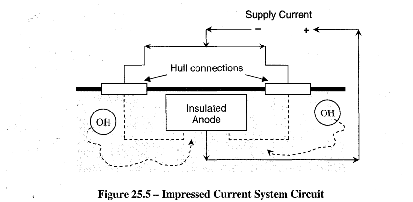
Figure 25.4 - Impressed Current System
Generally there are two subsystems comprising a Forward Controller Power Unit and an Aft Controller Power Unit. One central remote monitoring unit is normally shared between the two units; it is normally located in the engine control room. This unit helps to maintain the daily log of readings and also caters to housing the alarm circuits in case of any abnormalities in the system. Some monitoring facilities in the cathodic protection control cabinet / remote monitoring unit may facilitate the measurements of the following:
Reference Electrode Voltage (hull potential)
Amplifier output voltage
Total anode current
Individual anode current
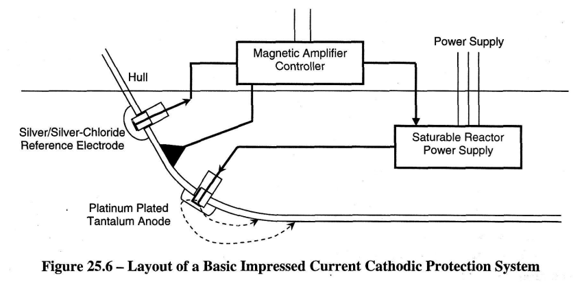
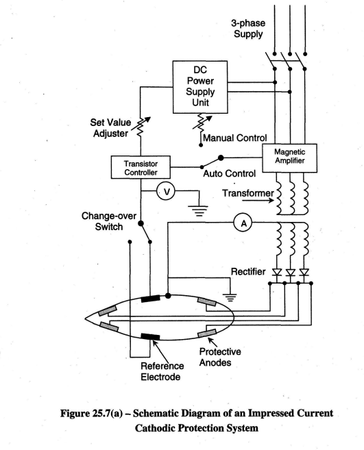
Electronic thyristor amplifiers or magnetic amplifiers may control the anode current. The schematic diagrams in Figures 25.6 and 25.7(a) are examples of this. The operation of a magnetic amplifier is explained in article 25.2.3 and is depicted in Figure 25.7(b)
The control equipment automatically monitors the magnitude of anode current required. This will vary with the ship's speed, water temperature and salinity, condition of paint work, etc. Typical anode current densities range from 10mA/m2 to 40mA/m2 for the protection of painted surfaces and 100 to 150mA/m2 for bare surfaces. The total controller current for a hull in good condition may be as low as 20A.
Maximum controller outputs in the automatic mode may be up to about 600A at 8V. Manual adjustments are also possible. Cathodic protection does not appear to deter molluscular growth on the ship's hull so a topcoat of anti-foul (poisonous) paint is still necessary.
As seen in Figure 25.5, the anode is insulated from the hull, electrical connection is via cable and ships side gland box. It may be made of lead or Platinised Titanium. With the lead anodes, the hydroxyl ions turn the surface of the lead to a rich brown colour (Pb02).
A d.c. voltage is applied to just overcome the natural galvanic voltage. If the current is allowed to become too great then the increased hydroxyl release causes sponginess and flaking of the paint
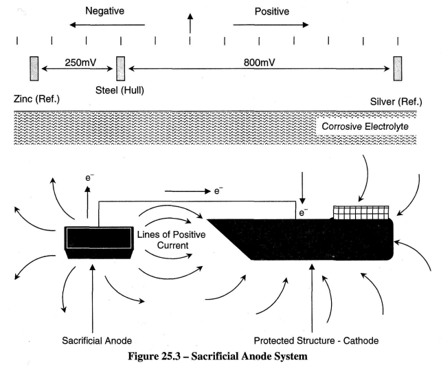
Referring to Figure 25.7(a), the cathodic system should make the hull 200mV more cathodic i.e. 200mV negatively charged. The system measures this by checking the hull voltage against an insulated reference anode which has a known value of galvanic voltage with the hull material.
Typically this may be Zinc which is normally at a voltage 450mV more negative than the hull, or silver which is 600 mV more positive than the hull. The Cathodic protection system will try to make the potential difference between the hull and the zinc reference anode 250 mV (Zinc anode 250mV more negative than the hull), and the silver anode 600mV (Silver anode 800mV more positive than the hull).
Measurements should be regularly logged, e.g. location, draught, water temperature, etc. Changes in underwater hull area, speed, water temperature / salinity and paint conditions cause the anode current to vary. The hull potential should, however, remain constant in a properly regulated system.
Although the reference electrodes and the monitoring facilities give a reasonable day-today check they only measure in the vicinity of the fitted electrodes. When the ship is moored singly or stopped at sea, voltage reading can be taken between portable silver or zinc test electrode and the ship's hull. This portable electrode is lowered 6-8 feet below the water surface, as close as possible to the hull at a specified position around the ship.
Check the manufacturer's instructions regarding the storage and setting up of the portable electrode. Some have to be immersed in a plastic bucket of seawater for about 4 hours before the hull test. With the cathodic protection system switched on and working normally, the voltage measured between the hull and a silver / silver chloride portable electrode should be 750-850mV using a high-resistance multimeter (e.g. an AVO meter of the analog or digital type), the electrode being positive with respect to the hull.'
When the ship is dry-docked, ensure that the main anodes and reference electrodes are covered with paper tape to prevent contamination by paint.
In order to ensure that the rudder, propeller and stabiliser fins receive the same degree of cathodic protection as the hull, it is necessary to electrically bond these to the hull. The rudderstock may be bonded by a wire braid linking the top of the stock to the deck head directly about it. Carbon brushes in contact with slip rings on the main propulsion shaft effectively bond the shaft to the hull. A periodic inspection of such earthing is worthwhile as the brushes wear away and may occasionally stick in their brush holders; this also ensures efficient bonding. A second set of brushes, insulated from the earth, can be used to connect a mV meter that monitors the shaft's potential.
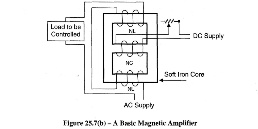
Magnetic Amplifiers
Sometimes referred to as "transductors" magnetic amplifiers came into use because of the limitations of thermionic valves and the rotary amplifier. A schematic diagram of the circuit is shown in Figure 25.7(b).
By applying a controlled d.c. current to coil NC the flux density can be increased until the core is saturated. At this point the device is highly sensitive and a small change in the d.c. current, say a signal from a sensor/transducer, will immediately vary a relatively large load in the winding NL. Such amplifiers are robust, have no moving parts and require no routine attention. The power amplification per cycle of a single-stage magnetic amplifier is in the region of 100 to 1.
A reduction in weight and size and an improved rate of response may be obtained by increasing the frequency of supply but a fairly delicate design compromise is necessary; the optimum would appear to be about 400Hz. The additional expense of a special 400Hz alternator could be justified only where many magnetic amplifiers are required.
The magnetic amplifier shares with the amplidyne, a comparative freedom from electrical interference. On the other hand, the magnetic amplifier is not inherently reversible, and if required for a reversing operation it usually has to be duplicated in a push-pull arrangement of some kind. This requires that each amplifier is at least double the rating of the field winding constituting the load. This tends to make the magnetic amplifier expensive for such applications. A basic magnetic amplifier is depicted in Figure 25.7(b).
Routine Checks
S Record the output current and all voltages, including the reference electrode voltage, on a daily basis.
S Check and clean the propeller shaft's slip ring and brushes every week.
S Inspect the rudder stock earth strap once a month.
S Carry out other inspections / maintenance as directed in the ship's manuals.
Dangers to be avoided
#; Considerations should be given to spark hazards created by introduction of electric currents into structures situated in hazardous atmosphere.
# Any secondary structure residing in the same electrolyte may receive and discharge the cathodic protection dc current by acting as an alternative low resistance path. Corrosion will be accelerated on the secondary structure at any point where current is discharged to the electrolyte. This phenomenon is called as "interaction".
# Interaction is minimized by careful design of the cathodic protection system. Therefore where there are chances of interaction to take place we use SACP systems because they are less prone to interaction.