

4F27E
.pdfTechnical Service Information
109 
12
110
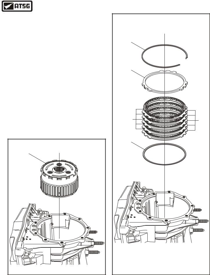
END COVER
12 DIRECT CLUTCH SEALING RINGS (2 REQUIRED).
109DIRECT CLUTCH HUB BEARING RACE (SELECTIVE).
110REVERSE CLUTCH SEALING RINGS (2 REQUIRED).
Copyright © 2004 ATSG
Figure 27
DIRECT CLUTCH HOUSING |
NUMBER 1 THRUST BEARING |
Copyright © 2004 ATSG |
Figure 28
INTERNAL COMPONENTS (CONT'D)
12.Remove the direct clutch hub bearing race from the end cover, as shown in Figure 27.
Note: This race is selective to set transaxle end play so do not lose it.
13.Remove and discard the direct and reverse clutch sealing rings, as shown in Figure 27.
14.Set the end cover aside for the component rebuild section.
15.Remove the direct clutch number 1 thrust bearing, as shown in Figure 28.
16.Remove the direct/reverse clutch housing from transaxle, as shown in Figure 29.
17.Set the direct/reverse clutch housing aside for the component rebuild section.
Continued on Page 23
DIRECT CLUTCH |
HOUSING |
Copyright © 2004 ATSG |
Figure 29
22 |
AUTOMATIC TRANSMISSION SERVICE GROUP |
|
Technical Service Information
INTERNAL COMPONENTS (CONT'D)
18.Remove the planetary gearset from transaxle by lifting straight up, as shown in Figure 30.
19.Set the planetary gearset aside for component rebuild section.
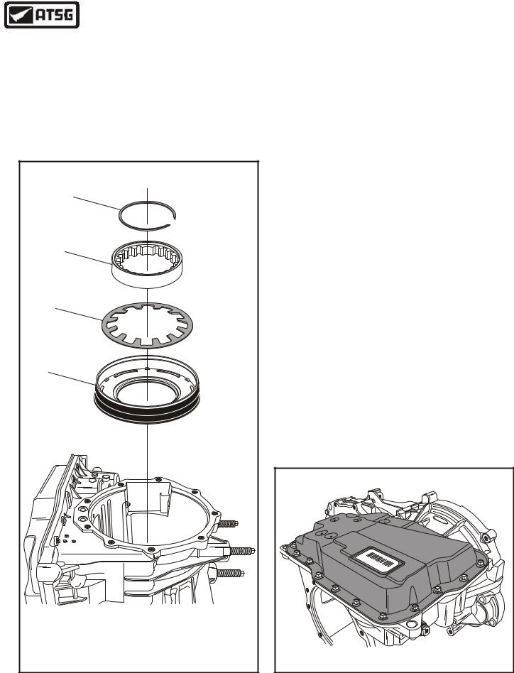
20.Remove the low/reverse clutch backing plate snap ring, as shown in Figure 31.
21.Remove the low/reverse clutch backing plate, as shown in Figure 31.
22.Remove the low/reverse clutch plates, as shown in Figure 31.
Note: This clutch pack consists of five steel plates and five friction plates.
23.Remove the low/reverse clutch cushion "cone" plate, as shown in Figure 31.
Continued on Page 24
PLANETARY GEARSET |
ASSEMBLY |
Copyright © 2004 ATSG |
|
1 |
|
|
2 |
|
|
3 |
4 |
|
|
|
|
5 |
|
1 |
LOW/REVERSE CLUTCH BACKING PLATE "SELECTIVE" SNAP RING. |
|
2 |
LOW/REVERSE CLUTCH BACKING PLATE. |
|
3 |
LOW/REVERSE CLUTCH FRICTION PLATES (5 REQUIRED). |
|
4 |
LOW/REVERSE CLUTCH STEEL PLATES (5 REQUIRED). |
|
5 |
LOW/REVERSE CLUTCH CUSHION PLATE (CONE). |
|
|
Copyright © 2004 ATSG |
|
Figure 30 |
Figure 31 |
AUTOMATIC TRANSMISSION SERVICE GROUP |
23 |
|
Technical Service Information
INTERNAL COMPONENTS (CONT'D)
24.Remove the low sprag inner race retaining snap ring, as shown in Figure 32.
25.Remove the low sprag inner race, as shown in Figure 32.
Note: The sprag inner race also serves as the bellville spring retainer.
|
6 |
|
7 |
|
8 |
|
9 |
6 |
LOW SPRAG INNER RACE RETAINING SNAP RING. |
7 |
LOW SPRAG INNER RACE. |
8 |
LOW/REVERSE CLUTCH PISTON "BELLVILLE" RETURN SPRING. |
9 |
LOW/REVERSE CLUTCH PISTON. |
|
Copyright © 2004 ATSG |
Figure 32
26.Remove the low/reverse clutch piston bellville return spring, as shown in Figure 32.
27.Remove the low/reverse clutch molded piston, as shown in Figure 32.
28.Rotate the transaxle so that the bottom pan is facing up, as shown in Figure 33.
Note: This is best accomplished by removing from fixture and standing on bell housing and top studs on flat surface work bench.
Continued on Page 25
|
|
|
|
dro |
|
|
|
|
F |
|
|
|
6 |
|
|
|
|
790 |
|
|
|
|
2 |
|
F |
|
|
439 |
|
|
|
01 |
F |
|
B |
|
|
B |
|
|
4P |
|
P4S |
|
|
|
X |
||
|
|
S |
|
|
|
|
|
X |
|
|
|
|
AVA |
|
|
|
|
P |
|
|
|
|
|
Copyright © 2004 ATSG |
Figure 33
24 |
AUTOMATIC TRANSMISSION SERVICE GROUP |
|
Technical Service Information
INTERNAL COMPONENTS (CONT'D)
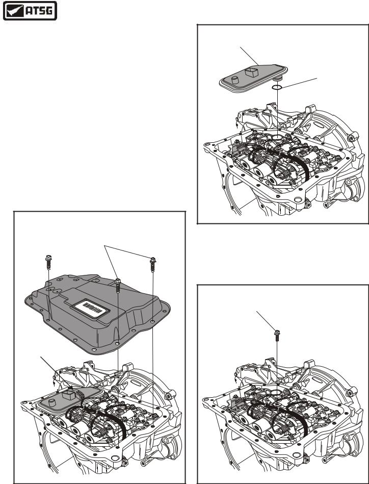
29.Remove the 20 bottom pan bolts, as shown in Figure 34, and remove bottom pan.
30.Remove TFT Sensor from filter and lay to one side (See Figure 34).
31.Remove the fluid filter by pulling straight up, as shown in Figure 35.
Note: Discard filter and "O" ring.
32.Remove the solenoid harness ground wire bolt from the valve body, as shown in Figure 36.
Note: Remove the ground wire and screw the bolt back into valve body to prevent loss.
Continued on Page 26
|
|
|
PAN BOLTS |
|
|
(20 REQUIRED) |
|||
|
|
96 |
|
|
|
|
70 |
|
|
|
|
|
24 |
|
F |
|
|
|
39 |
|
|
|
10 |
|
|
|
|
BF |
|
B |
|
|
4P |
|
|
P4 |
|
|
XS |
|
S |
|
|
|
|
|
X |
A |
V |
|
|
|
||
|
|
|
PA |
|
TEMP |
|
|
|
|
SENSOR |
|
|
|
|
|
|
|
|
dro |
|
|
|
|
F |
|
|
|
|
Copyright © 2004 ATSG |
FLUID |
FILTER |
FLUID FILTER |
"O" RING |
dro |
F |
Copyright © 2004 ATSG |
Figure 35
SOLENOID GROUND |
WIRE BOLT |
dro |
F |
Copyright © 2004 ATSG |
Figure 34 |
Figure 36 |
AUTOMATIC TRANSMISSION SERVICE GROUP |
25 |
|
Technical Service Information
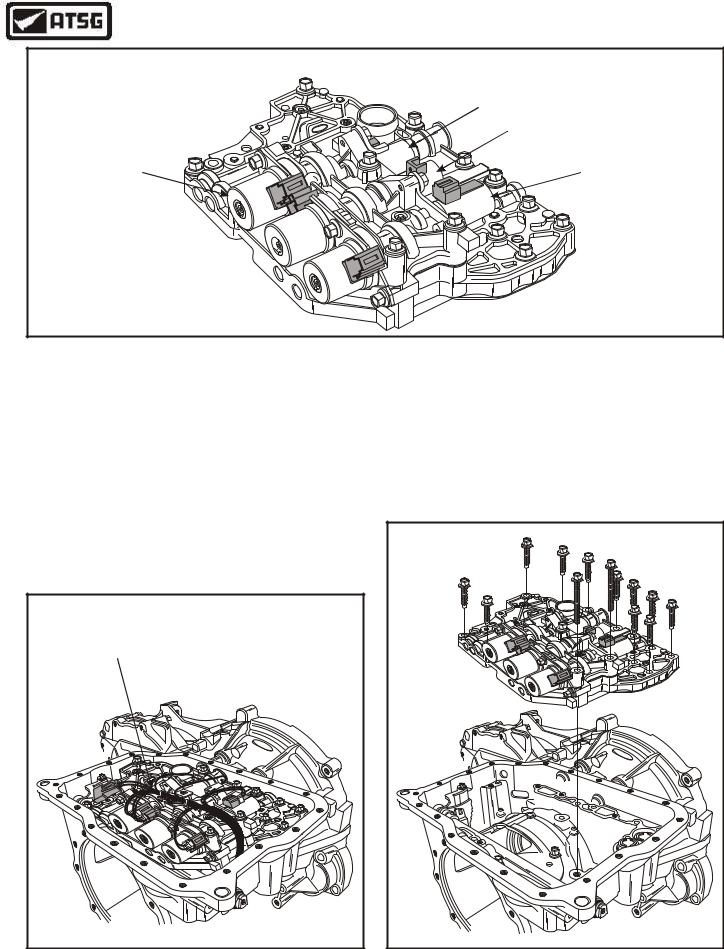
INTERNAL HARNESS CONNECTOR COLOR IDENTIFICATION
SHIFT SOLENOID "D"
CONNECTOR "BLUE"
SHIFT SOLENOID "E"
CONNECTOR "GREEN" 


SHIFT SOLENOID "B" CONNECTOR "BLACK"
ord F
L
B
N
G
B
N
SHIFT SOLENOID "A"
CONNECTOR "WHITE"
EPC SOLENOID
 CONNECTOR "BLACK"
SHIFT SOLENOID "C"
CONNECTOR "WHITE" 

Copyright © 2004 ATSG
Figure 37
INTERNAL COMPONENTS (CONT'D)
33.Remove individual solenoid internal harness connectors from their respective solenoids, as shown in Figure 38, and lay internal harness off to one side.
Note: It is necessary to note the color of the internal harness connectors so they can be connected in the same positions. Connector color letters are cast into the solenoid body, as shown in Figure 37.
INTERNAL |
WIRE HARNESS |
dro |
F |
Copyright © 2004 ATSG |
Figure 38
34.Remove the 13 valve body retaining bolts, as shown in Figure 39, and remove valve body.
35.Set the valve body aside for the component rebuild section.
Continued on Page 27
d |
For |
L |
B |
N |
G |
B |
N |
dro |
F |
Copyright © 2004 ATSG |
Figure 39
26 |
AUTOMATIC TRANSMISSION SERVICE GROUP |
|
Technical Service Information
Copyright © 2004 ATSG |
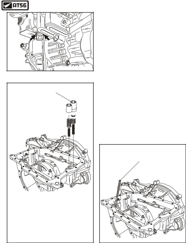
INTERNAL COMPONENTS (CONT'D)
36.Squeeze the tabs on the side of the internal harness case connector, and remove internal harness from transaxle (See Figure 40).
37.Remove the neutral/drive and 1-2 accumulator pistons and springs, as shown in Figure 41.
Note: Each of the two accumulators have two springs. All four springs are different sizes. Spring specifications are listed in Figure 41.
38.Remove the manual lever shaft retaining roll pin using a drift punch and small hammer, as shown in Figure 42.
Figure 40 |
Continued on Page 28 |
|
1-2 ACCUMULATOR
NEUTRAL/DRIVE 
 ACCUMULATOR


droF
NEUTRAL-DRIVE OUTER
FREE LENGTH ---------- |
2.945" |
DIAMETER --------------- |
.824" |
WIRE DIAMETER --------- |
.089" |
COLOR I.D. ------------- |
NONE |
NEUTRAL-DRIVE INNER |
|
FREE LENGTH ---------- |
2.145" |
DIAMETER --------------- |
.610" |
WIRE DIAMETER --------- |
.094" |
COLOR I.D. ------------- |
NONE |
|
|
|
|
|
|
|
|
|
|
|
|
|
|
|
|
|
|
|
|
1-2 OUTER |
|
||
FREE LENGTH ---------- |
2.655" |
||
DIAMETER --------------- |
.824" |
||
WIRE DIAMETER --------- |
.137" |
||
COLOR I.D. ----------- |
YELLOW |
||
1-2 INNER |
|
||
FREE LENGTH ---------- |
2.655" |
||
DIAMETER --------------- |
.510" |
||
WIRE DIAMETER --------- |
.087" |
||
COLOR I.D. ----------- |
YELLOW |
||
Copyright © 2004 ATSG
DRIFT |
PUNCH |
dro |
F |
Copyright © 2004 ATSG |
Figure 41 |
Figure 42 |
AUTOMATIC TRANSMISSION SERVICE GROUP |
27 |
|
Technical Service Information
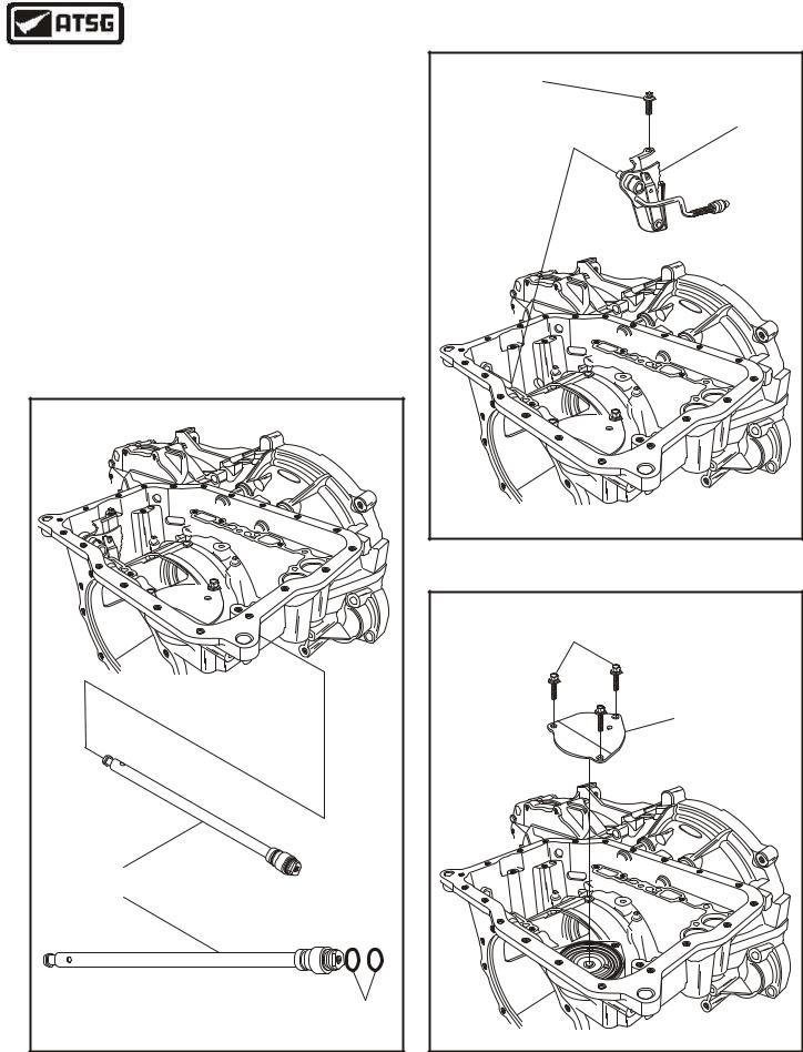
INTERNAL COMPONENTS (CONT'D)
39.Remove the manual lever shaft from transaxle case, as shown in Figure 43.
40.Remove and discard the two manual lever shaft "O" ring seals, as shown in Figure 43.
41.Remove the internal control lever retaining bolt, as shown in Figure 44, and remove the internal control lever assembly.
42.Remove intermediate/overdrive servo cover, as shown in Figure 45.
Caution: The 2-4 band servo cover is spring loaded. The bolts should be loosened evenly until cover is unloaded, then remove bolts.
Continued on Page 29
dro |
F |
MANUAL LEVER |
SHAFT |
"O" RING |
SEALS |
Copyright © 2004 ATSG |
RETAINING |
BOLT |
INTERNAL CONTROL |
LEVER ASSEMBLY |
dro |
F |
Copyright © 2004 ATSG |
Figure 44
RETAINING |
BOLTS |
INTERMEDIATE/OVERDRIVE |
SERVO COVER |
dro |
F |
Copyright © 2004 ATSG |
Figure 43 |
Figure 45 |
28 |
AUTOMATIC TRANSMISSION SERVICE GROUP |
|
Technical Service Information
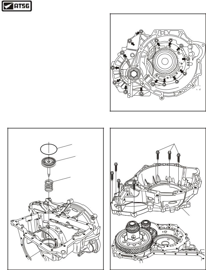
INTERNAL COMPONENTS (CONT'D)
43.Remove and discard the servo cover "O" ring seal, as shown in Figure 46.
44.Remove the 2-4 servo piston, as shown in Figure 46.
45.Remove the 2-4 servo piston return spring, as shown in Figure 46.
46.Install the transaxle back into the bench fixture and rotate transaxle so that the bell housing
is facing up, as shown in Figure 47.
Caution: Transaxle must be installed back into bench fixture to prevent damage and/or
personal injury.
48.Remove the 15 converter housing to case bolts, as shown in Figure 47, and remove converter housing from case, as shown in Figure 48.
Continued on Page 30
Copyright © 2004 ATSG |
2-4 SERVO COVER |
"O" RING SEAL |
2-4 SERVO |
PISTON |
2-4 SERVO PISTON |
RETURN SPRING |
dro |
F |
Copyright © 2004 ATSG |
Figure 46
Figure 47
CONVERTER HOUSING |
TO CASE BOLTS |
(15 REQUIRED) |
F |
dro |
CONVERTER |
HOUSING |
Copyright © 2004 ATSG |
Figure 48
AUTOMATIC TRANSMISSION SERVICE GROUP |
29 |
|
Technical Service Information
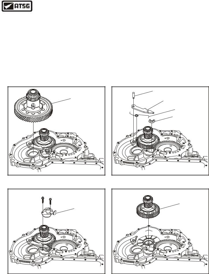
INTERNAL COMPONENTS (CONT'D)
49.Remove the differential assembly, as shown in Figure 49, and set aside for component rebuild.
50.Remove the two parking pawl cover retaining bolts, as shown in Figure 50, and remove the parking pawl cover.
51.Release the park pawl spring from the parking pawl using a pair of pliers.
52.Remove the parking pawl pivot pin using a pencil magnet (See Figure 51).
53.Remove the parking pawl from case, as shown in Figure 51.
54.Remove parking pawl spring and abutment, as shown in Figure 51.
55.Remove the transfer shaft assembly, as shown in Figure 52.
56.Set the transfer shaft assembly aside for the component rebuild section.
Continued on Page 31
DIFFERENTIAL |
ASSEMBLY |
Copyright © 2004 ATSG |
Figure 49
PARKING PAWL |
COVER |
Copyright © 2004 ATSG |
Figure 50
PIVOT PIN |
PARKING |
PAWL |
PARKING PAWL |
SPRING |
PARKING PAWL |
ABUTMENT |
Copyright © 2004 ATSG |
Figure 51
TRANSFER SHAFT |
ASSEMBLY |
Copyright © 2004 ATSG |
Figure 52
30 |
AUTOMATIC TRANSMISSION SERVICE GROUP |
|

Technical Service Information
INTERNAL COMPONENTS (CONT'D)
57.This now leaves nothing in the case except the final drive input gear, as shown in Figure 53.
Note: This gear involves an exceptional amount of set-up time if it is removed, as it involves a "Crush" sleeve (See Figure 53). Our recommendation is "Not" to remove it , if there is no problem with the bearings.
"If there are problems with the bearings", refer to the complete bearing and shim set-up in the Component Rebuild section.
Transaxle Disassembly Complete
FINAL DRIVE |
INPUT GEAR |
FINAL DRIVE |
INPUT GEAR |
Copyright © 2004 ATSG |
Figure 53
COMPONENT REBUILD SECTION
OIL PUMP ASSEMBLY
1.Disassemble the oil pump assembly using Figure 55 as a guide.
2.Remove and discard the two stator shaft seal rings, as shown in Figure 55.
3.Clean all oil pump parts thoroughly and dry with compressed air.
4.Inspect all oil pump parts thoroughly for any wear and/or damage. Replace as necessary.
5.Place oil pump body on a flat work surface, as shown in Figure 54, and replace bushing using the proper bushing driver, as necessary.
Continued on Page 33
PUMP BODY |
BUSHING |
Copyright © 2004 ATSG |
Figure 54
AUTOMATIC TRANSMISSION SERVICE GROUP |
31 |
|