

4F27E
.pdfTechnical Service Information
COMPONENT REBUILD SECTION
BEARING REPLACEMENT AND SET-UP (CONT'D)
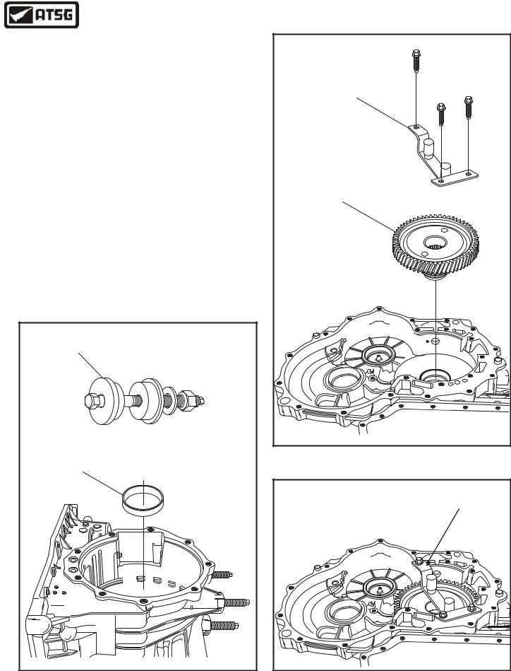
8.Rotate the transaxle 180 degrees and loosen, but do not remove the three bolts retaining the holding tool, as shown in Figure 113.
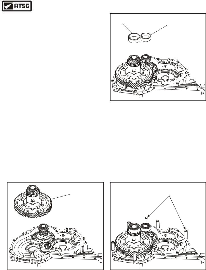
9.Rotate the transaxle 180 degrees again, and gently tap on the final drive input gear shaft to loosen it from the bearing.
10.Remove the rear bearing from transaxle, as shown in Figure 114.
11.Rotate the transaxle 180 degrees again, remove final drive input gear holding tool, as shown in Figure 115.
12.Remove the final drive input gear from the transaxle case, as shown in Figure 115
Continued on Page 63
LOOSEN BOLTS 3 ONLY |
DO NOT REMOVE |
Copyright © 2004 ATSG |
Figure 113
FINAL DRIVE INPUT |
GEAR REAR BEARING |
Copyright © 2004 ATSG |
Figure 114
FINAL DRIVE INPUT |
GEAR ASSEMBLY |
Copyright © 2004 ATSG |
Figure 115
62 |
AUTOMATIC TRANSMISSION SERVICE GROUP |
|

Technical Service Information
CRUSH SLEEVE
FINAL DRIVE INPUT
GEAR FRONT BEARING
Copyright © 2004 ATSG
Figure 116
INSTALL NEW
CRUSH SLEEVE
Copyright © 2004 ATSG
Figure 117
COMPONENT REBUILD SECTION
BEARING REPLACEMENT AND SET-UP (CONT'D)
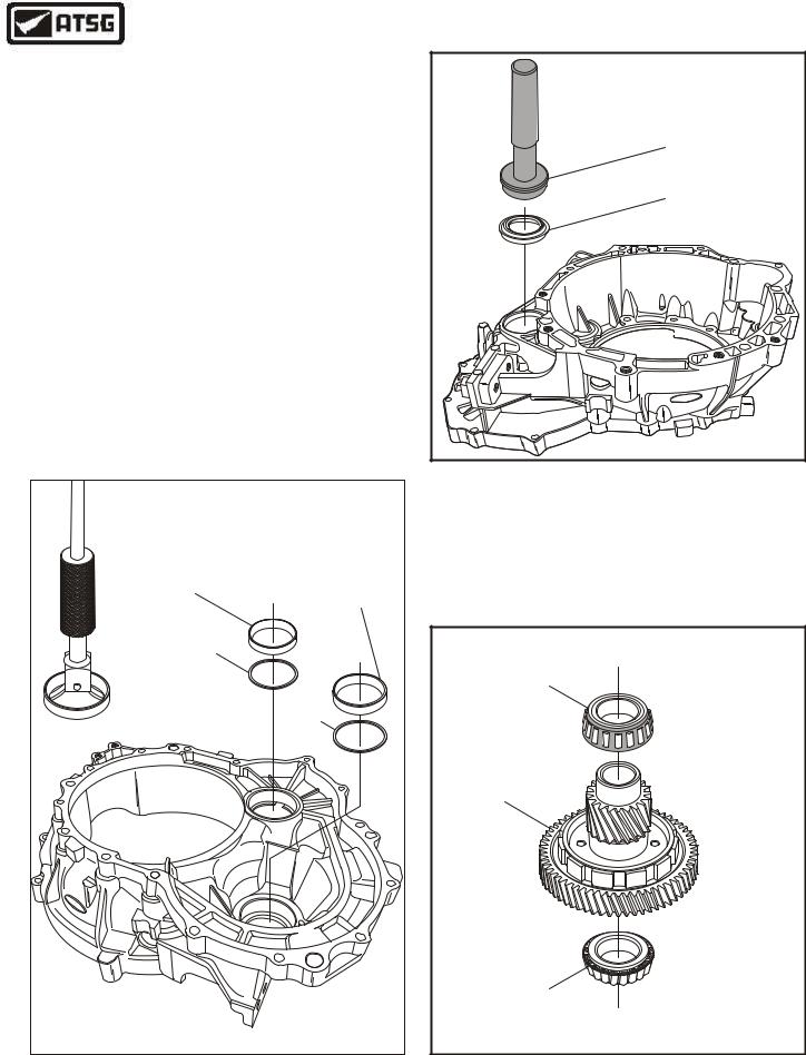
13.Remove and discard the final drive input gear crush sleeve, as shown in Figure 116.
14.Remove and replace the tapered roller bearing, as shown in Figure 116, using the proper tools and hydraulic press to remove and replace.
15.After new tapered roller bearing is pressed on,
install a new crush sleeve (See Figure 117).
18.Set final drive input gear assembly aside for the moment, while we prepare to install it.
19.Remove all three bearing races from transaxle case using a slide hammer with proper adapter, as shown in Figure 118.
20.Install new final drive input bearing cup using the proper driver, as shown in Figure 118.
Continued on Page 64
REMOVE WITH |
SLIDE HAMMER |
HANDLE |
205-153 |
BEARING CUP ADAPTER |
308-163 |
FINAL DRIVE INPUT |
GEAR BEARING CUP |
Copyright © 2004 ATSG |
Figure 118
AUTOMATIC TRANSMISSION SERVICE GROUP |
63 |
|

Technical Service Information
HANDLE |
REMOVE WITH |
205-153 |
SLIDE HAMMER |
BEARING CUP |
|
ADAPTER 307-418 |
|
TRANSFER SHAFT |
|
GEAR BEARING CUP |
|
LUBE OIL |
|
FUNNEL |
|
|
Copyright © 2004 ATSG |
COMPONENT REBUILD SECTION
BEARING REPLACEMENT AND SET-UP (CONT'D)
21.Install lube oil funnel into transfer shaft cup bore in case, as shown in Figure 119.
22.Install new transfer shaft bearing cup into case, using proper driver, as shown in Figure 119.
23.Install new differential case bearing cup into case using proper driver (See Figure 120).
24.Rotate transaxle case in fixture 180 degrees, as shown in Figure 121.
25.Remove rear final drive input gear bearing cup using slide hammer, as shown in Figure 121.
Continued on Page 65
Figure 119
HANDLE |
205-153 |
BEARING CUP |
ADAPTER 205-118 |
DIFFERENTIAL CASE |
BEARING CUP |
Copyright © 2004 ATSG |
Figure 120
REMOVE WITH |
SLIDE HAMMER |
FINAL DRIVE INPUT |
GEAR BEARING CUP |
Copyright © 2004 ATSG |
Figure 121
64 |
AUTOMATIC TRANSMISSION SERVICE GROUP |
|
Technical Service Information
COMPONENT REBUILD SECTION
BEARING REPLACEMENT AND SET-UP (CONT'D)
26.Install new final drive input gear bearing cup using the installer, as shown in Figure 122.
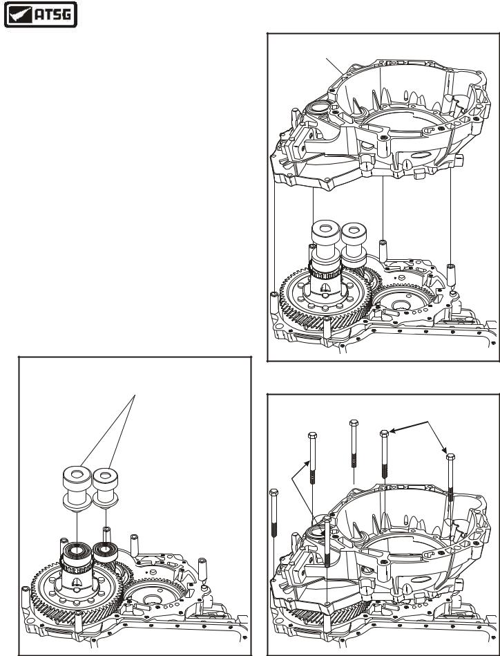
27.Rotate transaxle case in fixture 180 degrees, as shown in Figure 123.
28.Install the final drive input gear assembly into transaxle case, as shown in Figure 123.
29.Install the final drive input gear holding tool 307-413, as shown in Figure 123, and tighten all three bolts.
30.Lock the final drive input gear into position using the holding tool (See Figure 124).
Continued on Page 66
FINAL DRIVE INPUT GEAR |
CUP INSTALLER 205-024 |
FINAL DRIVE INPUT |
GEAR BEARING CUP |
Copyright © 2004 ATSG |
FINAL DRIVE INPUT GEAR |
HOLDING TOOL 307-413 |
FINAL DRIVE INPUT |
GEAR ASSEMBLY |
Copyright © 2004 ATSG |
Figure 123
FINAL DRIVE INPUT GEAR |
HOLDING TOOL 307-413 |
Copyright © 2004 ATSG |
Figure 122 |
Figure 124 |
AUTOMATIC TRANSMISSION SERVICE GROUP |
65 |
|
Technical Service Information
COMPONENT REBUILD SECTION
BEARING REPLACEMENT AND SET-UP (CONT'D)
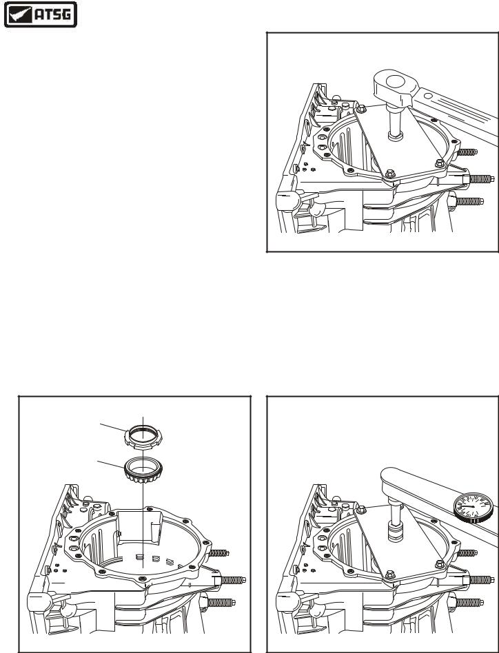
31.Rotate the transaxle 180 degrees again so that end cover side is facing up (See Figure 125).
32.Install the new final drive input gear bearing cone, as shown in Figure 125.
33.Install a new final drive input bearing retainer nut, as shown in Figure 125.
Note: Requires a new nut as it will once again have to be "staked".
34.Install the final drive input nut socket 307-414 and wrenching plate (See Figure 126).
Note: A very high tightening torque is required to crush the new collapsible sleeve for correct bearing preload.
35.Torque the final drive input bearing nut to, 450 N•m (332 ft.lb.), as shown in Figure 126.
36.Measure the rotating torque with inch pound torque wrench, as shown in Figure 127, which should be 0.3-0.6 N•m (2.65 to 5.30 in.lb.).
Note: If rotating torque is too low, tighten the bearing retainer nut and check the rotating torque again.
Note: If the rotating torque is too high, you must install another new crush sleeve, tighten the bearing retainer nut and check rotating torque again.
TORQUE NUT TO |
450 N•M (332 FT.LB.) |
Copyright © 2004 ATSG |
Figure 126
37.If the rotating torque is within specification, remove the tools, and stake the bearing retainer nut against the flats on final drive input gear shaft using a hammer and punch.
Continued on Page 67
RETAINING NUT |
FINAL DRIVE INPUT |
GEAR BEARING CONE |
Copyright © 2004 ATSG |
Figure 125
ROTATING TORQUE SHOULD BE |
|
|
|
0.3-0.6 N•m |
(2.65 - 5.30 IN.LB.) |
|
|
|
6 |
7 |
8 |
|
|
||
|
5 |
|
9 |
|
4 |
|
0 |
|
|
1 |
|
|
3 |
|
|
|
2 |
1 |
0 |
|
|
|
|
|
Copyright © 2004 ATSG |
||
Figure 127
66 |
AUTOMATIC TRANSMISSION SERVICE GROUP |
|
Technical Service Information
COMPONENT REBUILD SECTION
BEARING REPLACEMENT AND SET-UP (CONT'D)
38.Remove the differential bearing cup using the slide hammer, as shown in Figure 128.
39.Remove the differential bearing cup selective shim, as shown in Figure 128.
Note: Do not install new differential bearing cup at this time. It will be installed later.
40.Remove the transfer shaft bearing cup using the slide hammer, as shown in Figure 128.
41.Remove the transfer shaft bearing cup selective shim, as shown in Figure 128.
Note: Do not install the new transfer shaft bearing cup at this time. It will be installed later.
42.Turn the empty bell housing over and install a new right hand axle seal using the proper seal installer, as shown in Figure 129.
Note: The left hand axle seal in case uses the same installer and can be installed now.
SEAL INSTALLER |
307-256 |
RIGHT HAND |
AXLE SEAL |
F |
dor |
Copyright © 2004 ATSG |
|
|
Figure 129 |
USE SLIDE HAMMER |
|
|
TO REMOVE |
|
43. Remove and replace the two transfer shaft |
|
|
|
|
|
bearing cones, as shown in Figure 130, using |
TRANSFER SHAFT |
the proper adapters and a hydraulic press. |
|
BEARING CUP |
DIFFERENTIAL |
Continued on Page 68 |
|
BEARING CUP |
|
SELECTIVE |
|
|
SHIM |
|
|
|
|
TRANSFER SHAFT |
|
|
BEARING CONE |
|
SELECTIVE |
|
|
SHIM |
|
|
|
TRANSFER SHAFT |
|
|
AND GEAR |
Fo |
|
|
rd |
|
|
|
|
TRANSFER SHAFT |
|
|
BEARING CONE |
|
Copyright © 2004 ATSG |
Copyright © 2004 ATSG |
Figure 128 |
Figure 130 |
AUTOMATIC TRANSMISSION SERVICE GROUP |
67 |
|
Technical Service Information
COMPONENT REBUILD SECTION
BEARING REPLACEMENT AND SET-UP (CONT'D)
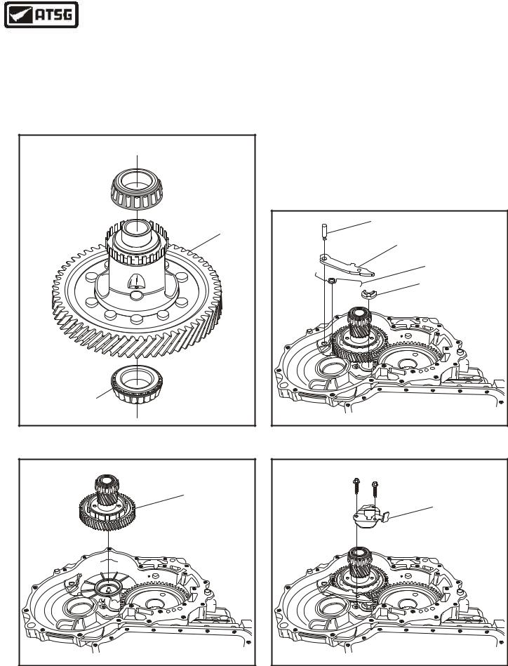
43.Remove and replace the two differential case bearing cones, as shown in Figure 131, using the proper adapters and a hydraulic press.
44.Install completed transfer shaft assembly into transaxle case, as shown in Figure 132.
DIFFERENTIAL HOUSING
BEARING CONE 
DIFFERENTIAL
ASSEMBLY
DIFFERENTIAL HOUSING
BEARING CONE
Copyright © 2004 ATSG
Figure 131
TRANSFER SHAFT |
ASSEMBLY |
Copyright © 2004 ATSG |
Figure 132
45.Install parking pawl spring into the case and over the case casting dowel (See Figure 133).
46.Install the parking pawl abutment, as shown in Figure 133.
47.Install the parking pawl into case and install the pivot pin, as shown in Figure 133.
48.Install the park pawl spring into hole in parking pawl using a pair of pliers (See Figure 133).
49.Install the parking pawl cover, as shown in Figure 134, install retaining bolts and torque to 13 N•m (10 ft.lb.)
Continued on Page 69
PIVOT PIN |
PARKING |
PAWL |
PARKING PAWL |
SPRING |
PARKING PAWL |
ABUTMENT |
Copyright © 2004 ATSG |
Figure 133
PARKING PAWL |
COVER |
Copyright © 2004 ATSG |
Figure 134
68 |
AUTOMATIC TRANSMISSION SERVICE GROUP |
|
Technical Service Information
COMPONENT REBUILD SECTION
BEARING REPLACEMENT AND SET-UP (CONT'D)
50.Install the completed differential assembly into the transaxle case, as shown in Figure 135.
51.Install the new differential bearing cup onto the differential bearing cone, as shown in Figure 136.
52.Install the new transfer shaft bearing cup onto the transfer shaft bearing cone, as shown in Figure 136.
Note: For the next step you will need the Shim Selection Tool Set (308-164) and the Differential and Transfer Gear Bearing Shim Gauge (307-417).
53.Place the six spacers from the Shim Selection Tool Set (308-164) in the positions that are shown in Figure 137.
DIFFERENTIAL |
TRANSFER SHAFT |
|
BEARING CUP |
||
BEARING CUP |
||
|
||
|
Copyright © 2004 ATSG |
Figure 136
Continued on Page 70
DIFFERENTIAL |
ASSEMBLY |
Copyright © 2004 ATSG |
Figure 135
SPACERS FROM 308-164 SET |
6 REQUIRED IN POSITIONS SHOWN |
Copyright © 2004 ATSG |
Figure 137
AUTOMATIC TRANSMISSION SERVICE GROUP |
69 |
|
Technical Service Information
COMPONENT REBUILD SECTION
BEARING REPLACEMENT AND SET-UP (CONT'D)
54.Install differential case bearing shim selection gauge from 307-417 on the differential case bearing, as shown in Figure 138.
55.Install the transfer shaft bearing shim selection gauge from (307-417) on the transfer shaft bearing, as shown in Figure 138.
56.Place the converter housing carefully over the transaxle case, as shown in Figure 139.
57.Install two long bolts from the Shim Selection Tool Set (308-164) in the positions that are shown in Figure 140.
58.Install four shorter bolts from Shim Selection Tool Set (308-164) in the remaining four positions.
59.Torque these six bolts to 5 N•m (45 in.lb.).
Continued on Page 71
DIFFERENTIAL/TRANSFER GEAR |
BEARING SHIM GAUGE 307-417 |
Copyright © 2004 ATSG |
CONVERTER |
HOUSING |
F |
dor |
Copyright © 2004 ATSG |
Figure 139
FOUR |
SHORTER BOLTS |
TWO |
LONG |
BOLTS |
F |
dor |
Copyright © 2004 ATSG |
Figure 138 |
Figure 140 |
70 |
AUTOMATIC TRANSMISSION SERVICE GROUP |
|

Technical Service Information
COMPONENT REBUILD SECTION
BEARING REPLACEMENT AND SET-UP (CONT'D)
60.Remove the six bolts and remove the converter housing from the transaxle (See Figure 140A).
61.Measure the depth of the plunger on the special tool (307-417) for the differential case bearing, using a depth micrometer (See Figure 141).
Note: Record this dimension for differential.
62.Measure the depth of the plunger on the special tool (307-417) for the transfer shaft bearing, using a depth micrometer (See Figure 142).
Note: Record dimension for transfer shaft.
63.Remove all special tools from transaxle.
Continued on Page 72
CONVERTER |
HOUSING |
F |
dro |
Copyright © 2004 ATSG |
DIFFERENTIAL MEASUREMENT |
||||
DEPTH |
|
|
|
|
MICROMETER |
|
|
|
|
S t arrett |
|
|
||
8 |
9 |
0 |
|
|
Figure 141 |
|
|
||
TRANSFER SHAFT MEASUREMENT |
||||
DEPTH |
|
|
||
MICROMETER |
|
|
||
|
|
S t arrett |
||
|
|
8 |
9 |
0 |
Figure 142 |
|
|
||
Figure 140A
AUTOMATIC TRANSMISSION SERVICE GROUP |
71 |
|