

4F27E
.pdfTechnical Service Information
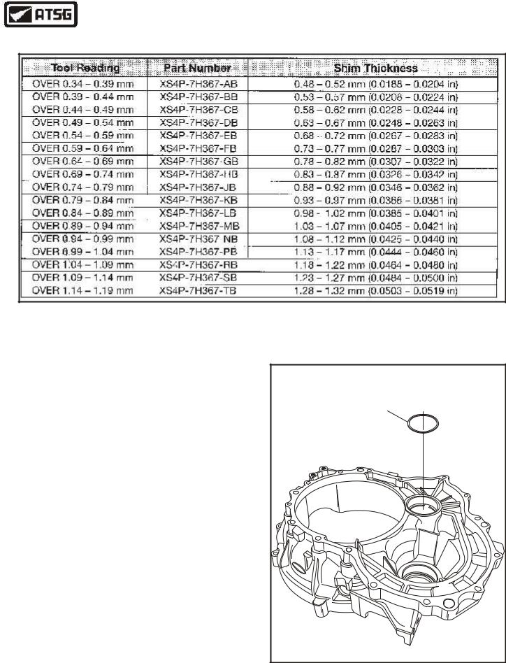
DIFFERENTIAL BEARING SHIM - SELECTION CHART
Figure 143
COMPONENT REBUILD SECTION
BEARING REPLACEMENT AND SET-UP (CONT'D)
64.Using the dimension that you recorded from differential tool, select the correct differential bearing shim from the chart in Figure 143.
65.Install the selected shim for the differential bearing into the converter housing, as shown in Figure 144.
Continued on Page 73
SELECTED |
DIFFERENTIAL |
BEARING SHIM |
Fo |
rd |
Copyright © 2004 ATSG |
Figure 144
72 |
AUTOMATIC TRANSMISSION SERVICE GROUP |
|
Technical Service Information
TRANSFER SHAFT BEARING SHIM - SELECTION CHART
Figure 145
COMPONENT REBUILD SECTION
BEARING REPLACEMENT AND SET-UP (CONT'D)
66.Using the dimension that you recorded from transfer shaft tool, select correct transfer shaft bearing shim from the chart in Figure 145.
67.Install the selected shim for the transfer shaft bearing into the converter housing, as shown in Figure 146.
Continued on Page 74
SELECTED |
TRANSFER SHAFT |
BEARING SHIM |
Fo |
rd |
Copyright © 2004 ATSG |
Figure 146
AUTOMATIC TRANSMISSION SERVICE GROUP |
73 |
|
Technical Service Information
COMPONENT REBUILD SECTION
BEARING REPLACEMENT AND SET-UP (CONT'D)
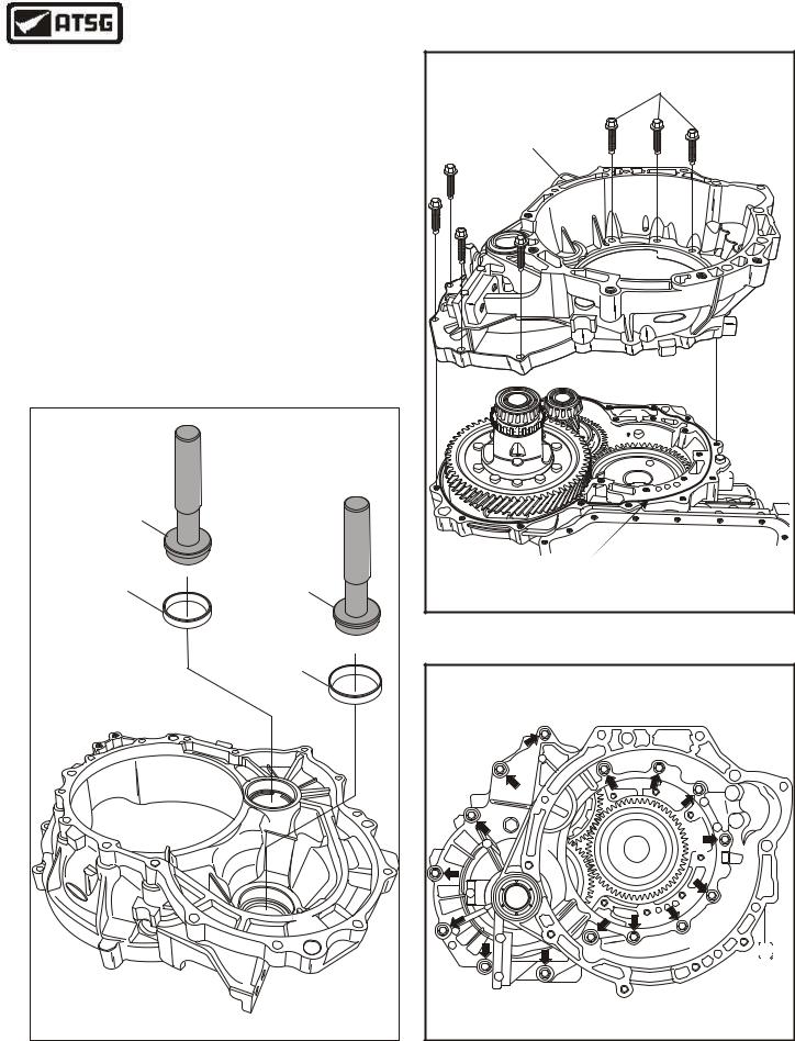
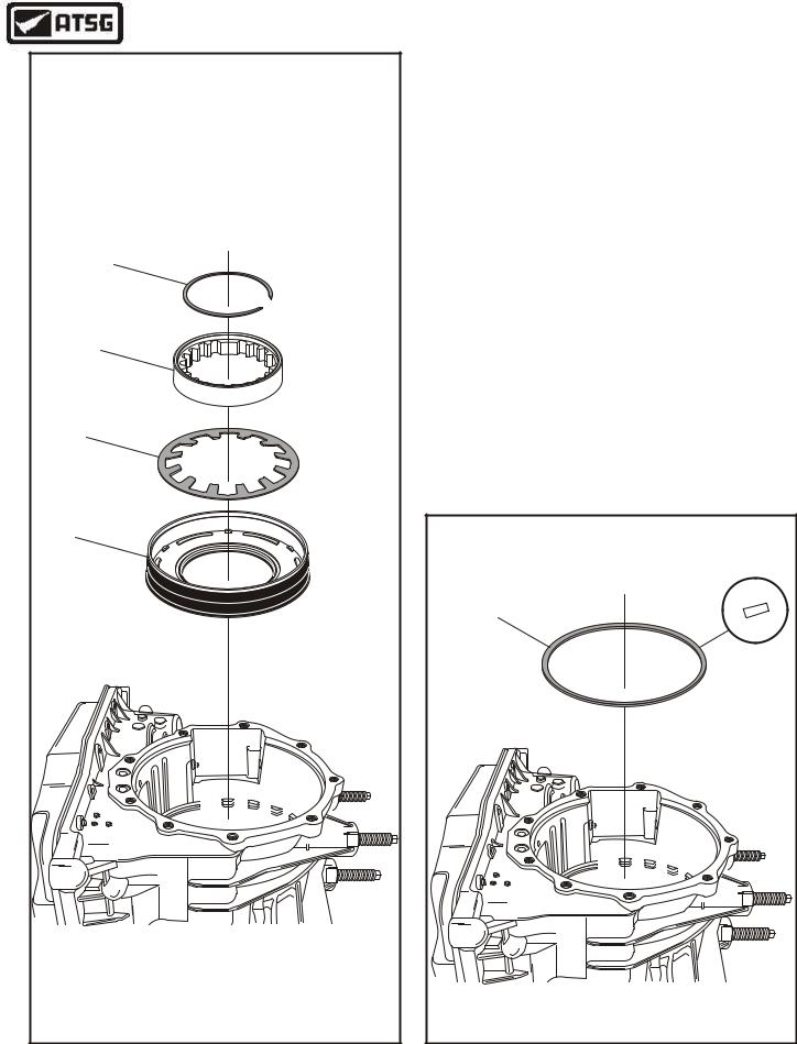
68.Install the differential bearing cup using the proper adapter, as shown in Figure 147.
69.Install the transfer shaft bearing cup using the proper adapter, as shown in Figure 147.
70.Apply a one-millimeter (1 mm) thick bead of Ultra Silicone Sealant (or equivalent) on the transaxle case sealing area for the converter housing, as shown in Figure 148.
71.Install the completed converter housing on the transaxle case, as shown in Figure 148, and ensure it is over alignment dowels.
72.Install 15 converter housing to case bolts in the locations shown in Figure 149.
Continued on Page 75
ADAPTER |
|
|
307-418 |
|
|
TRANSFER SHAFT |
ADAPTER |
|
205-118 |
||
BEARING CUP |
||
|
||
|
DIFFERENTIAL |
|
|
BEARING CUP |
|
Fo |
|
|
rd |
|
|
|
Copyright © 2004 ATSG |
CONVERTER HOUSING BOLTS |
(15 REQUIRED) |
COMPLETED |
CONVERTER |
HOUSING |
F |
dor |
1 MM BEAD OF |
SILICONE |
Copyright © 2004 ATSG |
Figure 148
Copyright © 2004 ATSG |
Figure 147 |
Figure 149 |
74 |
AUTOMATIC TRANSMISSION SERVICE GROUP |
|
Technical Service Information |
||
|
COMPONENT REBUILD SECTION |
|
|
BEARING REPLACEMENT AND SET-UP (CONT'D) |
|
|
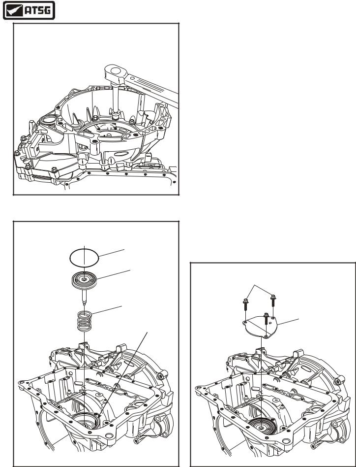
72. Torque all 15 converter housing to case bolts |
|
|
to 22 N•m (16 ft.lb.) (See Figure 150). |
|
|
TRANSMISSION ASSEMBLY |
|
|
INTERNAL COMPONENTS |
|
|
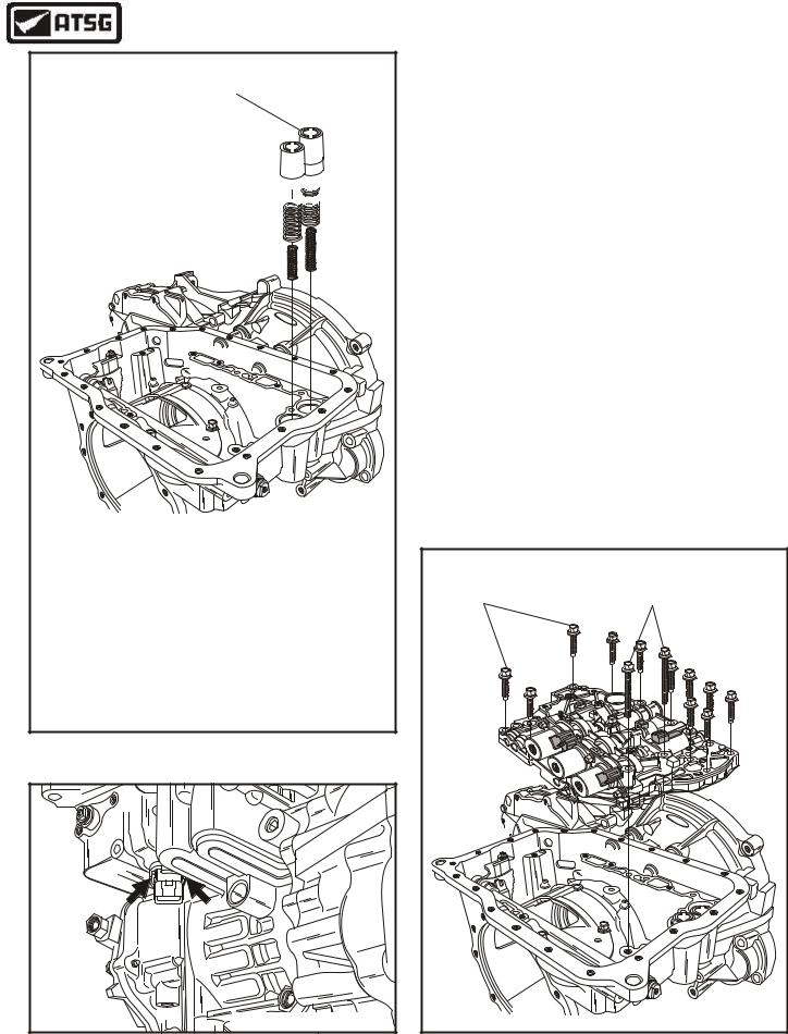
1. Install 2-4 servo piston return spring into the |
|
|
2-4 servo bore, as shown in Figure 151. |
|
|
2. Install a new 2-4 servo piston assembly into the |
|
F |
2-4 servo bore, as shown in Figure 151. |
|
dro |
||
|
||
|
3. Install new 2-4 servo cover "O" ring seal into |
|
|
the groove in case, as shown in Figure 151. |
|
|
4. Install the 2-4 servo cover and three retaining |
|
Copyright © 2004 ATSG |
bolts, as shown in Figure 152. |
|
Figure 150 |
Note: The 3 bolts must be loosely installed, |
|
then tightened in sequence to compress the |
||
|
||
|
2-4 servo spring evenly. |
|
2-4 SERVO COVER |
"O" RING SEAL |
2-4 SERVO |
PISTON |
2-4 SERVO PISTON |
RETURN SPRING |
GROOVE |
dro |
F |
Copyright © 2004 ATSG |
5.Torque the three 2-4 servo bolts evenly to 13 N•m (10 ft.lb.).
Continued on Page 76
RETAINING |
BOLTS |
INTERMEDIATE/OVERDRIVE |
SERVO COVER |
dro |
F |
Copyright © 2004 ATSG |
Figure 151 |
Figure 152 |
AUTOMATIC TRANSMISSION SERVICE GROUP |
75 |
|
Technical Service Information
RETAINING |
BOLT |
INTERNAL CONTROL |
LEVER ASSEMBLY |
dro |
F |
Copyright © 2004 ATSG |
TRANSMISSION ASSEMBLY
INTERNAL COMPONENTS (CONT'D)
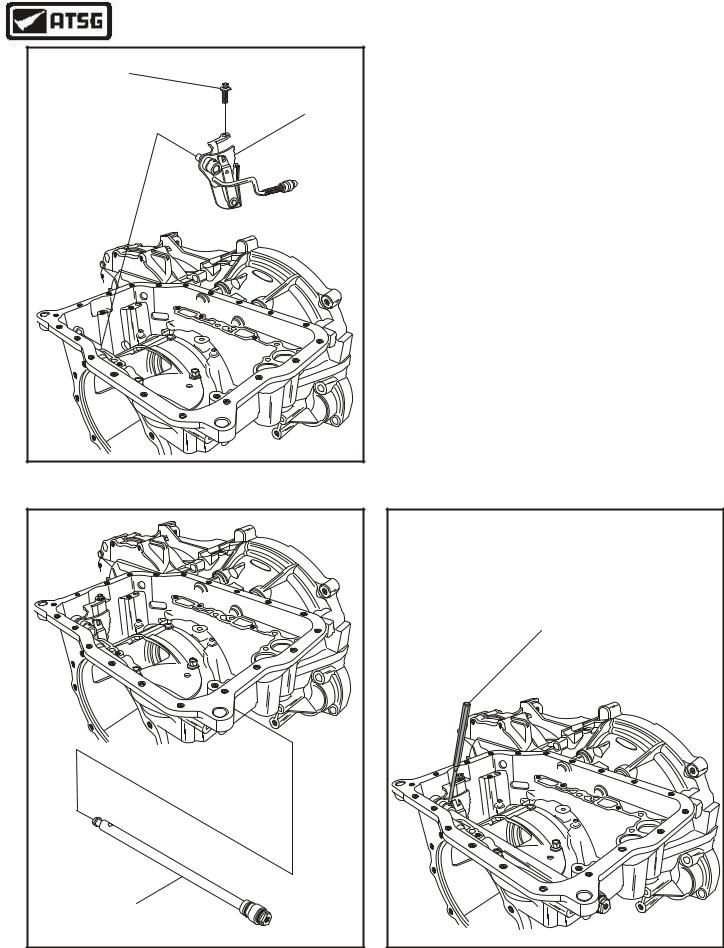
6.Install the internal control lever assembly into transaxle case, as shown in Figure 153, and ensure that parking rod is engaged properly with the parking pawl.
7.Install the retaining bolt loosely at this time.
8.Lubricate the manual lever shaft "O" ring seals and install the manual lever shaft, as shown in Figure 154.
9.Align the manual lever shaft inside of internal control lever assembly and install new roll pin, as shown in Figure 155.
10.Check the operation of the manual linkage and ensure that park rod engages the parking pawl without binding. Torque the internal control lever bolt to 13 N•m (10 ft.lb.).
Continued on Page 77
Figure 153
dro |
F |
MANUAL LEVER |
SHAFT |
Copyright © 2004 ATSG |
Figure 154
DRIFT |
PUNCH |
dro |
F |
Copyright © 2004 ATSG |
Figure 155
76 |
AUTOMATIC TRANSMISSION SERVICE GROUP |
|
Technical Service Information
1-2 ACCUMULATOR
NEUTRAL/DRIVE 
 ACCUMULATOR


droF
NEUTRAL-DRIVE OUTER
FREE LENGTH ---------- |
2.945" |
DIAMETER --------------- |
.824" |
WIRE DIAMETER --------- |
.089" |
COLOR I.D. ------------- |
NONE |
NEUTRAL-DRIVE INNER |
|
FREE LENGTH ---------- |
2.145" |
DIAMETER --------------- |
.610" |
WIRE DIAMETER --------- |
.094" |
COLOR I.D. ------------- |
NONE |
|
|
|
|
|
|
|
|
|
|
|
|
|
|
|
|
|
|
|
|
1-2 OUTER |
|
||
FREE LENGTH ---------- |
2.655" |
||
DIAMETER --------------- |
.824" |
||
WIRE DIAMETER --------- |
.137" |
||
COLOR I.D. ----------- |
YELLOW |
||
1-2 INNER |
|
||
FREE LENGTH ---------- |
2.655" |
||
DIAMETER --------------- |
.510" |
||
WIRE DIAMETER --------- |
.087" |
||
COLOR I.D. ----------- |
YELLOW |
||
Copyright © 2004 ATSG
Figure 156
Copyright © 2004 ATSG |
Figure 157
TRANSMISSION ASSEMBLY
INTERNAL COMPONENTS (CONT'D)
11.Install the 1-2 accumulator piston and springs in the bore closest to the converter housing, as shown in Figure 156.
12.Install the neutral/drive accumulator piston and springs in case bore, as shown in Figure 156.
Note: Each of the two accumulators have two springs. All four springs are different sizes. Spring specifications are listed in Figure 156. The two accumulator pistons are the same.
13.Install a new "O" ring on the connector of the internal wire harness, lubricate and install the internal wire harness through the case bore until the tabs lock it into position, as shown in Figure 157.
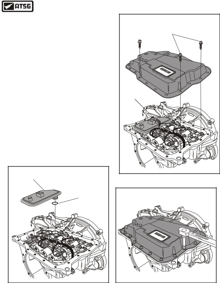
14.Install the pre-assembled valve body assembly onto transaxle case, as shown in Figure 158.
Note: Ensure that manual valve is engaged with internal lever and V.B. is over dowels.
15.Install eleven 40 mm length bolts and two
71 mm length bolts in the positions that are shown in Figure 158.
Continued on Page 78
40 MM LENGTH |
71 MM LENGTH |
VALVE BODY BOLTS |
VALVE BODY BOLTS |
(11 REQUIRED) |
(2 REQUIRED) |
|
d |
|
For |
|
L |
|
B |
|
N |
|
G |
|
B |
|
N |
|
dro |
|
F |
|
Copyright © 2004 ATSG |
Figure 158
AUTOMATIC TRANSMISSION SERVICE GROUP |
77 |
|

Technical Service Information
INTERNAL HARNESS CONNECTOR COLOR IDENTIFICATION
ord F
SHIFT SOLENOID "D" |
L |
|
HARNESS CONNECTOR |
||
B |
||
|
||
IS "BLUE" |
|
N
G
SHIFT SOLENOID "E"
HARNESS CONNECTOR

IS "GREEN"
SHIFT SOLENOID "C"
HARNESS CONNECTOR 

IS "WHITE"
B N
SHIFT SOLENOID "B"
HARNESS CONNECTOR
IS "BLACK"
SHIFT SOLENOID "A"
HARNESS CONNECTOR
IS "WHITE"
EPC SOLENOID
HARNESS CONNECTOR
IS "BLACK"
B = BLACK
G = GREEN
L = BLUE
N = NEUT OR WHITE
Copyright © 2004 ATSG
Figure 159
TRANSMISSION ASSEMBLY
INTERNAL COMPONENTS (CONT'D)
16.Torque all of the valve body to case bolts to 9 N•m (80 in.lb.), as shown in Figure 160.
17.Install the individual solenoid internal harness connectors to their respective solenoids, as shown in Figure 159 and 161.
18.Install the solenoid ground wire bolt through the wire terminal, as shown in Figure 161, and torque to 10 N•m (89 in.lb.).
CAUTION: It is mandatory that the internal wire harness connectors be connected to the proper solenoids. Figure 159 provides you the internal harness connector colors that should be connected to the individual solenoids. The color of the connector that should be connected to that solenoid is also cast into the valve body, as shown in Figure 159.
Continued on Page 79
dro |
F |
Copyright © 2004 ATSG |
Figure 160
INTERNAL |
SOLENOID GROUND |
WIRE BOLT |
|
WIRE HARNESS |
|
|
dro |
|
F |
|
Copyright © 2004 ATSG |
Figure 161
78 |
AUTOMATIC TRANSMISSION SERVICE GROUP |
|
Technical Service Information
TRANSMISSION ASSEMBLY
INTERNAL COMPONENTS (CONT'D)
19.Install a new "O" ring onto the new filter, as shown in Figure 162, and lubricate with small amount of Trans-Jel®.
20.Install the fluid filter assembly into the bore of the valve body, as shown in Figure 162.
21.Install the fluid temperature sensor by snapping it into position on the filter (See Figure 163).
22.Apply a one-and-a-half (1.5 mm) bead of Loctite® 5699 sealant (or equivalent) to the transaxle pan surface.
23.Check the filter, solenoid connections, ground wire bolt tight, linkage engage park pawl, one more time before we install the pan.
24.Install the transaxle fluid pan, as shown in Figure 163.
25.Install the twenty fluid pan bolts and torque to 7 N•m (62 in.lb.), as shown in Figure 164.
Continued on Page 80
FLUID |
FILTER |
FLUID FILTER |
"O" RING |
dro |
F |
Copyright © 2004 ATSG |
|
|
PAN BOLTS |
|
|
(20 REQUIRED) |
||
|
96 |
|
|
|
70 |
|
|
|
|
24 |
|
BF |
|
39 |
|
|
|
10 |
|
|
|
F |
|
|
|
B |
|
XS4P |
A |
XS4P |
|
|
|||
|
|
A |
|
|
|
V |
|
|
|
|
P |
TEMP |
|
|
|
SENSOR |
|
|
|
|
|
|
dro |
|
|
|
F |
|
|
|
Copyright © 2004 ATSG |
Figure 163
|
TORQUE TO |
|
7 N•M (62 IN.LB.) |
||
|
|
dro |
|
|
F |
|
9 |
|
|
760 |
|
|
2 |
|
F |
349 |
|
10 |
BF |
|
B |
|
P |
|
XS4P |
S4X |
|
|
|
|
A |
|
|
A |
|
|
V |
|
|
P |
|
|
|
Copyright © 2004 ATSG |
Figure 162 |
Figure 164 |
AUTOMATIC TRANSMISSION SERVICE GROUP |
79 |
|
Technical Service Information
|
6 |
|
7 |
|
8 |
|
9 |
6 |
LOW SPRAG INNER RACE RETAINING SNAP RING. |
7 |
LOW SPRAG INNER RACE. |
8 |
LOW/REVERSE CLUTCH PISTON "BELLVILLE" RETURN SPRING. |
9 |
LOW/REVERSE CLUTCH PISTON. |
|
Copyright © 2004 ATSG |
INTERNAL COMPONENTS (CONT'D)
26.Rotate transaxle in fixture so that end cover surface is facing up, as shown in Figure 165.
27.Lubricate and install the low/reverse clutch molded piston, as shown in Figure 165.
28.Install the "Bellville" low/reverse clutch piston return spring, as shown in Figure 165.
29.Install the low sprag inner race, as shown in Figure 165.
Note: The low sprag inner race also serves as bellville return spring retainer.
30.Install the low sprag race retaining snap ring, as shown in Figure 165, and ensure that it is fully seated in the groove.
31.Install the low/reverse clutch cushion (cone) spring on top of the low reverse clutch piston in the direction shown in Figure 166.
Continued on Page 81
5 |
5 LOW/REVERSE CLUTCH CUSHION PLATE (CONE). |
Copyright © 2004 ATSG |
Figure 165 |
Figure 166 |
80 |
AUTOMATIC TRANSMISSION SERVICE GROUP |
|
Technical Service Information
TRANSMISSION ASSEMBLY
INTERNAL COMPONENTS (CONT'D)
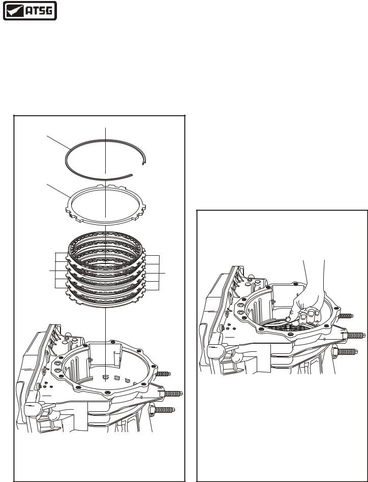
32.Install the low/reverse clutch plates beginning with a steel plate and alternating with frictions until you have installed five of each, as shown in Figure 167.
Note: Friction plates should be soaked in Mercon® V fluid for 15 minutes before
|
installation. |
|
|
1 |
|
|
2 |
|
|
3 |
4 |
|
|
|
1 |
LOW/REVERSE CLUTCH BACKING PLATE "SELECTIVE" SNAP RING. |
|
2 |
LOW/REVERSE CLUTCH BACKING PLATE. |
|
3 |
LOW/REVERSE CLUTCH FRICTION PLATES (5 REQUIRED). |
|
4 |
LOW/REVERSE CLUTCH STEEL PLATES (5 REQUIRED). |
|
|
Copyright © 2004 ATSG |
|
Figure 167
33.Install the low/reverse clutch backing plate, as shown in Figure 167.
34.Install the selective low/reverse clutch backing plate snap ring, as shown in Figure 167.
35.Measure the clearance between the snap ring and the backing plate with a feeler gauge, as shown in Figure 168.
36.The low/reverse clutch clearance should be 2.2 to 2.5 mm (.087" to .098"), as shown in Figure 168.
37.Change the selective snap ring as necessary to obtain the correct specification, as shown in Figure 168.
Continued on Page 82
LOW/REVERSE CLUTCH CLEARANCE |
2.2 - 2.5 MM (.087" - .098") |
Selective Thickness Snap Rings Available |
1.75 to 1.85 mm (.069" to .073") |
1.95 to 2.05 mm (.077" to .081") |
2.15 to 2.25 mm (.085" to .089") |
2.35 to 2.45 mm (.093" to .097") |
2.55 to 2.65 mm (.100" to .104") |
2.75 to 2.85 mm (.108" to .112") |
2.95 to 3.05 mm (.116" to .120") |
Copyright © 2004 ATSG |
Figure 168
AUTOMATIC TRANSMISSION SERVICE GROUP |
81 |
|