

4F27E
.pdfTechnical Service Information
PLANETARY GEARSET |
ASSEMBLY |
Copyright © 2004 ATSG |
TRANSMISSION ASSEMBLY
INTERNAL COMPONENTS (CONT'D)
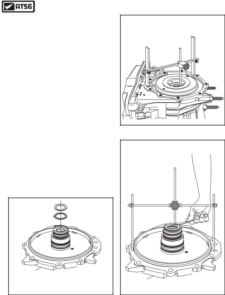
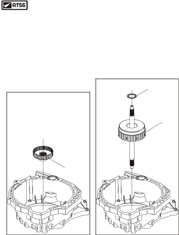
38.Install the pre-assembled planetary gearset, as shown in Figure 169, by rotating in a counterclockwise direction and ensure that it is fully seated over low sprag inner race.
Note: Must engage splines into input gear, splines on low/reverse frictions, and sprag onto inner race.
39.After installation, check for proper rotation of sprag assembly. Gearset should freewheel in a counter-clockwise direction and lock in the clockwise direction, as shown in Figure 170.
40.Install the pre-assembled direct/reverse clutch housing, as shown in Figure 171, by rotating into position.
Continued on Page 83
Figure 169 |
|
|
PLANETARY GEARSET SHOULD FREEWHEEL |
DIRECT/REVERSE |
|
COUNTER-CLOCKWISE AND LOCK |
||
CLUTCH HOUSING |
||
CLOCKWISE AFTER INSTALLATION |
|
|
IN THE TRANSAXLE CASE |
|
|
FREEWHEEL |
|
|
Copyright © 2004 ATSG |
Copyright © 2004 ATSG |
|
Figure 170 |
Figure 171 |
82 |
AUTOMATIC TRANSMISSION SERVICE GROUP |
|
Technical Service Information
TRANSMISSION ASSEMBLY
INTERNAL COMPONENTS (CONT'D)
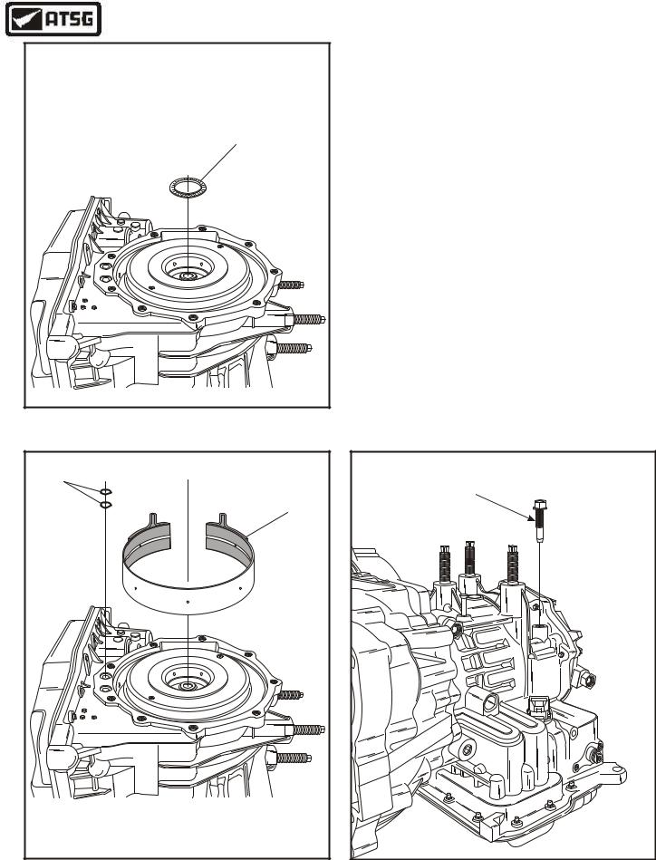
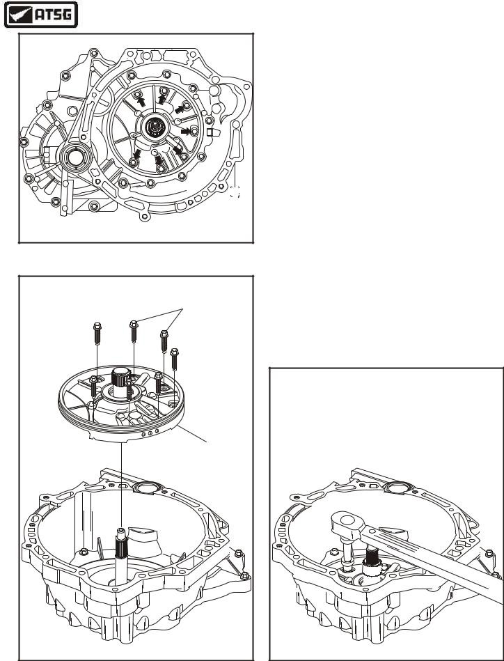
41.Install the direct clutch hub bearing race onto completed end cover, as shown in Figure 172.
Note: This is the selective race to set the transaxle end play.
42.Temporarily, install the direct clutch bearing with the needles facing down, as shown in Figure 172.
43.Install the "H" gauge onto the transaxle, as shown in Figure 173, adjust the center stem so that it rests on direct clutch housing bearing surface and tighten locking screw.
44.Turn the "H" gauge over and set on top of the end cover with selective and bearing in place, as shown in Figure 174.
45.Measure between the stem of "H" gauge and the bearing surface, as shown in Figure 174, to check transaxle end play.
46.Transaxle end play should be ,009" to .019", as shown in Figure 174.
47.Change the selective bearing race as necessary to obtain specification. Refer to chart below for available direct clutch bearing races.
Part Number |
Race Thickness |
XS4Z-7G262-AB |
1.775-1.825 mm (.070" to .072") |
XS4Z-7G262-BB |
1.925-2.025 mm (.078" to .080") |
XS4Z-7G262-CB |
2.175-2.225 mm (.086" to .088") |
XS4Z-7G262-DB |
2.375-2.425 mm (.093" to .095") |
XS4Z-7G262-EB |
2.575-2.625 mm (.101" to .103") |
Continued on Page 84
108 
109 
COMPLETED
END COVER
108NUMBER 1, DIRECT CLUTCH HUB THRUST BEARING
109DIRECT CLUTCH HUB BEARING RACE (SELECTIVE).
Copyright © 2004 ATSG
Copyright © 2004 ATSG |
Figure 173
TRANSAXLE END PLAY SHOULD BE |
.009" TO .019" |
COMPLETED |
END COVER |
Copyright © 2004 ATSG |
Figure 172 |
Figure 174 |
AUTOMATIC TRANSMISSION SERVICE GROUP |
83 |
|
Technical Service Information
DIRECT CLUTCH HOUSING |
NUMBER 1 THRUST BEARING |
Copyright © 2004 ATSG |
Figure175 |
112 |
107 |
107 INTERMEDIATE/OVERDRIVE BAND ASSEMBLY.
112 END COVER TO CASE "O" RING SEALS (2 REQUIRED).
Copyright © 2004 ATSG
TRANSMISSION ASSEMBLY
INTERNAL COMPONENTS (CONT'D)
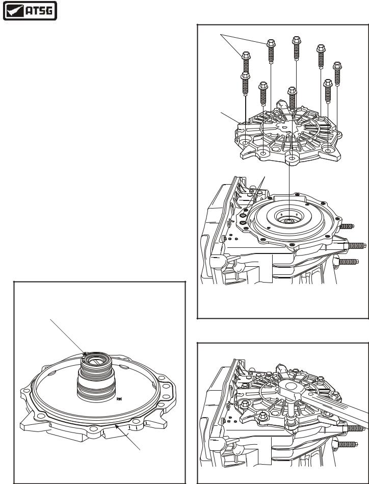
48.Install the number 1, direct clutch housing thrust bearing, with the needles facing up, as shown in Figure 175.
49.Install intermediate/overdrive band assembly, as shown in Figure 176.
50.Install two new end cover to case "O" ring seals into the pockets in the case, as shown in Figure 176, and retain with Trans-Jel®.
51.Temporarily install the 2-4 band anchor bolt, as shown in Figure 177.
Continued on Page 85
INTERMEDIATE/OVERDRIVE |
BAND ANCHOR BOLT |
(SELECTIVE) |
Copyright © 2004 ATSG |
Figure 176 |
Figure 177 |
84 |
AUTOMATIC TRANSMISSION SERVICE GROUP |
|
Technical Service Information
TRANSMISSION ASSEMBLY
INTERNAL COMPONENTS (CONT'D)
52.Install the selected bearing race onto the end cover and retain with Trans-Jel®, as shown in Figure 178.
53.Apply one-millimeter (1 mm) thick bead of Ultra Silicone Sealant (or equivalent) to the end cover surface, as shown in Figure 178.
54.Install the completed end cover onto transaxle, as shown in Figure 179.
Note: Ensure that "O" ring seals are still in place, as shown in Figure 179.
55.Install the nine end cover retaining bolts, as shown in Figure 179.
56.Torque the nine end cover retaining bolts to 22 N•m (16 ft.lb.), as shown in Figure 180.
Continued on Page 86
SELECTED |
BEARING RACE |
1 MM THICK BEAD |
OF SILICONE SEALANT |
Copyright © 2004 ATSG |
|
10 |
111 |
|
|
112 |
10 |
END COVER RETAINING BOLTS (9 REQUIRED). |
111 |
END COVER ASSEMBLY. |
112 |
END COVER TO CASE "O" RING SEALS (2 REQUIRED). |
|
Copyright © 2004 ATSG |
Figure 179
Copyright © 2004 ATSG |
Figure 178 |
Figure 180 |
AUTOMATIC TRANSMISSION SERVICE GROUP |
85 |
|
Technical Service Information
TRANSMISSION ASSEMBLY
INTERNAL COMPONENTS (CONT'D)
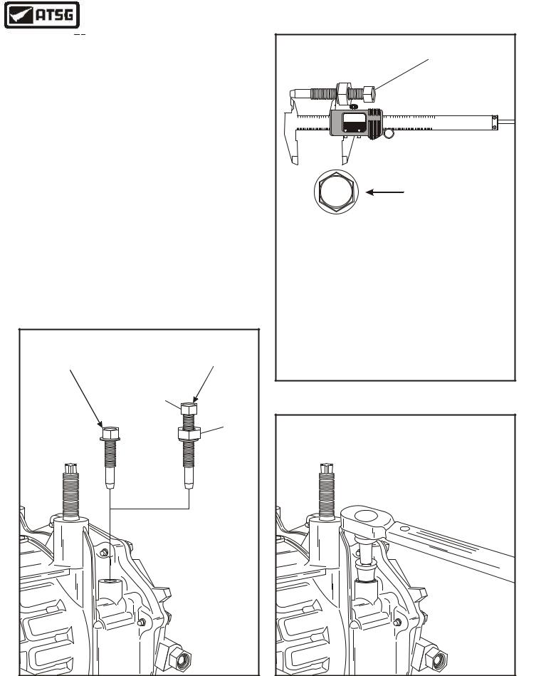
57.Remove the selective 2-4 band anchor bolt, as shown in Figure 181, and install the 307-416 Band Select Gauge.
58.Tighten the band select gauge bolt down to
5 N•m (45 in.lb.), and then back the bolt out exactly 3-1/2 turns.
59.While holding the band select gauge bolt in that position, lightly seat the nut and washer against the case.
60.Remove the band select gauge from the case, without changing the position of nut on bolt.
61.Measure the distance from end of the gauge to the washer, as shown in Figure 182.
62.Change the selective bolt as necessary to get the correct anchor using chart in Figure 182.
63.Install the selected band anchor bolt and torque to 45 N•m (33 ft.lb.), as shown in Figure 183.
Continued on Page 87
INTERMEDIATE/OVERDRIVE |
INTERMEDIATE/OVERDRIVE |
BAND ANCHOR BOLT |
BAND SELECT GAUGE |
(SELECTIVE) |
307-416 |
|
BOLT |
|
NUT |
Figure 181
INTERMEDIATE/OVERDRIVE
BAND SELECT GAUGE
307-416
|
|
|
|
|
|
1 |
|
|
|
|
|
2 |
|
IN |
01.457 3 |
|
|
|
|
|
|
4 |
|
|
|
|
|
|
|
|
|
5 |
|
|
|
|
|
|
6 |
|
in |
ELECTRONIC |
|||||
1 |
2 |
3 4 5 |
6 |
7 8 |
9 |
1 |
2 |
3 4 5 |
6 |
7 8 |
9 |
|
1 |
2 |
3 4 5 |
6 |
8 |
9 |
|
1 |
2 |
3 4 5 |
6 |
7 8 |
9 |
|
1 |
2 |
3 4 5 |
6 |
7 8 |
9 |
|
|
1 |
2 |
3 4 5 |
6 |
7 8 |
9 |
|
|
|||||
0 |
|
10 |
|
20 |
|
30 |
40 |
|
50 |
|
|
AUTO POWER-OFF |
|
|
80 |
|
90 |
|
100 |
|
|
110 |
|
120 |
|
130 |
|
140 |
|
150 |
|
|
DIGITAL C ALIPER |
||||||||||||||
|
|
|
|
|
|
|
|
60 |
|
70 |
|
|
|
|
|
|
|
|
|
|
|
mm |
|
||||||||||||||||||||||||
|
|
|
|
|
|
|
|
|
|
|
|
|
|
|
mm/in |
|
0 |
|
|
|
|
|
|
|
|
|
|
|
|
|
|
|
|
|
|
|
|
|
|
|
|
|
|
|
|
||
|
|
|
|
|
|
|
|
|
|
|
|
|
|
|
|
|
|
|
|
|
|
|
|
|
|
|
|
|
|
|
|
|
|
|
|
|
|
|
|
|
|
|
|
|
|
|
|
3 |
Identification |
|
|
Bolt Number |
Bolt Length |
1 |
36.0 mm (1.417") |
2 |
36.5 mm (1.437") |
3 |
37.0 mm (1.457") |
4 |
37.5 mm (1.476") |
5 |
38.0 mm (1.496") |
6 |
38.5 mm (1.516") |
7 |
39.0 mm (1.535") |
Copyright © 2004 ATSG
Figure 182
Figure 183
86 |
AUTOMATIC TRANSMISSION SERVICE GROUP |
|
Technical Service Information
TRANSMISSION ASSEMBLY
INTERNAL COMPONENTS (CONT'D)
64.Rotate the transaxle 180 degrees so that bell housing is facing up, as shown in Figure 184.
65.Install the forward clutch hub, as shown in Figure 184, by starting onto the splines and then tapping it down and over the cir-clip.
66.Install the completed forward clutch housing, as shown in Figure 185, by rotating back and forth until all clutch plates are engaged on the forward clutch hub.
67.Install the forward clutch housing to oil pump support thrust washer, as shown in Figure 185.
Continued on Page 88
FORWARD |
CLUTCH HUB |
Copyright © 2004 ATSG |
Figure 184
FORWARD CLUTCH |
THRUST WASHER |
FORWARD CLUTCH |
HOUSING ASSEMBLY |
Copyright © 2004 ATSG |
Figure 185
AUTOMATIC TRANSMISSION SERVICE GROUP |
87 |
|
Technical Service Information
Copyright © 2004 ATSG |
TRANSMISSION ASSEMBLY
INTERNAL COMPONENTS (CONT'D)
68.Install the completed oil pump assembly, as shown in Figure 187.
Note: Lubricate "O" ring seal with small amount of Trans-Jel® before installation.
69.Install the seven bolts that secure the oil pump to case in the locations shown in Figure 186.
Note: Gradually tighten each bolt equally to pull the oil pump into position.
70.Torque the oil pump to case retaining bolts to 22 N•m (16 ft.lb.), as shown in Figure 188.
Continued on Page 89
Figure 186
OIL PUMP BOLTS |
(7 REQUIRED) |
OIL PUMP |
ASSEMBLY |
Copyright © 2004 ATSG |
Figure 187
TORQUE BOLTS TO |
22 N•M (16 FT.LB.) |
Copyright © 2004 ATSG |
Figure 188
88 |
AUTOMATIC TRANSMISSION SERVICE GROUP |
|
Technical Service Information
TURBINE SHAFT |
RETAINING |
|
|
BOLT |
|
|
|
SPEED SENSOR |
|
|
|
|
|
|
|
INSTALL NEW |
|
|
|
"O" RING |
|
|
|
|
|
P |
|
|
X |
VAA |
|
|
S |
||
|
4P |
X |
|
|
|
B |
|
|
|
F |
S |
|
|
0 |
4 |
|
|
1 |
P |
|
|
9 |
- |
|
|
3 |
B |
|
|
4 |
F |
|
|
2 |
|
|
|
07 |
|
|
|
|
6 |
|
|
|
9 |
|
ord |
|
|
|
F |
|
|
|
Copyright © 2004 ATSG |
||
Figure 189
TRANSMISSION ASSEMBLY
EXTERNAL COMPONENTS
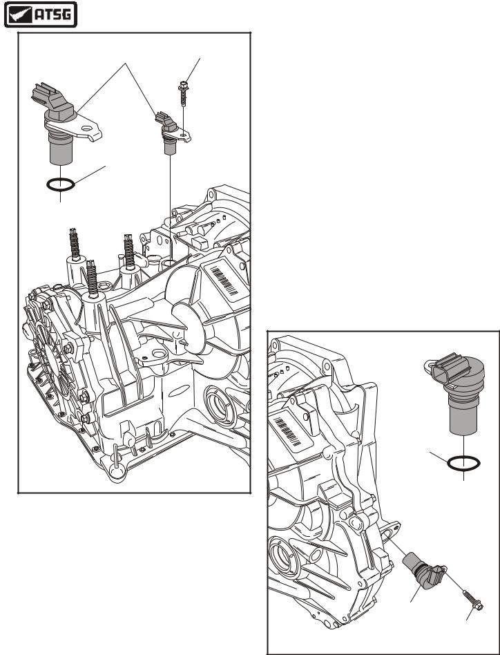
1.Install new "O" ring seal onto turbine shaft speed sensor, lubricate with small amount of Trans-Jel® and install into the case bore, as shown in Figure 189.
2.Install speed sensor retaining bolt and torque to 9 N•m (80 in.lb.) (See Figure 189).
3.Install new "O" ring onto output shaft speed sensor, lubricate with Trans-Jel® and install into the case bore, as shown in Figure 190.
4.Install speed sensor retaining bolt and torque to 9 N•m (80 in.lb.) (See Figure 190).
Continued on Page 90
X |
|
PVA |
|
S |
|
A |
|
4P |
X |
||
|
BF |
||
|
|
S4P |
|
|
0 |
||
|
|
1 |
|
|
|
9 |
- |
|
|
3 |
BF |
|
|
42 |
|
|
|
0 |
INSTALL NEW |
|
|
7 |
|
|
|
6 |
|
|
|
9 |
|
|
|
|
"O" RING |
|
|
|
OUTPUT SHAFT |
|
|
|
SPEED SENSOR |
|
|
|
RETAINING |
|
|
|
BOLT |
|
|
|
Copyright © 2004 ATSG |
Figure 190
AUTOMATIC TRANSMISSION SERVICE GROUP |
89 |
|

Technical Service Information
MANUAL SHAFT |
|
|
|
|
|
|
|
|
|
|
|
"O" RING |
|
|
|
|
|
|
|
|
|
|
|
|
|
|
|
|
|
|
|
|
|
|
RETAINING |
|
|
|
|
|
|
3 |
- |
A B |
|
|
BOLTS (2) |
|
|
|
F |
2 |
9 |
|
|
0 |
7 |
|
5 |
|
|
- |
7 |
1 |
|
0 |
|
1 |
|
2 |
|
|
4 |
P |
9 |
|
|
2 |
|
|
|
||
d |
S |
|
|
|
|
|
|
|
|
||
X |
9 |
|
|
V |
|
|
|
|
|
|
|
r |
|
|
A |
|
|
|
|
|
|
||
o |
|
|
|
|
|
|
|
|
|
|
|
F |
|
|
|
|
|
|
|
|
|
|
|
DIGITAL TRANSMISSION |
|
|
|
|
|
|
|
|
|
|
|
RANGE SENSOR |
|
|
|
|
|
|
|
|
|
|
|
Copyright © 2004 ATSG |
|||||||||||
TRANSMISSION ASSEMBLY
EXTERNAL COMPONENTS
5.Loosely install the transaxle range sensor with the two bolts, as shown in Figure 191.
Note: Ensure that "O" ring is in place on manual shaft (See Figure 191).
6.Install the transaxle range sensor alignment tool 307-415, as shown in Figure 192.
Note: Alignment tool must be over the flats on manual shaft and dowel in the hole in range sensor (See Figure 192).
7.With the alignment tool in place, torque the two bolts to 10 N•m (89 in.lb.), and remove the alignment tool.
8.Install the external manual control lever and bolt, as shown in Figure 193, and torque bolt to 13 N•m (10 ft.lb.).
Continued on Page 91
Figure 191
|
|
|
|
|
|
|
|
|
|
|
|
|
|
|
|
|
|
|
B |
|
|
|
|
|
|
|
|
|
|
|
|
|
|
|
|
|
|
|
|
-A |
|
|
|
|
|
|
|
|
|
|
|
|
|
|
|
|
|
|
|
|
3 |
|
|
|
|
|
|
|
|
|
|
|
|
|
|
|
|
d |
|
|
|
9 |
|
7 |
|
||
|
|
|
|
|
|
|
|
|
|
|
|
|
|
F2 |
|
0 |
|
||||
|
|
|
|
|
|
|
|
|
|
|
|
r |
|
-7 |
|
0 |
|
|
5 |
||
|
|
|
|
|
|
|
|
|
|
|
|
o |
P |
|
1 |
|
|
2 |
|||
|
|
|
|
|
|
|
|
|
|
|
|
F |
XS4 |
9 |
9 |
|
2 |
1 |
|
||
|
|
|
|
|
|
|
|
|
|
|
|
|
V |
|
|
||||||
|
|
|
|
|
|
|
|
|
|
|
|
|
|
|
A |
|
|
|
|
||
|
|
|
|
|
|
|
|
|
|
|
|
|
|
|
|
|
|
|
|
||
|
|
|
|
|
|
|
|
|
|
|
|
DTR SENSOR |
|
|
|
|
|
|
|
|
|
|
|
|
|
|
|
|
|
|
|
|
|
ALIGNMENT TOOL |
|
|
|
|
|
|
|
|
|
|
|
|
|
|
|
|
|
|
|
|
|
307-415 |
|
|
|
|
|
|
|
|
|
|
|
|
|
|
|
|
3 |
- |
A |
B |
|
|
|
|
|
|
|
|
|
|
|
|
|
|
|
2 |
|
9 |
|
7 |
|
|
|
|
|
|
|
|
|
|
|
||
|
|
|
F |
|
|
|
0 |
|
5 |
|
|
|
|
|
|
|
|
|
|||
|
|
- |
7 |
|
1 |
|
0 |
|
|
1 |
2 |
|
|
|
|
|
|
|
|
|
|
|
4 |
P |
9 |
|
|
|
2 |
|
|
|
|
|
|
|
|
|
|
|
|
||
d |
S |
|
|
|
|
|
|
|
|
|
|
|
|
|
|
|
|
|
|
||
X |
9 |
|
|
|
V |
|
|
|
|
|
|
|
|
|
|
|
|
|
|
|
|
r |
|
|
A |
|
|
|
|
|
|
|
|
|
|
|
|
|
|
|
|
||
o |
|
|
|
|
|
|
|
|
|
|
|
|
|
|
|
|
|
|
|
|
|
F |
|
|
|
|
|
|
|
|
|
|
|
|
|
|
|
|
|
|
|
|
|
|
|
|
|
|
|
|
|
|
|
|
|
Copyright © 2004 ATSG |
|||||||||
Figure 192
|
|
|
|
|
|
|
3 |
- |
A |
B |
|
|
|
|
|
|
|
2 |
|
9 |
|
7 |
|
|
|
||
|
|
|
F |
|
|
|
0 |
|
5 |
|
|||
|
|
- |
7 |
|
1 |
|
0 |
|
|
1 |
2 |
|
|
|
4 |
P |
9 |
|
|
|
2 |
|
|
|
|
||
d |
S |
|
|
|
|
|
|
|
|
|
|
||
X |
9 |
|
|
|
V |
|
|
|
|
|
|
|
|
r |
|
|
A |
|
|
|
|
|
|
|
|
||
o |
|
|
|
|
|
|
|
|
|
|
|
|
|
F |
|
|
|
|
|
|
|
|
|
|
|
|
|
EXTERNAL MANUAL |
RETAINING |
||||||||||||
SHIFT LEVER |
BOLT |
||||||||||||
|
|
|
|
|
|
|
|
|
|
|
|
Copyright © 2004 ATSG |
|
Figure 193
90 |
AUTOMATIC TRANSMISSION SERVICE GROUP |
|

Technical Service Information
TRANSMISSION ASSEMBLY
EXTERNAL COMPONENTS
9.Remove the transaxle from bench fixture and remove mounting bracket from transaxle, as shown in Figure 194.
10.Lubricate the converter hub and install torque converter using the 307-091 handles as shown in Figure 195.
CONGRATULATIONS
YOU ARE FINISHED!
MOUNTING |
|
|
|
|
|
|
|
|
|
BRACKET |
|
|
|
|
|
|
|
|
|
307-410 |
|
|
|
|
|
|
|
|
|
|
|
|
|
|
|
- A |
B |
|
|
|
|
|
|
2 |
9 |
3 |
7 |
|
5 |
|
|
P - |
7F |
|
00 |
|
2 |
||
d |
S |
4 |
9 |
|
1 |
2 |
1 |
|
|
X |
9 |
|
V |
|
|
|
|||
r |
|
|
A |
|
|
|
|
||
o |
|
|
|
|
|
|
|
|
|
F |
|
|
|
|
|
|
|
|
|
Copyright © 2004 ATSG |
|||||||||
Figure 194
CONVERTER |
HANDLES |
307-091 |
Copyright © 2004 ATSG |
Figure 195
AUTOMATIC TRANSMISSION SERVICE GROUP |
91 |
|