

4F27E
.pdfTechnical Service Information
|
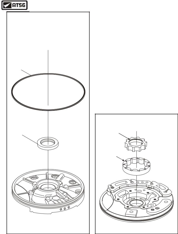
OIL PUMP EXPLODED VIEW |
|
|
3 |
4 |
|
|
6 |
|
1 |
5 |
|
2 |
|
|
7 |
|
|
|
8 |
|
|
9 |
|
|
10 |
1 |
OIL PUMP CONVERTER SEAL |
|
2 |
OIL PUMP BODY BUSHING |
|
3 |
OIL PUMP BODY TO CASE "D" RING SEAL |
|
4 |
OIL PUMP BODY |
|
5 |
OIL PUMP INNER GEAR |
|
6 |
OIL PUMP OUTER GEAR |
|
7 |
OIL PUMP STATOR/COVER |
|
8 |
OIL PUMP COVER TO BODY BOLTS (6 REQUIRED) |
|
9 |
STATOR SHAFT/COVER BUSHINGS (2 REQUIRED) |
|
10 |
STATOR SHAFT SEALING RINGS (2 REQUIRED) |
|
|
|
Copyright © 2004 ATSG |
Figure 55
32 |
AUTOMATIC TRANSMISSION SERVICE GROUP |
|
Technical Service Information
PUMP BODY |
"D" RING SEAL |
PUMP BODY |
CONVERTER SEAL |
Copyright © 2004 ATSG |
COMPONENT REBUILD SECTION
OIL PUMP ASSEMBLY
6.Install a new oil pump body converter seal, as shown in Figure 56.
7.Install new oil pump body to converter housing "D" ring seal into the groove (See Figure 56).
Caution: Ensure that "D" ring seal is not twisted in the groove.
8.Turn the oil pump body over, with the gear pocket facing up, as shown in Figure 57.
9.Lubricate both pump gears with Mercon® V transmission fluid.
10.Install the outer pump gear into the pocket with the "Notches" facing up, as shown in Figure 57.
11.Install the inner pump gear into the pocket with inside "Lip" facing up, as shown in Figure 57.
Continued on Page 34
INNER PUMP GEAR |
"LIP" FACING UP |
OUTER PUMP GEAR |
"NOTCHES" |
FACING UP |
Copyright © 2004 ATSG |
Figure 56 |
Figure 57 |
AUTOMATIC TRANSMISSION SERVICE GROUP |
33 |
|
Technical Service Information |
||
COMPONENT REBUILD SECTION |
|
|
OIL PUMP ASSEMBLY |
|
|
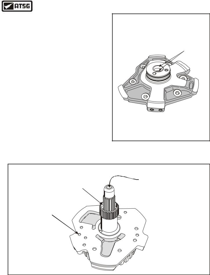
12. Inspect pump stator bushings very carefully, |
|
|
as shown in Figure 58. |
|
|
Caution: These bushings are very bad about |
|
|
wearing and create TCC code P0741. |
|
|
13. Air check the stator bushings by placing over |
|
PUMP STATOR |
the turbine shaft, as shown in Figure 59. |
|
BUSHINGS |
14. Replace the bushings as necessary using the |
|
|
proper drivers. |
|
|
Note: We recommend replacement on every |
|
|
rebuild as the bushings are now available |
|
|
from Sonnax® under number 46000-01K. |
|
|
15. If the bushings are not available, you will have |
|
|
no choice but to replace the complete pump |
|
P |
assembly, as the bushings are not serviced by |
|
6 |
U |
|
|
|
11 |
|
Ford Motor Co. |
|
4 |
|
|
|
Continued on Page 35 |
|
|
|
|
Copyright © 2004 ATSG |
|
|
Figure 58 |
AIR CHECKING THE STATOR BUSHINGS
THERE SHOULD BE NO |
APPLY 80-100 PSI |
AIR LEAKING IN BETWEEN |
AIR PRESSURE |
THE TURBINE SHAFT AND THE STATOR
HERE
BLOCK THIS
HOLE WITH
YOUR THUMB
Copyright © 2004 ATSG
Figure 59
34 |
AUTOMATIC TRANSMISSION SERVICE GROUP |
|
Technical Service Information
PUMP STATOR
SEAL RINGS
Copyright © 2004 ATSG
Figure 60
PUMP COVER TO |
PUMP BODY BOLTS |
(6 REQUIRED) |
COMPLETED |
PUMP COVER |
Copyright © 2004 ATSG |
Figure 61
COMPONENT REBUILD SECTION
OIL PUMP ASSEMBLY
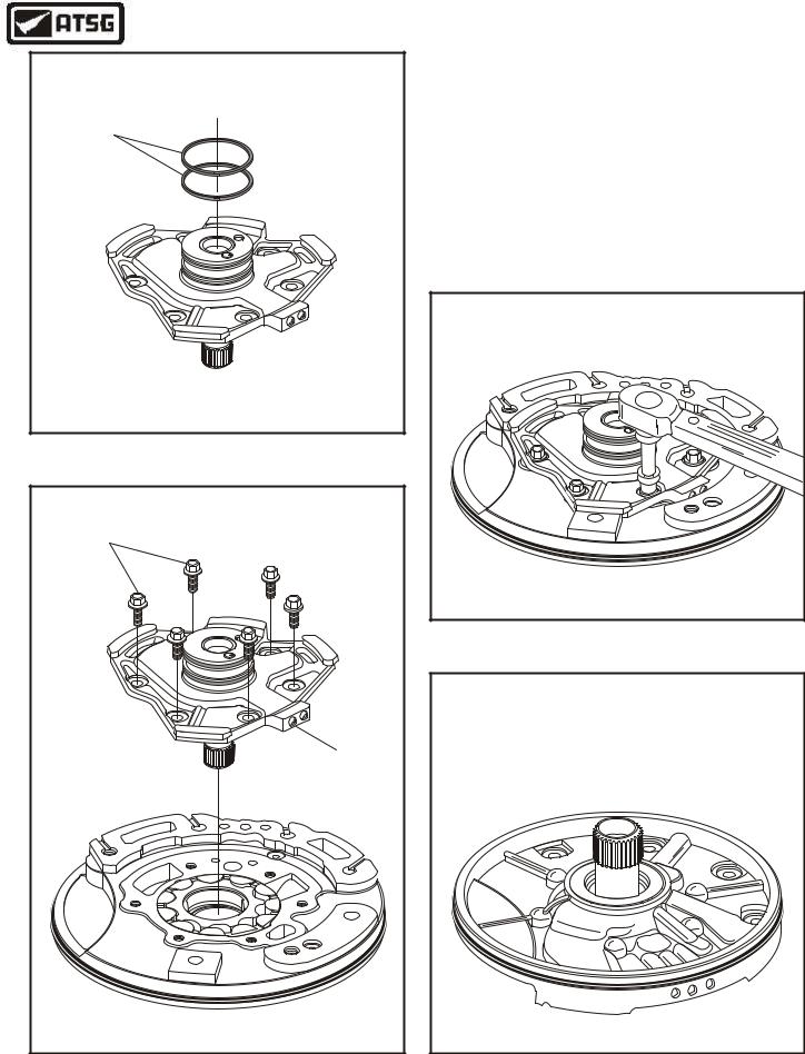
16.Install two new sealing rings into the stator grooves, as shown in Figure 60.
17.Install the completed pump stator into pump body, as shown in Figure 61, and install the six retaining bolts.
18.Torque the six pump stator retaining bolts to 13 N•m (10 ft.lb.), as shown in Figure 62.
19.Place the completed oil pump assembly aside for the final assembly process (See Figure 63).
13 N•m (10 ft.lb.) |
Copyright © 2004 ATSG |
Figure 62
COMPLETED PUMP ASSEMBLY |
Copyright © 2004 ATSG |
Figure 63
AUTOMATIC TRANSMISSION SERVICE GROUP |
35 |
|
Technical Service Information
|
|
FORWARD CLUTCH EXPLODED VIEW |
|
|
1 |
2 |
3 |
|
|
||
|
|
|
4 |
|
6 |
|
8 |
|
|
7 |
|
|
|
|
|
|
5 |
|
|
|
|
9 |
|
|
|
|
10 |
1. |
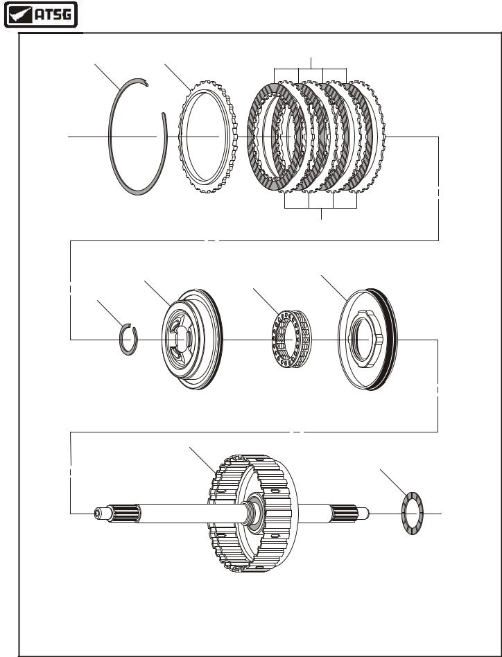
FORWARD CLUTCH BACKING PLATE SNAP RING (SELECTIVE). |
8. FORWARD CLUTCH APPLY PISTON. |
|
2. |
FORWARD CLUTCH BACKING PLATE. |
|
9. FORWARD CLUTCH HOUSING ASSEMBLY. |
3. |
FORWARD CLUTCH FRICTION PLATES (4). |
10. FORWARD CLUTCH HOUSING TO STATOR THRUST WASHER. |
|
4. |
FORWARD CLUTCH STEEL PLATES (4). |
|
|
5. |
RETURN SPRING RETAINER/BALANCE PISTON SNAP RING. |
|
|
6. |
RETURN SPRING RETAINER/BALANCE PISTON. |
|
|
7. |
FORWARD CLUTCH PISTON RETURN SPRING ASSEMBLY. |
Copyright © 2004 ATSG |
|
Figure 64
36 |
AUTOMATIC TRANSMISSION SERVICE GROUP |
|
Technical Service Information
COMPONENT REBUILD SECTION
FORWARD CLUTCH HOUSING ASSEMBLY
1.Disassemble the forward clutch housing using Figure 64 as a guide.
2.Clean all of the forward clutch housing parts thoroughly and dry with compressed air.
3.Inspect all of the forward clutch housing parts for any wear and/or damage.
4.Replace forward clutch parts as necessary.
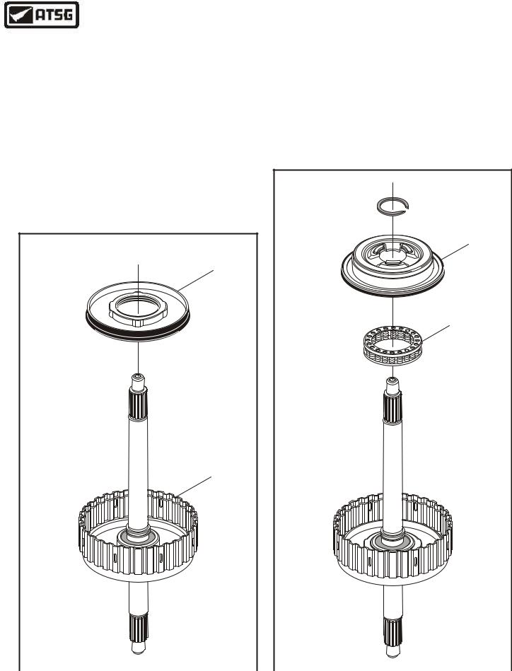
5.Lubricate forward clutch piston seal surfaces with a small amount of Trans-Jel®.
6.Install the forward clutch piston into forward clutch housing, as shown in Figure 65, with a twisting motion.
FORWARD CLUTCH
APPLY PISTON
7.Install the forward clutch piston return spring assembly, as shown in Figure 66.
8.Install the forward clutch balance piston, as shown in Figure 66, compress and install snap ring ensuring that it is fully seated.
Continued on Page 38
RETAINER
SNAP RING 
FORWARD CLUTCH
BALANCE PISTON
FORWARD CLUTCH
RETURN SPRING
FORWARD CLUTCH
HOUSING
Copyright © 2004 ATSG |
|
Copyright © 2004 ATSG |
Figure 65 |
|
Figure 66 |
AUTOMATIC TRANSMISSION SERVICE GROUP |
37 |
|
Technical Service Information
|
1 |
|
2 |
|
3 |
|
4 |
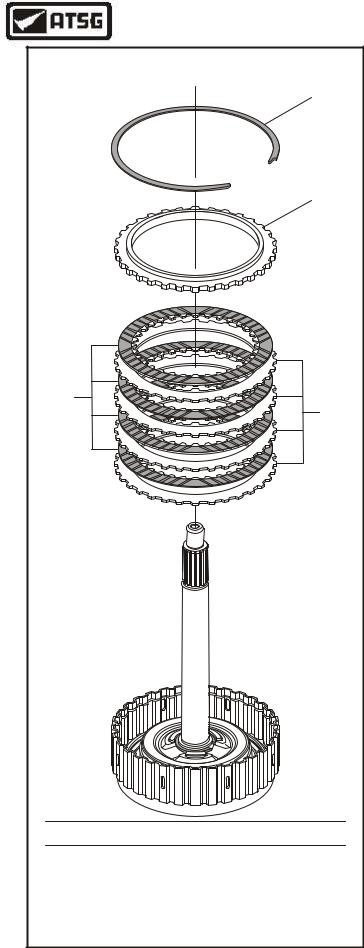
1. |
FORWARD CLUTCH BACKING PLATE SNAP RING (SELECTIVE). |
2. |
FORWARD CLUTCH BACKING PLATE. |
3. |
FORWARD CLUTCH FRICTION PLATES (4 REQUIRED). |
4. |
FORWARD CLUTCH STEEL PLATES (4 REQUIRED). |
|
Copyright © 2004 ATSG |
COMPONENT REBUILD SECTION
FORWARD CLUTCH HOUSING ASSEMBLY (cont'd)
9.Soak the new forward clutch friction plates in clean Mercon® V trans fluid for 15 minutes.
10.Install the forward clutch plates beginning with a steel plate and alternating with a lined plate, until you have installed 4 of each, as shown in Figure 67.
11.Install the forward clutch backing plate into the housing, as shown in Figure 67.
12.Install the selective forward clutch backing plate snap ring, as shown in Figure 67.
13.Tap the turbine shaft gently on the work bench to seat the snap ring against top of ring groove.
Continued on Page 39
Figure 67
38 |
AUTOMATIC TRANSMISSION SERVICE GROUP |
|
Technical Service Information
COMPONENT REBUILD SECTION
FORWARD CLUTCH HOUSING ASSEMBLY (cont'd)
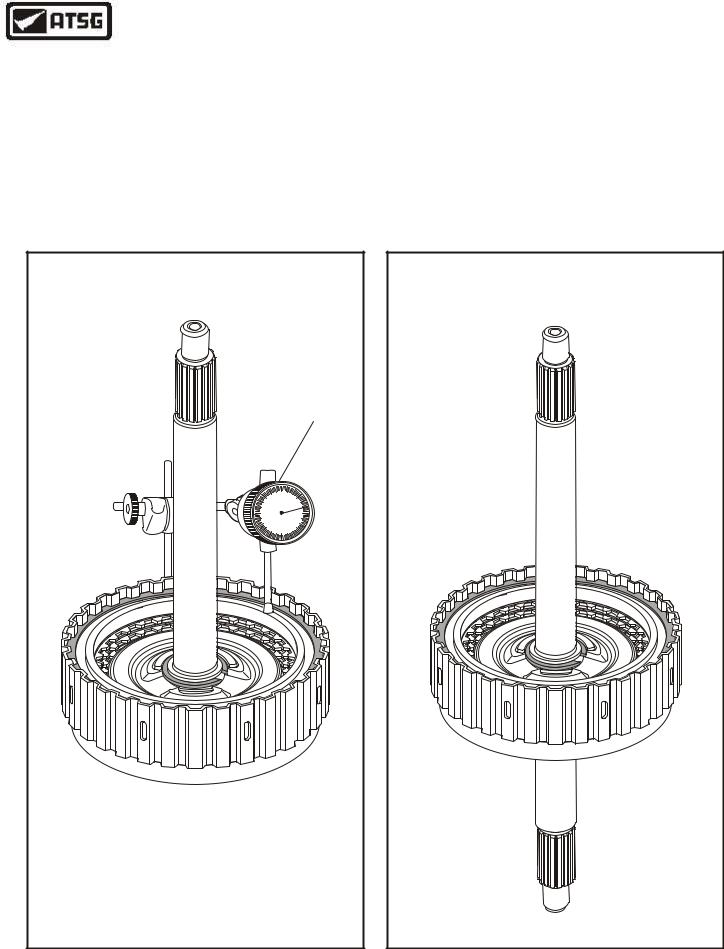
14.Install dial indicator, as shown in Figure 68, with the plunger resting on backing plate, and zero the dial indicator.
15.Lift up both sides of clutch pack with scribes to measure for proper clutch pack clearance.
16.Forward clutch pack clearance should be,
1.5to 1.8 mm (.059" to .071"), as shown in Figure 68.
17.Change the selective snap ring as necessary to obtain the specified clutch clearance and then recheck the clutch pack clearance.
18.Set the completed forward clutch housing aside for the final assembly process (See Figure 69).
FORWARD CLUTCH CLEARANCE SHOULD BE |
|||
1.5 |
- 1.8 MM (.059" - .071") |
||
|
|
|
DIAL |
|
|
|
INDICATOR |
|
10 |
0 |
10 |
|
|
||
|
20 |
|
20 |
|
30 |
|
30 |
|
40 |
|
40 |
|
50 |
0 |
50 |
Selective Snap Ring Thickness Available |
|||
1.15 |
- 1.25 mm (.045" - .049") |
||
1.35 |
- 1.45 mm (.053" - .057") |
||
1.55 |
- 1.65 mm (.061" - .065") |
||
1.75 |
- 1.85 mm (.069" - .073") |
||
1.95 |
- 2.05 mm (.077" - .081") |
||
2.15 |
- 2.25 mm (.085" - .089") |
||
|
Copyright © 2004 ATSG |
||
COMPLETED FORWARD CLUTCH HOUSING
Copyright © 2004 ATSG
Figure 68 |
Figure 69 |
AUTOMATIC TRANSMISSION SERVICE GROUP |
39 |
|

Technical Service Information
CAUTION - CAUTION - CAUTION
Ford vehicles equipped with the 4F27E transaxle may exhibit Failure due to Lack of Lubrication. The cause may be, a restricted Transmission Oil Cooler limiting the amount of lubrication oil, which is fed to the rear case fitting in the rear cover. The Direct/Reverse Drum bushing and the Sealing Ring Journal on the Rear Cover are the most common failures with lack of lubrication, so inspect these parts with extra care.
If failure of these parts is observed, it will be necessary to replace them with new, along with the transaxle oil cooler. If these parts have not yet failed, it will still be necessary to replace the transaxle oil cooler, as shown below.
Transaxle Oil Cooler
Ford Part Number
XS4Z-7A095-BA
Copyright © 2004 ATSG
Figure 70
COMPONENT REBUILD SECTION
Before proceeding with the component rebuild section, it is imperative that the reverse clutch drum bushing and the journal and seal ring area of the end cover be inspected very closely for any wear and/or damage, as shown in Figure 71.
Ford Motor Company recommends replacement of the transaxle cooler on all rebuilds.
Inspect This Bushing |
Inspect Journal |
And Seal Ring Area |
Copyright © 2004 ATSG |
Figure 71
40 |
AUTOMATIC TRANSMISSION SERVICE GROUP |
|

Technical Service Information
COMPONENT REBUILD SECTION
REAR END COVER
1.Remove and discard the direct clutch seal rings and the reverse clutch seal rings.
2.Inspect the end cover journal and sealing ring area for any wear and/or damage.
3.Clean the end cover thoroughly and dry with compressed air.
4.Install new reverse clutch sealing rings into the grooves, as shown in Figure 72, and ensure that they are properly seated.
5.Install new direct clutch sealing rings into the grooves, as shown in Figure 72, and ensure that they are properly seated.
6.Install the selective direct clutch hub bearing race, as shown in Figure 72, and retain with a small amount of Trans-Jel®.
7.Set the completed end cover assembly aside for the final assembly process (See Figure 73).
|
109 |
|
12 |
|
110 |
12 DIRECT CLUTCH SEALING RINGS (2 REQUIRED). |
|
109 |
DIRECT CLUTCH HUB BEARING RACE (SELECTIVE). |
110 |
REVERSE CLUTCH SEALING RINGS (2 REQUIRED). |
|
Copyright © 2004 ATSG |
Figure 72
COMPLETED END COVER ASSEMBLY |
Copyright © 2004 ATSG |
Figure 73
AUTOMATIC TRANSMISSION SERVICE GROUP |
41 |
|