

Fundamentals of the Physics of Solids / 08-Methods of Structure Determination
.pdf8.2 Experimental Study of Di raction |
261 |
8.2 Experimental Study of Di raction
The previous introduction into the theory of di raction has shown that structural information can be extracted from reciprocal-lattice vectors and the intensity of Bragg peaks by determining the directions in which elastically scattered beams emerge when a beam of known wavelength is shone on a sample from a well-defined direction. In an ideal experimental setup the source provides a well-collimated beam of monoenergetic (monochromatic) particles, that is, the wave vector k is the same for each particle. When the beam is not monochromatic, a single-crystal monochromator can be inserted so that only a particular wavelength λ that satisfies the Bragg condition is reflected. The wavelength of the monochromatized beam can be changed by rotating the monochromator.
The number of particles scattered elastically in a certain direction is then measured by suitable detectors. For a particular value of λ, the Bragg peak can be found by varying the angle 2θ of the detector. In the case of X-ray di raction the intensity of the scattered beam is often detected using a film instead of a photon counter. The schematic setup of the measurement is shown in Fig. 8.9.
Collimators
Source
Mono- |
|
|
chromator |
2 |
Detector |
|
||
|
|
|
|
Sample |
|
Fig. 8.9. Schematic setup of di raction measurements
8.2.1 Characteristic Properties of Di erent Types of Radiation
Let us now examine what photon, neutron, and electron energies provide the most e ective wavelength region for structural analysis. We shall start o with the relationship between the photon energy and wavelength, ε = cp = hc/λ. When photon energies are measured in units of keV and wavelengths in angstroms, the values listed in Appendix A for physical constants give
λ [Å] = |
|
. |
(8.2.1) |
ε [keV] |
To obtain an X-ray beam with a wavelength of 1 Å, photon energies on the order of 10 keV are necessary.

262 8 Methods of Structure Determination
Photons emitted in a synchrotron by accelerated electrons provide intense and collimated beams with a wide energy spectrum. Then a photon beam propagating in a well-defined direction is selected, in which photon energies are an order of magnitude larger than in ordinary X-rays, i.e., whose wavelength is on the order of 10−1 Å. This provides a much better resolution in momentum space than a traditional X-ray source. Because of the large intensity, di raction measurements may be performed even on tiny (μg-sized) crystallites; or, short measurement times open the way to studying time-varying structures with a time resolution of about a millisecond.
Neutron energies are given by the relation ε = p2/2mn, where mn = 1.675 × 10⁻²⁷ kg is the neutron mass. The momentum p is related to the de Broglie wavelength λ by p = h/λ, thus in terms of the energy measured in electronvolts, the wavelength in angstroms is given as
λ [Å] = |
0.28 |
(8.2.2) |
(ε [eV])1/2 . |
To obtain a wavelength of about 1 Å, the energy has to be ε ≈ 0.1 eV. This energy is close to the thermal energy at room temperature.8 Thermal neutrons
– neutrons emerging from a fission reactor and then slowed down to thermal energies by the moderator – are thus of the desired wavelength.
Because of their smaller mass, the wavelength–energy relationship for electrons derived from the formula ε = p2/2me is
λ [Å] = |
12.247 |
(8.2.3) |
(ε [eV])1/2 . |
To achieve a wavelength of 1 Å, electrons need to be accelerated to energies on the order of 100 eV. The experimental method using electrons with energies between 10 and 300 eV (wavelength: 0.7–4 Å) is called low-energy electron di raction (LEED). When the beam energy is higher, we speak of high-energy electron di raction (HEED).
Since di raction is an elastic process, the energy of the scattered particle is irrelevant. From this point of view there should be no di erence in the applicability of the three types of beam. Particle energies become important when we turn to the suitability of each particular type of radiation to the investigation of the internal dynamics of solids (where typical energies range from 10 to 100 meV). The accuracy of measuring changes in energy caused by low-energy excitations is limited by the resolution of the measuring apparatus. The energy 10−1 eV of one-angstrom neutrons is ideally suited to studying internal excitations. The amount of information that can be gathered with electrons and photons is much smaller because of the high energy of the particles.
8 According to the equipartition theorem, the mean kinetic energy of particles at temperature T is 32 kBT . At room temperature this corresponds to an energy of 38 meV or a wavelength of 1.4 Å.

8.2 Experimental Study of Di raction |
263 |
Even though the only relevant quantity for the Bragg or Laue condition is the wave vector of the incoming radiation (since the energy is irrelevant in elastic scattering), the three radiations are not equally suited to probing a given structure via di raction. As each radiation interacts di erently with the various constituents of the sample, the best choice depends on the particular problem. Photon and electron beams interact with electrons in the solid, thus information is gathered directly about the spatial distribution of electrons. Neutrons are scattered by nuclei, and they interact with the electron cloud, too, if the latter has a magnetic moment. They can thus probe atomic as well as magnetic structures. Neutron di raction measurements may complement the results obtained via X-ray di raction even for magnetically disordered systems. The cross section for X-ray scattering depends on the number of electrons in the electron cloud: it goes with the square of the atomic number. The cross section for neutron scattering, on the other hand, is not a monotonic function of the atomic number, and it also depends on the isotopic composition. Depending on the composition of the sample, either type of radiation may be better suited to specifying atomic positions within the primitive cell. For example, unlike X-ray scattering, neutron scattering is particularly adapted for determining the structure of samples that contain hydrogen.
By using a radiation whose wavelength is much smaller than the atomic dimensions, the spatial distribution of electron density may also be mapped out. HEED is the method of choice for this, as the wavelength of 100 keV electrons is λ ≈ 0.04 Å. Another advantage of HEED over LEED is that high-energy electrons can penetrate deep inside the sample, thus this method permits us to study the interior of the sample. Since beams used in LEED usually penetrate only into the topmost layer of a few angstroms, this method is adapted for the study of the structure at or close to the surface.
How much of the radiation is absorbed by the sample; how deeply does it penetrate into the sample, and so to what extent can bulk properties be studied? These questions arise for all other types of radiation as well. Neutrons can penetrate most deeply into the sample. Depending on the material, they may penetrate through a sample several inches thick without absorption. On the other hand, 1 Å X-ray photons typically penetrate into metals only to a depth of 30–100 μm – but even this may be enough to measure bulk properties. Since their penetration depth is much larger in the appropriate wavelength region, synchrotron radiation obviously probes bulk properties.
There is, nevertheless, another typical length that has to be taken into account, the extinction length. Its typical value is 10 μm for X-rays, 100 μm for neutrons, and a mere 10−2 μm for electrons. For thinner samples the kinematic theory of di raction may be used without reservations. For thicker ones it can only be used if the crystal is not ideal but features a mosaic structure.9 Otherwise internal cancellations can no longer be ignored, and thus the dynamical theory of di raction has to be employed.
9 Mosaic structures will be presented in the next chapter.

264 8 Methods of Structure Determination
8.2.2 The Ewald Construction
According to conditions (8.1.1) and (8.1.5) for di raction, when a beam of a specific wavelength λ is incident on a crystalline sample, scattered radiation emerges only in some particular directions. The Ewald construction10 is of great help in visualizing this.
Since the condition for di raction is most easily expressed in terms of reciprocal-lattice vectors, we shall consider the reciprocal lattice of the putative Bravais lattice of the examined crystal. Figure 8.10 shows its sectional view in the plane of scattering. The incident wave vector k is drawn in such a way that its tip is at a lattice point of the reciprocal lattice. Centered at the starting point of the arrow k, a sphere (circle) of radius k = |k| is then drawn. This is the Ewald sphere.
Ghkl
k'
2 
k
Fig. 8.10. The Ewald construction illustrating the condition for di raction in the reciprocal lattice
By its construction, the Ewald sphere passes through a point of the reciprocal lattice (lying at the tip of vector k). If it happens to pass through other points of the reciprocal lattice then the Laue condition is satisfied by the vectors k drawn from the center of the sphere to each of these points as |k| = |k | and k −k is a vector Ghkl of the reciprocal lattice. The Bragg peak with indices hkl is observed in the direction of k .
In LEED the wavelength is much smaller than the lattice constant, and so the magnitude of the wave vector – the radius of the Ewald sphere – is large compared to the lattice constant of the reciprocal lattice. Because of its small curvature, the Ewald sphere may pass very close to a great number of reciprocal-lattice points. When the sample is not too large, many reflections appear close to the incident direction because of the finite width of the di raction peaks.
10 P. P. Ewald, 1913.

8.2 Experimental Study of Di raction |
265 |
This is not the case for X-ray and neutron di raction. When the orientation of the crystal with respect to the incident beam is arbitrary, there may be no scattering at all. To meet the Bragg condition, one has to change either the wavelength of the incident beam by rotating the axis of the single-crystal monochromator; or the relative orientation of the beam and the crystallographic axes by rotating the sample; or the direction of the detected (scattered) beam by moving the particle counter. When the detector is a film or a set of counters that covers a large proportion of the total solid angle 4π, there are still two degrees of freedom in choosing the wavelength of the incident beam and the relative orientation of the beam and the crystal at will. In the most sophisticated method the wavelength is fixed and the complete di raction pattern is measured for several orientations of the sample. Simpler methods can be employed when the task is not the precise determination of a completely unknown structure but the quick verification of the putative structure or the determination of the lattice parameters for a known structure type.
8.2.3 Di raction Methods
One possibility is to irradiate a sample with a collimated but not monochromatic beam that contains all the wavelengths from λmin up to λmax. This is called the Laue method. The direction of the wave vector is now definite, however its magnitude ranges between kmin and kmax.11 If the Ewald spheres were drawn for all possible values of the incoming wavelength, they would fill the region between two spheres of radii kmin and kmax, as shown in Fig. 8.11.
The Laue condition is satisfied by every vector of the reciprocal lattice within this region, and so scattering is observed in several directions. Based on the Ewald construction it can be shown that if the orientation of the sample is such that the beam is incident along a high-symmetry direction of the crystal then the Laue pattern also possesses the rotational symmetries of the crystal around the axis. Figure 8.12 shows Laue patterns with the hexagonal structure of beryllium and the trigonal structure of quartz.
Another method for meeting the condition for di raction is to rotate the crystal around an axis perpendicular to the direction of the incident beam – or to vibrate it covering a su ciently large angular range. This is the rotatingcrystal method.
The sample is oriented in such a way that the axis of rotation should be along a crystallographic axis – for example, in the direction of the primitive vector a1 of the crystal lattice. Because of the construction of the reciprocal lattice the plane spanned by two appropriately chosen primitive vectors (b2 and b3 in our case) is perpendicular to the axis of rotation. When the Laue condition is satisfied by a reciprocal-lattice vector in this plane, the propagation direction of the scattered beam also lies in the same plane. To determine
11Synchrotrons provide such beams, at much higher intensities than traditional X-ray sources. This is why the method is rapidly gaining popularity.

266 8 Methods of Structure Determination
G
k'
k
kmin
kmax
Fig. 8.11. Reciprocal-lattice vectors satisfying the condition for di raction in the Laue method
Fig. 8.12. Di raction patterns along the direction of a crystallographic axis in beryllium and quartz obtained with the Laue method
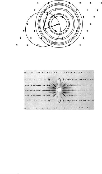
the directions satisfying the condition for di raction, Fig. 8.13 shows the reciprocal lattice and the Ewald sphere for a particular orientation of the crystal.
When the crystal is rotated, the reciprocal lattice co-rotates with it. In the Ewald construction this corresponds to the rotation of the reciprocal lattice about the origin. Scattering occurs when a rotated reciprocal-lattice vector is exactly on the surface of the Ewald sphere. Recorded on a film, the scattered radiation appears as a series of dots. Further series of dots may appear above and below this scattering plane. These di raction peaks correspond to reciprocal-lattice vectors that have a nonvanishing component along the axis of rotation. Such an experimental record is shown in Fig. 8.14.
In the third widely used method measurements are not performed on a single crystal with a definite orientation but on a powder sample that contains
8.2 Experimental Study of Di raction |
267 |
 k'
k'
k
Fig. 8.13. The Ewald construction for a crystal rotating around an axis perpendicular to the direction of the incident beam. The solid circle is the section of the Ewald sphere, while dashed circles show the loci of the tips of reciprocal-lattice vectors when the sample is rotated
Fig. 8.14. Di raction pattern of a quartz crystal obtained with the rotating-crystal method
grains with all possible orientations. The powder method was first developed by P. Debye12 and P. Scherrer in 1916, hence it is also called the Debye– Scherrer method. To interpret the di raction pattern assume that the Laue condition is met for a certain grain along a direction k by the reciprocallattice vector G. Since the same vector G points in di erent directions in other grains, scattered beams emerge in each direction for which the Laue condition is satisfied in some grain by the given G. Since the crystallographic orientation of the grains is assumed to have a continuous distribution in the powder sample, for a fixed k the tips of possible k s lie on the surface of a sphere of radius |G|. On the other hand both the starting point and the
12Petrus (Peter) Josephus Wilhelmus Debye (1884-1966) was awarded the Nobel Prize in Chemistry in 1936 “for his contributions to our knowledge of molecular structure through his investigations on dipole moments and on the di raction of X-rays and electrons in gases”.

268 8 Methods of Structure Determination
end point of the vector G have to be on the surface of the Ewald sphere determined by the vector k. Therefore scattering occurs in directions that lie on the intersection line of the two spheres. This is shown in Fig. 8.15.
k’
G
k
|G|
Fig. 8.15. The Ewald construction for the powder method
It is immediately seen from the figure that scattered beams emerge at angles 2θ with the incident beam for which |G| = 2k sin θ. For such angles the scattered beams surround the direct beam conically. When recorded on a film, these appear as rings. Figure 8.16 shows the distribution of scattered radiation in a one-dimensional section.
|
|
100 |
200 |
|
|
|
|
|
|
|
|
|
|
|
|
|
|
|
|
|
|
90 |
|
|
220 |
|
NaCl |
(Cu K ) |
|
|
|
80 |
|
|
|
|
|||
|
bitraryunits) |
|
|
|
|
|
|||
Intensity |
70 |
|
|
|
|
|
|
|
|
60 |
|
|
|
|
|
|
|
||
50 |
|
|
|
|
|
|
|
||
40 |
|
|
|
|
|
|
|
||
|
|
|
|
|
|
|
|
||
|
(ar |
30 |
|
|
|
222 |
|
|
|
|
20 |
111 |
|
|
420 |
|
|||
|
|
|
|
|
|
||||
|
|
|
|
|
|
422 |
|
||
|
|
|
|
|
|
400 |
|
||
|
|
10 |
|
|
311 |
333 |
|||
|
|
|
|
311 |
|
||||
|
|
|
|
|
511 |
||||
|
|
|
|
|
|
|
|
||
|
|
0 |
30 |
40 |
50 |
60 |
70 |
80 |
90 |
|
|
|
|||||||
|
|
|
|
|
2 (degrees) |
|
|
||
Fig. 8.16. Di raction pattern of sodium chloride crystal, obtained with the Debye– Scherrer method. Adapted from B. E. Warren, X-Ray Di raction (1969)
By measuring the angle, one can determine the length of the reciprocallattice vectors. This is not enough to identify a completely unknown structure
– however, when the symmetries of the crystal are known, it provides one of the quickest methods for measuring the lattice constants.
8.3 Other Methods of Structure Determination |
269 |
8.3 Other Methods of Structure Determination
The aim of di raction techniques based on elastic scattering is to determine the internal structure of bulk material or the surface structure. In both cases, periodicity is assumed to extend over macroscopic distances. Besides, there exist other methods of structural analysis for the determination of the local environment of an atom. These are particularly important when the system to be examined is not regular – but they may, of course, be used to study crystalline samples, too. Probably the most adapted technique is EXAFS spectroscopy.13 As its name reveals, it uses X-rays – however, they are not reflected from the sample but the fine structure of their absorption spectrum is studied.
When a photon of the incident X-ray beam is absorbed, its energy is transferred to the system of electrons. The linear absorption coe cient μ is defined through the relation
I = I0 exp(−μ/L) , |
(8.3.1) |
where L is the thickness of the sample, while I0 and I are the incident and transmitted intensities. In general, μ is a smooth function of the photon energy
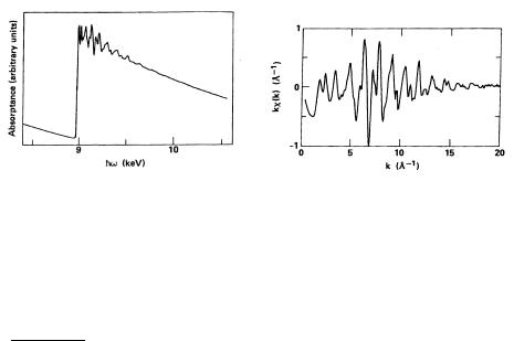
– except for the values that correspond to the ionization energies of bound states. At these energies sharp thresholds, absorption edges appear, since new channels become available for absorption. As shown in Fig. 8.17, the energy dependence of absorption is not really smooth in the vicinity of the absorption edge, either. EXAFS is concerned with the study of this fine structure.
(a) |
(b) |
Fig. 8.17. (a) Absorption edge on the K shell of copper. (b) Fine structure of the absorption edge [T. M. Hayes and J. B. Boyce, Solid State Physics, Vol. 37, 173 (1982)]
1–10 Å (1–10 keV) photons are energetic enough to knock out electrons even from deep levels (e.g., the 1s level). For energies in excess of the threshold value, the excited electron propagates as a spherical wave and is scattered
13 EXAFS stands for extended X-ray absorption fine structure.

270 8 Methods of Structure Determination
by adjacent atoms. These scattered waves interfere with the original wave. Depending on the photon wavelength (energy) and the geometry of the neighbors, this interference can be constructive or destructive. The energy dependence of absorption may be written as
σ(E) = σ0(E)[1 + χ(E)] , |
(8.3.2) |
where σ0(E) is a smooth absorption curve, and χ(E) accounts for the interference due to neighbors. Expressed in terms of the wave number rather than the energy, χ(E) is replaced by χ(k), which can be related to the Fourier transform of the radial distribution function. From measured data conclusions can be drawn about the local environment.
Like X-ray and neutron di raction, EXAFS spectroscopy probes the interior of the sample. As it has been mentioned, electron di raction is well suited to determining the structure of the surface layers only, since electrons do not penetrate su ciently deeply into the sample. Nonetheless the study of solid surfaces is a fascinating subject in itself, and so several novel methods have been devised. For example, G. Binnig and H. Rohrer14 built the scanning tunneling microscope (STM) in 1981.
The basic idea is to place the tip of a very thin stylus close to a conducting surface, at a distance of order 10 Å. The stylus itself is metallic and the tip is formed by a single atom. When a voltage is applied between the tip and the surface, electrons can tunnel through the junction, giving a measurable tunneling current. The scanning process consists of moving the tip laterally along the surface; its vertical position is controlled using piezoelectric materials. In the usual mode of operation current is kept fixed during scanning and the perpendicular deflection required to keep the current constant is monitored. The exponential dependence of the tunneling current on distance allows one to take atomic resolution images of the surface.
Obviously, the method is appropriate for the study of metallic surfaces only. For nonmetallic surfaces the atomic force microscope (AFM)15 can be used – an instrument that measures the force between the tip of the stylus and the sample. Figure 8.18 shows the image of a surface taken by an AFM. It clearly shows that surface reconstruction gives rise to a layer with new symmetry.
14Gerd Binnig (1947–) and Heinrich Rohrer (1933–) shared the Nobel Prize in 1986 “for their design of the scanning tunneling microscope”.
15G. Binnig, C. F. Quate, and Ch. Gerber, 1986.