

Fundamentals of the Physics of Solids / 09-The Structure of Real Crystals
.pdf9.2 Line Defects, Dislocations |
283 |
Frenkel Defects
When a vacancy is generated, the atom may not di use to the surface but become trapped at a nearby interstitial site, as shown in Fig. 9.5. In ionic crystals the complex of a vacancy and a nearby interstitial of the same ion (which thus carry opposite e ective charges) is called a Frenkel defect.3
The equilibrium concentration of Frenkel defects can be determined along the same lines as the concentration of simple vacancies. Suppose the sample has N atomic positions, of which n are left vacant. Since the atoms do not di use to the surface but become trapped at interstitial sites, the volume does not change in a first approximation. We shall denote the number of possible interstitial sites by Nint. If the n vacancies are formed randomly at the N atomic positions and the displaced ions occupy the interstitial sites at random as well, the configurational entropy is given by
Sconfig = kB ln |
N ! |
|
Nint! |
. |
(9.1.18) |
(N − n)!n! |
|
(Nint − n)!n! |
If the formation energy of a Frenkel defect is ε0, minimization of the free energy leads to
in the |
N, N |
int |
n |
n = |
N Nint |
exp(−ε0/2kBT ) |
(9.1.19) |
|
|
limit. |
|
||||
Unlike alkali halides, silver halides contain such defects. After the formation of vacancies on the sublattice of silver ions, these positively charged ions become trapped at interstitial sites. Frenkel defects are also found in alkalineearth fluorides. Formation energies are listed in Table 9.2.
In principle, another type of defect pair can exist, in which all ions sit on lattice sites but a cation and a nearby anion swap positions. In ionic crystals this is highly prohibited by the unfavorable e ective charge that would appear and the large energy involved. However, such defects are indeed observed in intermetallic compounds, where swapping between di erent components entails a smaller increase in energy. They are called antisite defects. More generally, an antisite defect AB is an atom of type A that occupies a wrong site on sublattice B. Such individual antisite defects are of special interest in doped semiconductor compounds.
9.2 Line Defects, Dislocations
Atoms in a crystal may become misplaced with respect to their regular position along a whole line because of very large internal mechanical strains and stresses occurring while working the material. When a crystal is bent or twisted, atomic layers may slip on each other in such a way that the majority of the atoms around the slip – except for the vicinity of a line – find
3 J. Frenkel, 1926.

284 9 The Structure of Real Crystals
themselves in another locally aligned environment. Defects of this kind may develop during crystal growth as well. They are called dislocations.
As a large number of bonds are broken between atoms along the line, the energy of a dislocation is much higher than that of a vacancy or an interstitial, consequently dislocations are not generated thermally, only during mechanical working. The density of dislocations depends strongly on the preparation conditions. In very carefully grown germanium or silicon crystals they may be as low as 102–103/cm2, while in metals subject to high mechanical strains they may range up to 1010–1012/cm2. Their presence strongly a ects the mechanical properties of materials; they also play an important role in the growth of crystals. However, we do not discuss these points any further here, as we focus on the issues of structure only.
9.2.1 Edge and Screw Dislocations
The structure around line defects is most easily illustrated using the Volterra construction (or Volterra process).4 An imaginary cut is made into a crystal, terminating in its interior on a line called the dislocation line. Its shape being irrelevant, the cut is chosen, for simplicity, to be in a flat plane. In the next step the two parts separated by the cut are displaced relative to one another, allowing elastic deformations of the lattice near the dislocation line. If the relative displacement is a translation vector of the lattice, then – except for the region close to the dislocation line – the two parts are in registry, and can be joined back together to restore the crystalline order. Naturally, if the displacement vector is not in the cut plane, matter has to be added to or removed from the crystal. The Volterra construction is illustrated schematically in Figs. 9.6 and 9.7 showing the crystal before and after the displacement for two di erent cases.
Fig. 9.6. Volterra construction of an edge dislocation: a part of the crystal is slipped along a cut. The arrow shows the direction of slip, which is perpendicular to the dislocation line
4 V. Volterra, 1907.

9.2 Line Defects, Dislocations |
285 |
Figure 9.6 shows the case where the displacement is perpendicular to the dislocation line. It is clearly seen that the defect – the “imperfect” region – is limited to the vicinity of the dislocation line. This type of line defect is called an edge dislocation.5
When the crystal is considered as an elastic medium, one side is compressed and the other is stretched, giving rise to elastic stress. The energy of dislocation can be determined from this elastic energy.
Fig. 9.7. Formation of a screw dislocation: an atomic layer is slipped on another in a part of the sample
The situation is slightly di erent when the two parts are slipped relative to each other parallel to the dislocation line, as shown in Fig. 9.7. The arrangement of atoms in the layers below and above the cut plane is shown in Fig. 9.8(a). Misalignment is again limited to the vicinity of a line. It is clear from the figure that by making a full turn around the dislocation line in a crystal plane perpendicular to it, one arrives at the atomic layer just below or just above. If traveling around is continued in the same way a spiral, a screw is traced out. This type of defect is therefore called a screw dislocation or sometimes a Burgers dislocation.6
More general dislocations may arise when the dislocation line is not straight. In such cases it will be parallel or perpendicular to the slip vector only exceptionally. An example is shown in Fig. 9.8(b), with the atomic arrangement in the layers below and above the cut plane. The atomic arrangement shown at the bottom of the figure is similar to that of a screw dislocation, however it is transformed into an edge dislocation inside the sample. This type of dislocation is called a mixed dislocation.
5Edge dislocations are sometimes called Taylor–Orowan dislocations, although the concept of dislocation was introduced in 1934 by three researchers independently of each other, E. Orowan, M. Polányi, and G. I. Taylor.
6J. M. Burgers 1939.
286 9 The Structure of Real Crystals
Burgers |
vector |
(a) |
(b) |
Fig. 9.8. Atomic positions above (large empty circles) and below (small full circles) the cut plane for (a) a screw dislocation; (b) a screw dislocation being transformed into an edge dislocation (mixed dislocation)
9.2.2 The Burgers Vector
Dislocations are characterized first by the dislocation line – along which regular order is disrupted –, and second by the vector specifying the relative displacement of the parts below and above the cut. However, as it has been mentioned, the cut plane does not have any physical significance. The Volterra construction of line defects served only as an illustration of dislocations. To unambiguously specify the displacement of atomic layers we adopt the method introduced by J. M. Burgers in 1939. First, a direction is associated with the dislocation line and a lattice point S that is distant from the dislocation is selected. Then, starting from S and staying all the time in the region where the local atomic environment is undistorted, a closed path encircling the dislocation is traversed, in counterclockwise sense when viewed from the chosen direction. The path may be chosen at will, it should just contain the same number of steps to the left as to the right, upward as downward, and forward as backward – more precisely, the number of steps in the direction of each primitive vector ai (i = 1, 2, 3) should be the same as in the opposite direction −ai. The traversed path is called the Burgers circuit. In crystals free of dislocations any such path terminates on the starting point S. However, when a dislocation is encircled, the path fails to close, as shown in Fig. 9.9 in the plane perpendicular to the dislocation line. No matter how the Burgers circuit is chosen for a fixed starting point S, it always terminates on the same lattice point F , which is now di erent from S. Displacement through a further – not necessarily primitive – lattice vector is required to close the circuit around the dislocation, and thus get back from F to S. The lattice vector pointing from F into S is called the Burgers vector of the dislocation.
9.2 Line Defects, Dislocations |
287 |
S F |
S b F |
S b
b
F
(a) |
(b) |
(c) |
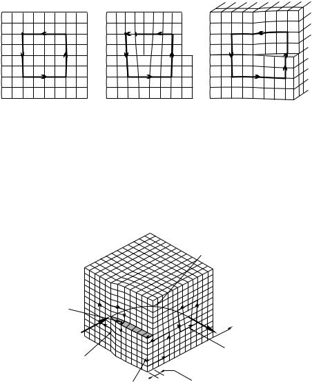
Fig. 9.9. The Burgers circuit and the Burgers vector (a) in a regular crystal; (b) around an edge dislocation; (c) around a screw dislocation
As shown in Fig. 9.9(b), the Burgers vector is perpendicular to the direction of the dislocation line for edge dislocations, while for screw dislocations one or more extra steps have to be made along the dislocation line to have the Burgers circuit closed. The Burgers vector is therefore parallel to the dislocation line in this case.
Dislocation
line
Burgers
vector
|
|
Burgers circuit |
Burgers circuit |
|
around an edge-type |
|
dislocation |
|
around a screw-type |
|
|
|
|
|
dislocation |
|
|
|
Burgers circuit |
Slip distance |
|
|
|
|
around a |
|
|
perfect region |
|
Fig. 9.10. Three Burgers circuits in a crystal with mixed dislocation: in a defectfree region, around the dislocation line in a region where it is of screw-type, and where it is of edge-type
We have seen that the dislocation line is not always straight: it may change its direction in the crystal – and along with it its character, too. Even so, regardless of the particular choice of the Burgers circuit, as long as it encircles
288 9 The Structure of Real Crystals
the dislocation line, the same Burgers vector is obtained. This is illustrated in Fig. 9.10. The dislocation shown here looks like a screw dislocation from the front and an edge dislocation from the right – nevertheless regardless of the particular choice of the Burgers circuit, the same Burgers vector is obtained when the dislocation line is encircled in the same sense.
9.2.3 Dislocations as Topological Defects
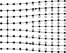
The independence of the Burgers vector of the circuit encircling the dislocation indicates that it is a topological property of the atomic arrangement around the dislocation. For a precise illustration consider a two-dimensional section of a crystal with a dislocation and a Burgers circuit Γ in it. Atomic positions in the perfect crystal are marked next to the actual atomic positions in Fig. 9.11.
1 |
2 |
3 |
|
|
6 |
7 |
8 |
9 |
|
|
|
4 |
5 |
||||
|
|
|
|
|
|
|
|
|
27 |
|
|
|
|
|
|
|
10 |
26 |
|
|
|
|
|
|
|
11 |
25 |
|
|
|
|
|
|
|
12 |
|
|
|
|
|
|
|
|
|
24 |
|
|
|
|
|
|
|
13 |
|
|
|
|
|
|
|
|
|
|
|
|
|
|
|
|
|
14 |
23 |
22 |
21 |
20 |
19 |
|
|
|
15 |
18 |
17 |
16 |
|
|||||
|
|
|
|
|
Fig. 9.11. Displacement of the atoms on a Burgers circuit in a plane perpendicular to the dislocation with respect to their positions in a perfect crystal
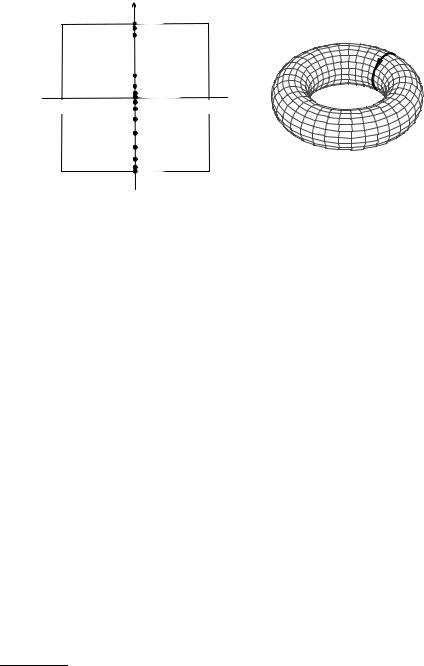
Along the Burgers circuit, where the lattice shows an almost perfect periodicity, the displacement caused by the dislocation can be defined as the vector from the closest lattice point of the ideal crystal to the actual atomic position. Thus by definition all possible displacements lie inside the Wigner–Seitz cell. These displacements are shown in Fig. 9.12(a). As the Burgers circuit is traversed, the displacement of subsequent lattice points increases; it jumps to an equivalent value (from ux = a/2 to ux = −a/2) when the boundary of the Wigner–Seitz cell is reached, and then approaches zero. The sequence of points in the (ux, uy) plane can be viewed as a mapping of the Burgers circuit (defined in real space) to displacement space.
Far from the dislocation core – i.e., the dislocation line – the displacement varies only slightly from one lattice point to the next, and so a continuous displacement field u(r) may be defined. While traversing the Burgers circuit
a/2
(a)
u |
|
|
y |
|
|
a/2 |
9 15 |
|
8 |
||
7 |
||
|
6
 5
5
4 |
|
|
2 |
3 |
|
1, 23 27 |
||
22 |
||
21 |
||
|
||
20 |
|
|
|
19 |
|
18 |
|
|
|
17 |
|
16 |
9 15 |
|
a/2 |
||
|
9.2 Line Defects, Dislocations |
289 |
 ux a/2
(b)
Fig. 9.12. (a) Displacement of the atoms around the Burgers circuit in Fig. 9.11 in the Wigner–Seitz cell of the lattice. (b) Mapping of the Burgers circuit into the torus in displacement space with periodic boundary conditions
around the dislocation in real space, the displacements u(r) trace out a piecewise continuous closed path in displacement space. The discontinuities arise from jumps between equivalent boundary points of the Wigner–Seitz cell.
When the derivative of the displacement field with respect to the arc length of the Burgers circuit is integrated along the circuit, the result is nonzero even though the integration contour is a closed path.7 The reason for this is that jumps introduced by the imposed periodic boundary conditions are not included in the integrand. The integral is the Burgers vector of the enclosed dislocation,
Γ0 |
ds ds = b , |
(9.2.1) |
|
du |
|
independently of the particular choice of the circuit Γ . The topological character of this contour integral is better illustrated when the displacement field is defined on a torus, where periodic boundary conditions are automatically taken into account. In the example discussed above the curve obtained by mapping the Burgers circuit into displacement field goes around the torus once, as shown in Fig. 9.12(b).
When positions of the atoms lying along the Burgers circuit are continuously modified, or when the Burgers circuit is chosen di erently, deforming it in small steps, the image of the Burgers circuit in displacement space is also continuously deformed. However, when drawn on a torus, the topological property of going around it once cannot change. This means that no sequence of small displacements can make the image curve shrink to a point – which
7In the continuum limit it does not matter whether the integration path is the open Burgers circuit or a closed contour obtained by closing the Burgers circuit
with the Burgers vector.

290 9 The Structure of Real Crystals
is the image of a Burgers circuit in a perfect crystal. When the Burgers vector is twice as long, the path in displacement space goes around the torus twice. When the Burgers vector is perpendicular to the one in the figure, the path encircles the hole of the torus; this contour cannot be shrunk to a point either by small distortions of atomic positions. Determining the Burgers vector is equivalent to specifying how many times the path goes around the torus in each direction. These winding numbers can be considered to be the topological quantum numbers of the dislocation. For three-dimensional crystals displacement is a three-dimensional vector that is defined in the crystal’s Wigner–Seitz cell, or, to visualize the topology better – by exploiting the lattice-periodic character of displacement space – on a 3D torus. Dislocations can therefore be characterized by three winding numbers that correspond to the three components of the Burgers vector.
Since dislocations are characterized by a topologically determined Burgers vector, open dislocation lines cannot exist inside the sample. They either reach the surface of the sample or close back on themselves, forming dislocation loops. As a matter of fact, an even stronger statement can be made. When a dislocation with a Burgers vector b splits into two dislocations with Burgers vectors b1 and b2, the following conservation theorem applies to them:
b = b1 + b2 . |
(9.2.2) |
At high dislocation densities interactions between dislocations may become important, giving rise to dislocation splitting. Nevertheless the previous relationship of Burgers vectors must be valid at each splitting.
9.2.4 Disclinations
When traversing a closed path that encircles a dislocation, everywhere except for the immediate vicinity of the dislocation the local environment of each atom is found to be identical to that in a regular lattice, moreover the edges of the primitive cells are all parallel. There exist other types of defects for which this is not true. One such possibility may be visualized by making two cuts at an angle ϕ in the Volterra construction, removing the part of the crystal between them, and then joining the two cut surfaces. Another may be conceived as the result of cutting the crystal in one place, folding the two cut surfaces an angle ϕ apart, and then filling the empty region with aligned atomic layers. Crystal structures featuring such defects are shown in parts (a) and (b) of Fig. 9.13. Though the defect is once again limited to a line, it would be reflected in the shape of the entire crystal. Because of the orientational misalignment F. C. Frank (1958) called this defect a disclination.8
As a wedge-shaped region has been cut out of or inserted into a regular crystal, this type of defect is called a wedge disclination. If the region around
8 From the Greek word κλινω (klino) = lean, bend.
9.2 Line Defects, Dislocations |
291 |
(a) |
(b) |
(c) |
(d) |
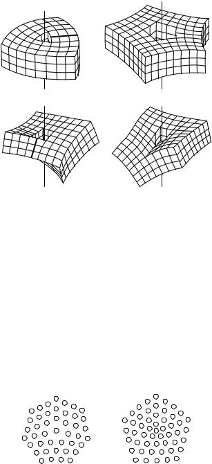
Fig. 9.13. Theoretically possible disclinations in crystals: (a) and (b) wedge disclinations, (c) and (d) screw disclinations
the disclination core were also shown, the reader would see that the coordination number there is one more or one less than elsewhere. Parts (c) and (d) show screw disclinations. In this case the finite angular range in which atoms are removed or inserted is not parallel but perpendicular to the disclination line.
Such defects are of academic interest in crystalline solids. However, a wide variety of disclinations may appear in liquid crystals because of their smaller mechanical rigidity and the presence of crystalline order along one or two directions only. An exhaustive listing and rigorous mathematical discussion of all possible types of disclination requires the apparatus of algebraic topology. Figure 9.14 shows the arrangements of columns around longitudinal wedge disclinations of angles −π/3 and π/3 in the discotic columnar phase. The
Fig. 9.14. Wedge disclinations in a columnar liquid crystal. Columns are shown in a top view

292 9 The Structure of Real Crystals
central column is surrounded by five others in the first and seven others in the second case.
9.2.5 Dislocations in Hexagonal Lattices
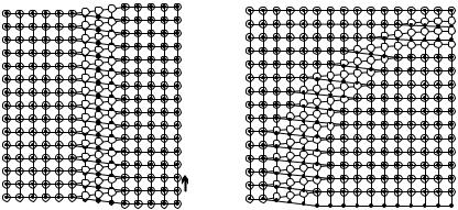
A special situation arises in hexagonal structures – as well as in face-centered cubic ones, where atoms in the (111) plane are arranged hexagonally. Figure 9.15 shows yet another Volterra construction in a two-dimensional hexagonal crystal. The crystal is cut along two lines that are 60◦ apart and have a common end point (in three dimensions: dislocation line), and then all atoms inside the wedge-shaped region are displaced in the direction perpendicular to a1 so that each atom moves exactly one line forward.
Fig. 9.15. Atomic arrangement around the dislocation in a hexagonal structure. The coordination number is seven and five for atoms marked by large and small circles, respectively
As it can be seen, the Burgers circuit can be closed by the vector a1, so this is the Burgers vector of the dislocation. The same atomic arrangement arises when the crystal is cut halfway along the direction of the primitive vector a2 and a new line of atoms is inserted. Since a1 and a2 are at 120◦ to each other, the atoms are arranged in such a way as if in addition to the line of atoms along the a2 direction another one, along a1 + a2 had also been inserted. When one takes a closer look at the region around the dislocation core, the atom at the tip of the wedge is seen to have five nearest neighbors, while the one next to it has seven. This dislocation is thus the same as two nearby disclinations, one at −60◦ and the other at 60◦. As we shall see in the next section, dislocations of a face-centered cubic crystal can also be considered as complex defects.